Automobile training 41 instrument panel
Bạn đang xem bản rút gọn của tài liệu. Xem và tải ngay bản đầy đủ của tài liệu tại đây (5.59 MB, 89 trang )
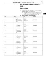
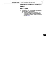
INSTRUMENT PANEL – UPPER INSTRUMENT PANEL (for Sedan)
IP–1
UPPER INSTRUMENT PANEL (for
Sedan)
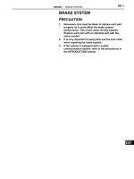
PRECAUTION
1.
PRECAUTION FOR VEHICLES WITH SRS AIRBAG
AND SEAT BELT PRETENSIONER
(a) Some of these operations may affect the SRS
airbag system. Read the precautionary notices
concerning the SRS airbag system before servicing
(See page RS-1).
IP
IP–2
INSTRUMENT PANEL – UPPER INSTRUMENT PANEL (for Sedan)
COMPONENTS
COMBINATION
METER ASSEMBLY
INSTRUMENT CLUSTER
FINISH PANEL
IP
INSTRUMENT PANEL
FINISH PANEL END RH
INSTRUMENT PANEL
FINISH PANEL END LH
INSTRUMENT PANEL FINISH
PANEL LOWER CENTER
E116817E01
INSTRUMENT PANEL – UPPER INSTRUMENT PANEL (for Sedan)
IP–3
w/ Curtain Shield Airbag:
SPECIAL CLIP
SPECIAL CLIP
FRONT PILLAR
GARNISH LH
FRONT PILLAR
GARNISH LH
FRONT PILLAR
GARNISH RH
FRONT PILLAR
GARNISH RH
FRONT DOOR OPENING
TRIM WEATHERSTRIP RH
FRONT DOOR OPENING
TRIM WEATHERSTRIP LH
<B>
<B>
IP
<C>
20 (204, 15)
<C>
UPPER INSTRUMENT
PANEL SUB-ASSEMBLY
GLOVE COMPARTMENT
DOOR ASSEMBLY
N*m (kgf*cm, ft*lbf) : Specified torque
Non-reusable part
B132310E02
IP–4
INSTRUMENT PANEL – UPPER INSTRUMENT PANEL (for Sedan)
FRONT PASSENGER
AIRBAG ASSEMBLY
NO. 2 HEATER TO
REGISTER DUCT
<A>
NO. 1 HEATER TO
REGISTER DUCT
<A>
NO. 1 INSTRUMENT PANEL
REGISTER ASSEMBLY
<A>
<A>
NO. 1 INSTRUMENT PANEL
REGISTER ASSEMBLY
INSTRUMENT
PANEL CUSHION
IP
UPPER INSTRUMENT
PANEL
NO. 1 INSTRUMENT
PANEL CUSHION
NO. 2 INSTRUMENT
PANEL CUSHION
NO. 3 INSTRUMENT
PANEL CUSHION
B132378E01
IP–5
INSTRUMENT PANEL – UPPER INSTRUMENT PANEL (for Sedan)
REMOVAL
HINT:
Use the same procedure for both the RH and LH sides.
1.
BOLTS, SCREWS AND NUTS TABLE
HINT:
All bolts, screws and nuts relevant to installing and
removing the instrument panel are shown, along with
their alphabetic codes, in the table below.
mm(in.) (L=Length)
Code
<A>
Code
Shape
φ=5
(0.20)
L=14
(0.55)
Code
Shape
φ=5
(0.20)
L=14
(0.55)
<B>
<C>
Shape
φ=8
(0.31)
L=15
(0.59)
B118994E01
2.
DISCONNECT CABLE FROM NEGATIVE BATTERY
TERMINAL
(a) Wait for at least 90 seconds after disconnecting the
cable to prevent the airbag from working.
3.
REMOVE INSTRUMENT PANEL FINISH PANEL
LOWER CENTER (See page ME-138)
4.
REMOVE INSTRUMENT PANEL FINISH PANEL END
LH (See page ME-138)
5.
REMOVE INSTRUMENT PANEL FINISH PANEL END
RH (See page ME-138)
6.
REMOVE INSTRUMENT CLUSTER FINISH PANEL
(See page ME-139)
7.
REMOVE COMBINATION METER ASSEMBLY (See
page ME-139)
8.
SEPARATE FRONT DOOR OPENING TRIM
WEATHERSTRIP RH
(a) Separate the front door opening trim weatherstrip.
9.
SEPARATE FRONT DOOR OPENING TRIM
WEATHERSTRIP LH
(a) Separate the front door opening trim weatherstrip.
10. REMOVE FRONT PILLAR GARNISH RH (See page IR18)
11. REMOVE FRONT PILLAR GARNISH LH (See page IR19)
IP
IP–6
INSTRUMENT PANEL – UPPER INSTRUMENT PANEL (for Sedan)
Stopper
12. REMOVE GLOVE COMPARTMENT DOOR
ASSEMBLY
(a) Disengage the claw and separate the 2 glove
compartment door stoppers from the glove
compartment door.
(b) Slightly flex the upper part of the glove compartment
door to release the 2 stoppers and open the glove
compartment door assembly until it becomes
horizontal.
B132319E01
(c) Pull the glove compartment door assembly out
horizontally to disengage the hinge portion and
remove the glove compartment door.
NOTICE:
Pull the glove compartment door out
horizontally, otherwise, installation failure
caused by excessive play around the hinge
portion will result.
Hinge
B132320E01
13. REMOVE UPPER INSTRUMENT PANEL SUBASSEMBLY
(a) Slide the slider and disconnect the passenger
airbag connector.
(b) Disconnect the clamp.
IP
Slider
B132322E01
INSTRUMENT PANEL – UPPER INSTRUMENT PANEL (for Sedan)
IP–7
(c) Remove the 2 <C> bolts and 2 <B> screws.
<B>
<B>
<C>
<C>
B132323E01
IP
IP–8
INSTRUMENT PANEL – UPPER INSTRUMENT PANEL (for Sedan)
(d) Disengage the 7 clips by lifting the rear side of the
instrument panel up.
IP
B132324
(e) While lifting the instrument panel, slide it toward the
rear of the vehicle. Disengage the 5 claws from the
front side of the instrument panel and remove the
instrument panel.
14. REMOVE NO. 2 HEATER TO REGISTER DUCT
(a) Remove the 2 <A> screws and remove the register
duct.
B132325
INSTRUMENT PANEL – UPPER INSTRUMENT PANEL (for Sedan)
IP–9
15. REMOVE NO. 1 HEATER TO REGISTER DUCT
(a) Remove the 2 <A> screws and remove the register
duct.
B132326
16. REMOVE NO. 1 INSTRUMENT PANEL REGISTER
ASSEMBLY
(a) Disengage the 3 claws and remove the register.
HINT:
Use the same procedure for both sides.
17. REMOVE FRONT PASSENGER AIRBAG ASSEMBLY
(See page RS-328)
B132327
18. REMOVE INSTRUMENT PANEL CUSHION
(a) Remove the instrument panel cushion from the
upper instrument panel.
IP
B132331
19. REMOVE NO. 1 INSTRUMENT PANEL CUSHION
(a) Remove the instrument panel cushion from the
upper instrument panel.
B132328
20. REMOVE NO. 2 INSTRUMENT PANEL CUSHION
(a) Remove the instrument panel cushion from the
upper instrument panel.
B132329
IP–10
INSTRUMENT PANEL – UPPER INSTRUMENT PANEL (for Sedan)
21. REMOVE NO. 3 INSTRUMENT PANEL CUSHION
(a) Remove the instrument panel cushion from the
upper instrument panel.
B132330
INSTALLATION
1.
INSTALL NO. 3 INSTRUMENT PANEL CUSHION
(a) Install the instrument panel cushion onto the upper
instrument panel.
2.
INSTALL NO. 2 INSTRUMENT PANEL CUSHION
(a) Install the instrument panel cushion onto the upper
instrument panel.
3.
INSTALL NO. 1 INSTRUMENT PANEL CUSHION
(a) Install the instrument panel cushion onto the upper
instrument panel.
4.
INSTALL INSTRUMENT PANEL CUSHION
(a) Install the instrument panel cushion onto the upper
instrument panel.
5.
INSTALL FRONT PASSENGER AIRBAG ASSEMBLY
(See page RS-329)
B132330
IP
B132329
B132328
B132332
INSTRUMENT PANEL – UPPER INSTRUMENT PANEL (for Sedan)
IP–11
6.
INSTALL NO. 1 INSTRUMENT PANEL REGISTER
ASSEMBLY
(a) Engage the 3 claws and install the register.
HINT:
Use the same procedure for both sides.
7.
INSTALL NO. 1 HEATER TO REGISTER DUCT
(a) Install the register duct with the 2 <A> screws.
8.
INSTALL NO. 2 HEATER TO REGISTER DUCT
(a) Install the register duct with the 2 <A> screws.
B132327
B132326
IP
B132325
9.
Runner Portion
Cut Off
B130309E01
INSTALL UPPER INSTRUMENT PANEL SUBASSEMBLY
(a) Using a nipper, cut off both ends of the runner
portion shown in the illustration (When installing a
new one).
(b) Engage the 5 claws at the front side of the
instrument panel.
IP–12
INSTRUMENT PANEL – UPPER INSTRUMENT PANEL (for Sedan)
(c) Engage the 7 clips at the rear side of the instrument
panel.
IP
B132324
INSTRUMENT PANEL – UPPER INSTRUMENT PANEL (for Sedan)
IP–13
(d) Install the upper instrument panel with the 2 <C>
bolts and the 2 <B> screws.
<B>
<B>
<C>
<C>
B132323E01
Torque: 20 N*m (204 kgf*cm, 15 ft.*lbf) for bolt
<C>
(e) Connect the passenger airbag connector and
clamp.
IP
B132386
10. INSTALL GLOVE COMPARTMENT DOOR ASSEMBLY
(a) Engage the claws of the hinge portions by pushing
the glove compartment door in the horizontal
direction to install the glove compartment door
assembly.
NOTICE:
Engage the claw by pushing it in the horizontal
direction, otherwise, installation failure caused
by excessive play around the hinge portion will
result.
Hinge
B132321E01
IP–14
INSTRUMENT PANEL – UPPER INSTRUMENT PANEL (for Sedan)
Stopper
(b) Slightly flex the upper portion of the glove
compartment door assembly to engage the stopper.
(c) Install the 2 glove compartment door stoppers onto
the glove compartment door.
11. INSTALL FRONT PILLAR GARNISH RH (See page IR29)
12. INSTALL FRONT PILLAR GARNISH LH (See page IR30)
B132319E01
13. INSTALL FRONT DOOR OPENING TRIM
WEATHERSTRIP RH
(a) Install the front door opening trim weatherstrip.
14. INSTALL FRONT DOOR OPENING TRIM
WEATHERSTRIP LH
(a) Install the front door opening trim weatherstrip.
15. INSTALL COMBINATION METER ASSEMBLY (See
page ME-140)
16. INSTALL INSTRUMENT CLUSTER FINISH PANEL
(See page ME-140)
17. INSTALL INSTRUMENT PANEL FINISH PANEL END
RH (See page ME-141)
18. INSTALL INSTRUMENT PANEL FINISH PANEL END
LH (See page ME-141)
19. INSTALL INSTRUMENT PANEL FINISH PANEL
LOWER CENTER (See page ME-142)
IP
20. CONNECT CABLE TO NEGATIVE BATTERY
TERMINAL
Torque: 5.4 N*m (55 kgf*cm, 48 in.*lbf)
21. CHECK SRS WARNING LIGHT
(See page RS-31)
INSTRUMENT PANEL – UPPER INSTRUMENT PANEL (for Hatchback)
IP–15
UPPER INSTRUMENT PANEL (for
Hatchback)
PRECAUTION
1.
PRECAUTION FOR VEHICLE WITH SRS AIRBAG
AND SEAT BELT PRETENSIONER
(a) Some of these operations may affect the SRS
airbag system. Read the precautionary notices
concerning the SRS airbag system before servicing
(See page RS-31).
IP
IP–16
INSTRUMENT PANEL – UPPER INSTRUMENT PANEL (for Hatchback)
COMPONENTS
COMBINATION METER ASSEMBLY
INSTRUMENT CLUSTER FINISH PANEL
IP
INSTRUMENT PANEL
FINISH PANEL END RH
INSTRUMENT PANEL
FINISH PANEL END LH
E107796E02
IP–17
INSTRUMENT PANEL – UPPER INSTRUMENT PANEL (for Hatchback)
w/ Curtain Shield Airbag:
CLIP
CLIP
CLIP
CLIP
FRONT PILLAR GARNISH RH
FRONT PILLAR GARNISH LH
FRONT PILLAR GARNISH RH
FRONT PILLAR
GARNISH LH
FRONT DOOR OPENING
TRIM WEATHERSTRIP RH
FRONT DOOR OPENING TRIM WEATHERSTRIP LH
UPPER INSTRUMENT
PANEL SUB-ASSEMBLY
<B>
IP
<B>
<B>
<B>
<C>
20 (204, 15)
<C>
NO. 1 SWITCH HOLE BASE
GLOVE COMPARTMENT DOOR ASSEMBLY
N*m (kgf*cm, ft.*lbf) : Specified torque
Non-reusable part
B108209E01
IP–18
INSTRUMENT PANEL – UPPER INSTRUMENT PANEL (for Hatchback)
NO. 2 HEATER TO REGISTER DUCT
NO. 1 HEATER TO
REGISTER DUCT
<A>
NO. 1 INSTRUMENT
PANEL REGISTER
ASSEMBLY
<A>
<A>
<A>
NO. 1 INSTRUMENT PANEL
REGISTER ASSEMBLY
INSTRUMENT PANEL CUSHION
FRONT PASSENGER
AIRBAG ASSEMBLY
UPPER
INSTRUMENT
PANEL
IP
NO. 3 INSTRUMENT
PANEL CUSHION
NO. 2 INSTRUMENT PANEL CUSHION
NO. 1 INSTRUMENT
PANEL CUSHION
INSTRUMENT PANEL CUP
HOLDER SPRING
NO. 1 INSTRUMENT PANEL
BOX DOOR SUB-ASSEMBLY
<A>
<A>
<A>
<A>
INSTRUMENT PANEL
CUP HOLDER SPRING
NO. 2 INSTRUMENT
PANEL CUP HOLDER
NO. 2 INSTRUMENT PANEL
BOX DOOR SUB-ASSEMBLY
NO. 1 INSTRUMENT
PANEL CUP HOLDER
B105349E01
IP–19
INSTRUMENT PANEL – UPPER INSTRUMENT PANEL (for Hatchback)
REMOVAL
HINT:
Use the same procedure for both the RH and LH sides.
1.
BOLTS, SCREWS AND NUTS TABLE
HINT:
All bolts, screws and nuts relevant to installing and
removing the instrument panel are shown, along with
their alphabetic codes, in the table below.
mm(in.) (L=Length)
Code
<A>
Code
Shape
φ=5
(0.20)
L=14
(0.55)
Code
Shape
φ=5
(0.20)
L=14
(0.55)
<B>
Shape
<C>
φ=8
(0.31)
L=15
(0.59)
B118994E01
2.
DISCONNECT CABLE FROM NEGATIVE BATTERY
TERMINAL
(a) Wait for at least 90 seconds after disconnecting the
cable to prevent the airbag from working.
3.
REMOVE INSTRUMENT PANEL FINISH PANEL END
LH (See page ME-145)
4.
REMOVE INSTRUMENT PANEL FINISH PANEL END
RH (See page ME-145)
5.
REMOVE INSTRUMENT CLUSTER FINISH PANEL
(See page ME-145)
6.
REMOVE COMBINATION METER ASSEMBLY (See
page ME-146)
7.
REMOVE FRONT DOOR OPENING TRIM
WEATHERSTRIP RH (See page IR-50)
8.
REMOVE FRONT DOOR OPENING TRIM
WEATHERSTRIP LH (See page IR-50)
9.
REMOVE FRONT PILLAR GARNISH RH (See page IR58)
10. REMOVE FRONT PILLAR GARNISH LH (See page IR59)
IP
IP–20
INSTRUMENT PANEL – UPPER INSTRUMENT PANEL (for Hatchback)
11. REMOVE NO. 1 SWITCH HOLE BASE
(a) Disengage the 2 clips and 2 claws and remove the
switch hole base.
B105353
12. REMOVE GLOVE COMPARTMENT DOOR
ASSEMBLY
(a) Slightly deform the upper part of the glove
compartment door assembly to release the 2
stoppers and open the glove compartment door
assembly until it becomes horizontal.
B108202
(b) Pull the glove compartment door assembly out
horizontally to disengage the hinge portion and
remove the glove compartment door assembly.
NOTICE:
Pull the glove compartment door out
horizontally, otherwise, installation failure
caused by excessive play around the hinge
portion will result.
IP
B105351
IP–21
INSTRUMENT PANEL – UPPER INSTRUMENT PANEL (for Hatchback)
13. REMOVE UPPER INSTRUMENT PANEL SUBASSEMBLY
(a) Slide the slider and disconnect the passenger
airbag connector.
(b) Disconnect the clamp.
(c) Remove the 2 <C> bolts and 4 <B> screws.
Slider
B108181E02
<B>
<B>
<B>
<B>
IP
<C>
<C>
B105354E01
(d) Disconnect the connectors.
(e) Disengage the claw and 3 clips while lifting the rear
instrument panel up.
IP–22
INSTRUMENT PANEL – UPPER INSTRUMENT PANEL (for Hatchback)
(f)
While lifting the instrument panel, slide it toward the
rear of the vehicle. Disengage the 5 claws of the
front side of the instrument panel and remove the
instrument panel.
IP
B105355E01
INSTRUMENT PANEL – UPPER INSTRUMENT PANEL (for Hatchback)
IP–23
14. REMOVE NO. 1 INSTRUMENT PANEL BOX DOOR
SUB-ASSEMBLY
(a) Remove the 2 <A> screws.
(b) Pull the instrument panel box door toward the rear
of the vehicle, disengage the 2 claws and 2 clips
and remove the instrument panel box door.
B105356
15. REMOVE NO. 2 INSTRUMENT PANEL BOX DOOR
SUB-ASSEMBLY
(a) Remove the 2 <A> screws.
(b) Pull the instrument panel box door toward the rear
of the vehicle, disengage the 2 claws and 2 clips
and remove the instrument panel box door.
IP
B105358
16. REMOVE INSTRUMENT PANEL CUP HOLDER
SPRING
(a) Remove screw <A> and remove the cup holder
spring.
B105360
17. REMOVE NO. 1 INSTRUMENT PANEL CUP HOLDER
(a) Slightly deform portion A of the cup holder by
pressing it and release the stopper.
A
A
B108174E01
IP–24
INSTRUMENT PANEL – UPPER INSTRUMENT PANEL (for Hatchback)
(b) Using a screwdriver with its tip wrapped in
protective tape, prize the hinge portion of the cup
holder from side to side while being careful not to
apply excessive load to the axis of the instrument
panel upper, and remove the cup holder.
18. REMOVE NO. 2 INSTRUMENT PANEL CUP HOLDER
HINT:
Use the same procedure as for the RH side.
Protective
Tape
B108173E01
19. REMOVE NO. 2 HEATER TO REGISTER DUCT
(a) Remove the 2 <A> screws and remove the register
duct.
IP
B108177
20. REMOVE NO. 1 HEATER TO REGISTER DUCT
(a) Remove the 2 <A> screws and remove the register
duct.
B108176
INSTRUMENT PANEL – UPPER INSTRUMENT PANEL (for Hatchback)
IP–25
21. REMOVE NO. 1 INSTRUMENT PANEL REGISTER
ASSEMBLY
(a) Disengage the 3 claws and remove the register.
HINT:
Use the same procedure as for the opposite side.
22. REMOVE FRONT PASSENGER AIRBAG ASSEMBLY
(See page RS-340)
B108178
23. REMOVE INSTRUMENT PANEL CUSHION
(a) Remove the instrument panel cushion from the
instrument panel upper.
B108179
24. REMOVE NO. 1 INSTRUMENT PANEL CUSHION
(a) Remove the instrument panel cushion from the
instrument panel upper.
B108203
25. REMOVE NO. 2 INSTRUMENT PANEL CUSHION
(a) Remove the instrument panel cushion from the
instrument panel upper.
B108204
IP