Automobile Training 46 CAN communication
Bạn đang xem bản rút gọn của tài liệu. Xem và tải ngay bản đầy đủ của tài liệu tại đây (4.18 MB, 106 trang )
CAN COMMUNICATION – CAN COMMUNICATION SYSTEM
CA–1
CAN COMMUNICATION SYSTEM
PRECAUTION
1.
2.
3.
4.
F045104
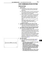
PRECAUTION
(a) Turn the ignition switch off before measuring the
resistances of the CAN main wire and the CAN
branch wire.
(b) After the ignition switch is turned off, check that the
key reminder warning system and light reminder
warning system are not in operation.
(c) Before measuring the resistance, leave the vehicle
as is for at least 1 minute and do not operate the
ignition switch, any other switches or the doors. If
doors need to be opened in order to check
connectors, open the doors and leave them open.
HINT:
Operating the ignition switch, any switches or any
doors triggers related ECU and sensor
communication with the CAN, which causes
resistance variation.
STEERING SYSTEM HANDLING PRECAUTIONS
(a) Care must be taken when replacing parts. Incorrect
replacement could affect the performance of the
steering system and result in hazards when driving.
SRS AIRBAG SYSTEM HANDLING PRECAUTIONS
(a) This vehicle is equipped with an SRS
(Supplemental Restraint System) such as the driver
airbag and front passenger airbag. Failure to carry
out service operations in the correct sequence could
cause unexpected SRS deployment during
servicing and may lead to a serious accident. Before
servicing (including removal or installation of parts,
inspection or replacement), be sure to read the
precautionary notice for the Supplemental Restraint
System (See page RS-1).
BUS LINE REPAIR
(a) After repairing the bus line with solder, wrap the
repaired part with vinyl tape (See page IN-34).
NOTICE:
• The CANL bus line and CANH bus line must
always be installed together.
• When installing, twist them together.
• CAN bus lines are likely to be influenced by
noise if the bus lines are not twisted together.
• The difference in length between the CANL
bus line and CANH bus line should be less
than 100 mm (3.937 in.).
• Leave approximately 80 mm (3.150 in.) loose
in the twisted wires around the connectors.
CA
CA–2
CAN COMMUNICATION – CAN COMMUNICATION SYSTEM
(b) Do not use bypass wiring between the connectors.
NOTICE:
The feature of the twisted wire harness will be
lost if bypass wiring is used.
Bypass Wire
F045105E01
5.
CONNECTOR HANDLING
(a) When inserting tester probes into a connector, insert
them from the rear of the connector.
Tester Probe
F045106E04
(b) Use a repair wire to check the connector if it is
impossible to check resistance from the rear of the
connector.
Repair Wire
F045107E08
CA
CAN COMMUNICATION – CAN COMMUNICATION SYSTEM
CA–3
PARTS LOCATION
HATCHBACK:
ECM
BRAKE ACTUATOR
(SKID CONTROL ECU)*
*: W/ ABS
C126027E02
CA
CA–4
CAN COMMUNICATION – CAN COMMUNICATION SYSTEM
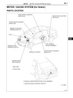
SEDAN:
ECM
*: W/ ABS
BRAKE ACTUATOR (SKID CONTROL ECU)*
C139123E02
CA
CAN COMMUNICATION – CAN COMMUNICATION SYSTEM
CA–5
HATCHBACK:
MAIN BODY ECU
(INSTRUMENT PANEL J/B)
POWER STEERING ECU
COMBINATION METER ECU
P-CAN J/C
(JUNCTION CONNECTOR)
DLC3
AIR CONDITIONING
AMPLIFIER*
CA
D-CAN J/C
(JUNCTION CONNECTOR)
CENTER AIRBAG SENSOR ASSEMBLY
*: W/ AIR CONDITIONING OR PTC HEATER
C118152E03
CA–6
CAN COMMUNICATION – CAN COMMUNICATION SYSTEM
SEDAN:
POWER STEERING ECU
MAIN BODY ECU
(INSTRUMENT PANEL J/B)
COMBINATION METER ECU
AIR CONDITIONING
AMPLIFIER*
DLC3
P-CAN J/C
CA
D-CAN J/C
(JUNCTION CONNECTOR)
(JUNCTION CONNECTOR)
CENTER AIRBAG SENSOR ASSEMBLY
*: W/ AIR CONDITIONING OR PTC HEATER
C139125E02
CA–7
CAN COMMUNICATION – CAN COMMUNICATION SYSTEM
SYSTEM DIAGRAM
*1: w/ ABS
ECM
*2: w/ Air Conditioning or PTC Heater
D-CAN J/C
Air Conditioning
Amplifier*2
(Junction Connector)
DLC3
Center Airbag Sensor
Assembly
Brake Actuator (Skid
Control ECU)*1
Combination Meter
ECU
Main Body ECU
P-CAN J/C
(Junction Connector)
Power Steering ECU
CA
: CAN Main Wire (CAN-L)
: CAN Branch Wire (CAN-L)
: CAN Main Wire (CAN-H)
: CAN Branch Wire (CAN-H)
C118153E12
HINT:
The power steering ECU and center airbag sensor assembly
use the CAN communication system to perform DTC
communication instead of the conventional communication
line (SIL).
CA–8
CAN COMMUNICATION – CAN COMMUNICATION SYSTEM
SYSTEM DESCRIPTION
1.
2.
3.
CA
4.
BRIEF DESCRIPTION
(a) The CAN (Control Area Network) is a serial data
communication system for real time application. It is
a vehicle multiplex communication system which
has a high communication speed (500 kbps) and
the ability to detect malfunctions.
(b) By pairing the CANH and CANL bus lines, the CAN
performs communication based on differential
voltages.
(c) Many ECUs (sensors) installed on the vehicle
operate by sharing information and communicating
with each other.
(d) The CAN has two 120 Ω resistors which are
necessary to communicate with the main wire.
DEFINITION OF TERMS
(a) Main wire
(1) The main wire is a wire harness between the two
terminus circuits on the bus (communication
line). This is the main bus in the CAN
communication system.
(b) Branch wire
(1) The branch wire is a wire harness which
diverges from the main wire to an ECU or
sensor.
(c) Terminus circuit
(1) The terminus circuit is a circuit which converts
the communication current of the CAN
communication into the bus voltage. It consists
of a resistor and condenser. Two terminus
circuits are necessary on a bus.
(d) CAN J/C
(1) The CAN J/C is a junction designed for CAN
communication.
ECUs OR SENSORS WHICH COMMUNICATE VIA
CAN COMMUNICATION SYSTEM
(a) Brake actuator (Skid control ECU)*1
(b) Power steering ECU
(c) ECM
(d) Center airbag sensor assembly
(e) Air conditioning amplifier*2
(f) Combination meter ECU
(g) Main body ECU
HINT:
*1: w/ ABS
*2: w/ Air conditioning or PTC heater
DIAGNOSTIC CODES FOR CAN COMMUNICATION
SYSTEM
(a) DTCs for the CAN communication system are as
follows: U0073, U0100, U0105, U0121, U0129 and
B1499.
CAN COMMUNICATION – CAN COMMUNICATION SYSTEM
5.
CA–9
NOTES REGARDING TROUBLESHOOTING
(a) Trouble in the CAN bus (communication line) can be
checked through the DLC3 (except when there is a
wire break other than in the branch wire of the
DLC3).
NOTICE:
Do not connect the tester directly to the DLC3
connector. Be sure to use a service wire.
(b) DTCs regarding the CAN communication system
can be checked using the intelligent tester via the
CAN VIM.
(c) The CAN communication system cannot detect
trouble in the branch wire of the DLC3 even though
the DLC3 is also connected to the CAN
communication system.
CA
CA–10
CAN COMMUNICATION – CAN COMMUNICATION SYSTEM
HOW TO PROCEED WITH
TROUBLESHOOTING
NOTICE:
• DTCs for the CAN communication system are as
follows: U0073, U0100, U0105, U0121, U0129 and
B1499.
• Refer to the troubleshooting section for each system if
DTCs regarding the CAN communication system are
not output.
• Turn the ignition switch off before measuring the
resistances of the CAN main wire and the CAN branch
wire.
• After the ignition switch is turned off, check that the
key reminder warning system and light reminder
warning system are not in operation.
• Before measuring the resistance, leave the vehicle as
is for at least 1 minute and do not operate the ignition
switch, any other switches or the doors. If doors need
to be opened in order to check connectors, open the
doors and leave them open.
HINT:
Operating the ignition switch, any switches or any
doors triggers related ECU and sensor
communication with the CAN, which causes
resistance variation.
1
CHECK CAN BUS LINE
(a) Check the CAN bus line (See page CA-42).
NEXT
2
CHECK INSTALLED SYSTEMS (ECUs AND SENSORS) THAT ADOPT CAN
COMMUNICATION
NEXT
CA
3
CHECK AND CLEAR DTCs
NEXT
4
CHECK CAN COMMUNICATION USING INTELLIGENT TESTER VIA CAN VIM
(a) Select "BUS CHECK" (See page CA-22).
Result
All ECUs and sensors connected to CAN communication system
displayed on screen.
A
One ECU or sensor connected to CAN communication system not
displayed on screen.
B
CAN COMMUNICATION – CAN COMMUNICATION SYSTEM
2 or more ECUs and sensors connected to CAN communication
system not displayed on screen.
CA–11
C
NOTICE:
• The systems (ECUs and sensors) that adopt CAN
communication vary depending on the vehicle
and option settings. Check which systems (ECUs
and sensors) are installed on the vehicle (See
page CA-22).
• Non-installed ECUs or sensors are not displayed.
Do not mistake them for being in communication
stop mode.
• If 2 or more ECUs or sensors are not displayed on
the intelligent tester via the CAN VIM, perform
troubleshooting for open in one side of CAN bus
line for each undisplayed ECU or sensor.
B
GO TO COMMUNICATION STOP MODE
TABLE
C
GO TO OPEN IN ONE SIDE OF CAN BRANCH
WIRE
A
5
DTC COMBINATION TABLE
(a) Confirm trouble according to the combination of output
DTCs regarding the CAN communication system.
HINT:
Previous CAN communication system DTCs may be the
cause if CAN communication system DTCs are output
and all ECUs and sensors connected to the CAN
communication system are displayed on the intelligent
tester's "BUS CHECK" screen via the CAN VIM.
NEXT
6
INSPECT CIRCUIT
CA
NEXT
7
IDENTIFY PROBLEM
NEXT
8
NEXT
REPAIR OR REPLACE
CA–12
9
NEXT
END
CA
CAN COMMUNICATION – CAN COMMUNICATION SYSTEM
PERFORM CONFIRMATION TEST
CAN COMMUNICATION – CAN COMMUNICATION SYSTEM
CA–13
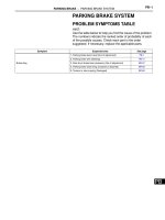
PROBLEM SYMPTOMS TABLE
RESULT LIST OF CHECK CAN BUS LINE
Symptom
Open in CAN Main Wire
Suspected area
See page
Check CAN Main Wire for Disconnection
CA-46
Short in CAN Bus Line
Check CAN Bus Lines for Short Circuit
CA-52
Short to +B in CAN Bus Line
Check CAN Bus Line for Short to +B
CA-67
Short to GND in CAN Bus Line
Check CAN Bus Line for Short to GND
CA-82
Open in One Side of CAN Branch Wire
Check for Open in One Side of Branch Wire
CA-97
COMMUNICATION STOP MODE TABLE
Symptom
Suspected area
See page
"EPS" not displayed on intelligent tester via CAN VIM.
Power Steering ECU Communication Stop Mode
CA-31
"ENGINE" not displayed on intelligent tester via CAN
VIM.
ECM Communication Stop Mode
CA-33
"SRS AIRBAG" not displayed on intelligent tester via
CAN VIM.
Center Airbag Sensor Communication Stop Mode
CA-40
"A/C*1" not displayed on intelligent tester via CAN
VIM.
Air Conditioning Amplifier Communication Stop Mode
CA-29
"MAIN BODY" not displayed on intelligent tester via
CAN VIM.
Main Body ECU Communication Stop Mode
CA-35
"ABS/VSC/TRAC*2" not displayed on intelligent tester
via CAN VIM.
Brake Actuator (Skid Control ECU) Communication Stop Mode
CA-27
"METER" not displayed on intelligent tester via CAN
VIM.
Combination Meter ECU Communication Stop Mode
CA-38
*1: w/ Air conditioning or PTC heater
*2: w/ ABS
CA
CA–14
CAN COMMUNICATION – CAN COMMUNICATION SYSTEM
TERMINALS OF ECU
NOTICE:
• Turn the ignition switch off before measuring the
resistances of the CAN main wire and the CAN branch
wire.
• After the ignition switch is turned off, check that the
key reminder warning system and light reminder
warning system are not in operation.
• Before measuring the resistance, leave the vehicle as
is for at least 1 minute and do not operate the ignition
switch, any other switches or the doors. If doors need
to be opened in order to check connectors, open the
doors and leave them open.
HINT:
Operating the ignition switch, any switches or any
doors triggers related ECU and sensor
communication with the CAN, which causes
resistance variation.
1.
Wire Harness Side:
D-CAN J/C Connector
D41
Front View
JUNCTION CONNECTOR
(a) D-CAN J/C
D-CAN J/C connectors
Terminal
Color
Brake actuator (Skid
control ECU*1 (CAN-H))
D41-1 (ABS)
G
Brake actuator (Skid
control ECU*1 (CAN-L))
D41-12 (ABS)
W
DLC3 (CAN-H)
D41-3 (OBD)
V
DLC3 (CAN-L)
D41-14 (OBD)
W
ECM (CAN-H)
D41-4 (EFI)
L
ECM (CAN-L)
D41-15 (EFI)
W
Air Conditioning
Amplifier*2 (CAN-H)
D41-6 (A/C)
V
Air Conditioning
Amplifier*2 (CAN-L)
D41-17 (A/C)
W
Center Airbag Sensor
Assembly (CAN-H)
D41-8 (A/B)
B
Center Airbag Sensor
Assembly (CAN-L)
D41-19 (A/B)
W
CAN main wire (between
D-CAN and P-CAN J/C)
D41-11 (TORH)
Y
CAN main wire (between
D-CAN and P-CAN J/C)
D41-22 (TORH)
W
C118162E06
CA
HINT:
*1: w/ ABS
*2: w/ Air conditioning or PTC heater
CA–15
CAN COMMUNICATION – CAN COMMUNICATION SYSTEM
2.
Wire Harness Side:
P-CAN J/C Connector
D42
Front View
C118162E07
JUNCTION CONNECTOR
(a) P-CAN J/C
P-CAN J/C connectors
Terminal
Color
Power Steering ECU
(CAN-H)
D42-4 (EPS)
SB
Power Steering ECU
(CAN-L)
D42-15 (EPS)
W
Main Body ECU (CAN-H)
D42-5 (JB)
R
Main Body ECU (CAN-L)
D42-16 (JB)
W
Combination Meter ECU
(CAN-H)
D42-7 (MET)
G
Combination Meter ECU
(CAN-L)
D42-18 (MET)
W
CAN main wire (between
P-CAN and D-CAN J/C)
D42-11 (TOLH)
Y
CAN main wire (between
P-CAN and D-CAN J/C)
D42-22 (TOLH)
W
CA
CA–16
CAN COMMUNICATION – CAN COMMUNICATION SYSTEM
(b) Wiring diagram for identifying CAN J/C connectors
Center Airbag Sensor
Assembly
CANH CANL
A/B
A/B
Brake Actuator (Skid
Control ECU)*1
Air Conditioning
Amplifier*2
TX+
TX-
A/C
A/C
CANH CANL
ABS
ABS
D-CAN J/C (Junction Connector)
EFI
EFI
CANH CANL
OBD
OBD
TORH TORH
CANH CANL
DLC3
ECM
TOLH
TOLH
EPS
EPS
P-CAN J/C (Junction Connector)
JB
CANH
JB
CANL
Main Body ECU
CA
MET
MET
CANH CANL
CANH CANL
Combination Meter ECU
Power Steering ECU
*1: w/ ABS
*2: w/ Air Conditioning or PTC Heater
C118154E01
CA–17
CAN COMMUNICATION – CAN COMMUNICATION SYSTEM
DLC3:
3.
D15
CG
CANL
CANH
DLC3
(a) Turn the ignition switch OFF.
(b) Measure the resistance.
BAT
G026206E60
Standard resistance
Terminals
Wiring Color
Condition
Specified Condition
D15-6 (CANH) - D15-14 (CANL)
V-W
Ignition Switch OFF
54 to 69 Ω
D15-6 (CANH) - D15-4 (CG)
V - W-B
Ignition Switch OFF
200 Ω or higher
D15-14 (CANL) - D15-4 (CG)
W - W-B
Ignition Switch OFF
200 Ω or higher
D15-6 (CANH) - D15-16 (BAT)
V - SB
Ignition Switch OFF
6 kΩ or higher
D15-14 (CANL) - D15-16 (BAT)
W - SB
Ignition Switch OFF
6 kΩ or higher
4.
(a) Turn the ignition switch OFF.
(b) Disconnect the A15 brake actuator (skid control
ECU) connector.
(c) Measure the resistance.
Wire Harness Side:
Brake Actuator (Skid Control ECU)
Connector
CANL
BRAKE ACTUATOR (SKID CONTROL ECU)
HINT:
For vehicle with ABS only.
CANH
+BS
A15
GND1
Front View
C118165E10
Standard resistance
Terminals
Wiring Color
Condition
Specified Condition
A15-6 (CANH) - A15-5 (CANL)
G-W
Ignition Switch OFF
54 to 69 Ω
A15-6 (CANH) - A15-2 (GND1)
G - W-B
Ignition Switch OFF
200 Ω or higher
A15-5 (CANL) - A15-2 (GND1)
W - W-B
Ignition Switch OFF
200 Ω or higher
A15-6 (CANH) - A15-1 (+BS)
G-W
Ignition Switch OFF
6 kΩ or higher
A15-5 (CANL) - A15-1 (+BS)
W-W
Ignition Switch OFF
6 kΩ or higher
CA
CA–18
CAN COMMUNICATION – CAN COMMUNICATION SYSTEM
5.
Wire Harness Side:
ECM Connector
ECM
(a) Turn the ignition switch OFF.
(b) Disconnect the A21 and C20 ECM connectors.
(c) Measure the resistance.
A21
CANH
BATT
C20
Front View
Front View
CANL
E1
G100287E02
Standard resistance
CA
Terminals
Wiring Color
Condition
Specified Condition
A21-41 (CANH) - A21-49 (CANL)
L-W
Ignition switch OFF
108 to 132 Ω
A21-41 (CANH) - C20-104 (E1)
L-W
Ignition switch OFF
200 Ω or higher
A21-49 (CANL) - C20-104 (E1)
W-W
Ignition switch OFF
200 Ω or higher
A21-41 (CANH) - A21-20 (BATT)
L-Y
Ignition switch OFF
6 kΩ or higher
A21-49 (CANL) - A21-20 (BATT)
W-Y
Ignition switch OFF
6 kΩ or higher
CA–19
CAN COMMUNICATION – CAN COMMUNICATION SYSTEM
6.
Wire Harness Side:
Center Airbag Sensor Assembly Connector
D16
CENTER AIRBAG SENSOR ASSEMBLY
(a) Turn the ignition switch OFF.
(b) Disconnect the D16 center airbag sensor assembly
connector.
(c) Measure the resistance.
CANH
E1
CANL
DLC3:
D15
BAT
C131070E05
Standard resistance
Terminals
Wiring Color
Condition
Specified Condition
D16-13 (CANH) - D16-22 (CANL)
B-W
Ignition switch OFF
54 to 69 Ω
D16-13 (CANH) - D16-25 (E1)
B - W-B
Ignition switch OFF
200 Ω or higher
D16-22 (CANL) - D16-25 (E1)
W - W-B
Ignition switch OFF
200 Ω or higher
D16-13 (CANH) - D15-16 (BAT)
B - SB
Ignition switch OFF
6 kΩ or higher
D16-22 (CANL) - D15-16 (BAT)
W - SB
ignition switch OFF
6 kΩ or higher
7.
AIR CONDITIONING AMPLIFIER
HINT:
For vehicle with air conditioning or PTC heater only.
CA
CA–20
CAN COMMUNICATION – CAN COMMUNICATION SYSTEM
(a) Turn the ignition switch OFF.
(b) Disconnect the E8 air conditioning amplifier
connector.
(c) Measure the resistance.
Wire Harness Side:
Air Conditioning Amplifier Connector
E8
TX-
TX+
GND
DLC3:
D15
BAT
C118854E03
Standard resistance
CA
Terminals
Wiring Color
Condition
Specified Condition
E8-2 (TX+) - E8-3 (TX-)
V-W
Ignition switch OFF
54 to 69 Ω
E8-2 (TX+) - E8-12 (GND)
V - W-B
Ignition switch OFF
200 Ω or higher
E8-3 (TX-) - E8-12 (GND)
W - W-B
Ignition switch OFF
200 Ω or higher
E8-2 (TX+) - D15-16 (BAT)
V - SB
Ignition switch OFF
6 kΩ or higher
E8-3 (TX-) - D15-16 (BAT)
W - SB
Ignition switch OFF
6 kΩ or higher
CA–21
CAN COMMUNICATION – CAN COMMUNICATION SYSTEM
8.
MAIN BODY ECU
Main Body ECU (Rear View):
4H
4D
4C
4A
4E
4D
4K
4A
4B
4C
4J
4H
4E
4J
4K
4B
4L
4L
4G
4F
4F
4G
E114510E13
CA
CA–22
CAN COMMUNICATION – CAN COMMUNICATION SYSTEM
Main Body ECU (Front View):
4S
D33
D33
4M
4M
4S
4P
4Q
4Q
4P
B108641E12
(a) Turn the ignition switch OFF.
(b) Disconnect the 4B and 4E main body ECU
connectors.
(c) Measure the resistance.
CA
Standard resistance
Terminals
Wiring Color
Condition
Specified Condition
D33-23 (CANH) - D33-22 (CANL)
R-W
Ignition switch OFF
54 to 69 Ω
D33-23 (CANH) - 4E-17 (GND1)
R - W-B
Ignition switch OFF
200 Ω or higher
D33-22 (CANL) - 4E-17 (GND1)
W - W-B
Ignition switch OFF
200 Ω or higher
D33-23 (CANH) - 4B-30 (BECU)
R-L
Ignition switch OFF
6 kΩ or higher
D33-22 (CANL) - 4B-30 (BECU)
W-L
Ignition switch OFF
6 kΩ or higher
CA–23
CAN COMMUNICATION – CAN COMMUNICATION SYSTEM
9.
Wire Harness Side:
Combination Meter ECU Connector
D1
COMBINATION METER ECU
(a) Turn the ignition switch OFF.
(b) Disconnect the D1 combination meter ECU
connector.
(c) Measure the resistance.
CANL
ECUB
ET
Front View
CANH
C139156E05
Standard resistance
Terminals
Wiring Color
Condition
Specified Condition
D1-20 (CANH) - D1-21 (CANL)
G-W
Ignition switch OFF
54 to 69 Ω
D1-20 (CANH) - D1-24 (ET)
G - BR
Ignition switch OFF
200 Ω or higher
D1-21 (CANL) - D1-24 (ET)
W - BR
Ignition switch OFF
200 Ω or higher
D1-20 (CANH) - D1-2 (ECUB)
G-L
Ignition switch OFF
6 kΩ or higher
D1-21 (CANL) - D1-2 (ECUB)
W-L
Ignition switch OFF
6 kΩ or higher
10. POWER STEERING ECU
(a) Turn the ignition switch OFF.
(b) Disconnect the A19 and D31 power steering ECU
connectors.
(c) Measure the resistance.
Wire Harness Side:
Power Steering ECU Connector
A19
D31
PIG
CANH
CANL
PGND
CA
C118163E03
Standard resistance
Terminals
Wiring Color
Condition
Specified Condition
D31-1 (CANH) - D31-7 (CANL)
SB - W
Ignition switch OFF
108 to 132 Ω
D31-1 (CANH) - A19-2 (PGND)
SB - W-B
Ignition switch OFF
200 Ω or higher
D31-7 (CANL) - A19-2 (PGND)
W - W-B
Ignition switch OFF
200 Ω or higher
D31-1 (CANH) - A19-1 (PIG)
SB - W
Ignition switch OFF
6 kΩ or higher
D31-7 (CANL) - A19-1 (PIG)
W-W
Ignition switch OFF
6 kΩ or higher
CA–24
CAN COMMUNICATION – CAN COMMUNICATION SYSTEM
DIAGNOSIS SYSTEM
1.
BUS CHECK
(a) Select "BUS CHECK" from the "OBD/MOBD
MENU" screen.
HINT:
The ECUs and sensors that are properly connected
to the CAN communication system can be displayed
using the intelligent tester via the CAN VIM.
G032145
(b) Press "ENTER" on the intelligent tester via the CAN
VIM.
G030152
G032144
2.
CA
(c) The screen displays the ECUs and sensors that are
properly connected to the CAN communication
system.
HINT:
• If any properly connected ECUs or sensors are
not displayed, there is a communication stop in
the system (See page CA-11).
• Display the "BUS CHECK" screen for
approximately 1 minute and check for ECUs and
sensors that a not indicated on the screen.
CHECK INSTALLED SYSTEMS (ECUs AND
SENSORS) THAT ADOPT CAN COMMUNICATION
(a) Systems (ECUs and sensors) that adopt CAN
communication vary depending on the vehicle's
optional settings. Check which systems (ECUs,
sensors) are installed on the vehicle.
ECU/Sensor name
Check method
Brake actuator (Skid control ECU)
with ABS
Power steering ECU
Installed on all vehicles
ECM
Installed on all vehicles
Center airbag sensor assembly
Installed on all vehicles
Air conditioning amplifier
with air conditioning or PTC heater
Combination meter ECU
Installed on all vehicles
Main body ECU
Installed on all vehicles
3.
DTC TABLE BY ECU
HINT:
• In the CAN communication system, CAN
communication system DTCs output by the ECU can
be displayed by using the intelligent tester.
CAN COMMUNICATION – CAN COMMUNICATION SYSTEM
CA–25
• If CAN communication system DTCs are output,
trouble cannot be determined solely from the DTCs.
Perform troubleshooting according to "HOW TO
PROCEED WITH TROUBLESHOOTING" (See page
CA-9).
(a) BRAKE ACTUATOR (SKID CONTROL ECU)
HINT:
DTC communication uses the CAN communication
system.
DTC No.
U0073/94
Detection Item
Control Module Communication Bus OFF
(b) POWER STEERING ECU
HINT:
DTC communication uses the SIL Line.
DTC No.
Detection Item
U0073
Control Module Communication Bus OFF
U0105
Lost Communication with ECM
U0121*
Lost Communication with Anti-lock Brake System (ABS) Control
Module
*: For vehicle with ABS only.
(c) COMBINATION METER ASSEMBLY
HINT:
DTC communication uses the CAN communication
system.
DTC No.
Detection Item
U0100
Lost Communication with ECM/PCM "A"
U0129*
Lost Communication with Brake System Control Module
*: For vehicle with ABS only.
(d) AIR CONDITIONING AMPLIFIER
HINT:
DTC communication uses the CAN communication
system.
DTC No.
B1499/99
Detection Item
Multiplex Communication Circuit
(e) MAIN BODY ECU
HINT:
• The main body ECU is connected to the CAN
communication system but CAN communication
DTCs are not output.
• If "MAIN BODY" is not displayed on the "BUS
CHECK" screen on the intelligent tester, proceed
to "Main Body ECU Communication Stop Mode."
(See page CA-35)
(f) CENTER AIRBAG SENSOR ASSEMBLY
HINT:
• The center airbag sensor assembly is connected
to the CAN communication system but CAN
communication DTCs are not output.
CA