Engineering Tribology 2E Episode 8 ppt
Bạn đang xem bản rút gọn của tài liệu. Xem và tải ngay bản đầy đủ của tài liệu tại đây (399.62 KB, 45 trang )
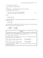
ELASTOHYDRODYNAMIC LUBRICATION 291
It can be noted that for the spheres:
R
ax
= R
ay
= R
A
and R
bx
= R
by
= R
B
where:
R
A
and R
B
are the radii of the spheres ‘A’ and ‘B’ respectively.
Substituting into equation (7.2) gives:
=
1
R'
+
1
R
x
=
1
R
y
+
1
R
A
+
1
R
B
+
1
R
A
1
R
B
= 2
()
+
1
R
A
1
R
B
(7.7)
where:
=
1
R
x
=
1
R
y
+
1
R
A
1
R
B
It should be noted that in some publications the reduced radius for the contact between two
spheres is defined as:
1
R'
=+
1
R
A
1
R
B
and consequently the formulae for the contact area dimension ‘a’ and the maximum
deflection ‘δ’ are presented in the slightly altered form:
a =
3WR'
2E'
()
1/3
δ= 1.31
W
2
E'
2
R'
()
1/3
,
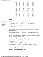
EXAMPLE
Find the contact parameters for two steel balls. The normal force is W = 5 [N], the radii
of the balls are R
A
= 10 × 10
-3
[m] and R
B
= 15 × 10
-3
[m]. The Young's modulus for both
balls is E = 2.1 × 10
11
[Pa] and the Poisson's ratio of steel is υ = 0.3.
· Reduced Radius of Curvature
Since R
ax
= R
ay
= R
A
= 10 × 10
-3
[m] and R
bx
= R
by
= R
B
= 15 × 10
-3
[m] the reduced radii of
curvature in the ‘x’ and ‘y’ directions are:
=
1
R
x
+
1
R
ax
1
R
bx
=
1
10 × 10
−3
+
1
15 × 10
−3
= 166.67 ⇒ R
x
= 6 × 10
−3
[m]
=
1
R
y
+
1
R
ay
1
R
by
=
1
10 × 10
−3
+
1
15 × 10
−3
= 166.67 ⇒ R
y
= 6 × 10
−3
[m]
Note that 1/R
x
= 1/R
y
, i.e. condition (7.3) is satisfied (circular contact), and the reduced
radius of curvature is:
292 ENGINEERING TRIBOLOGY
1
R'
=+
1
R
x
1
R
y
= 166.67 + 166.67 = 333.34 ⇒ R' = 3 × 10
−3
[m]
· Reduced Young's Modulus
=
1
E'
+
1 −υ
A
2
E
A
[]
1
2
1 −υ
B
2
E
B
=+
1 − 0.3
2
2.1 × 10
11
[]
1
2
1 − 0.3
2
2.1 × 10
11
⇒ E' = 2.308 × 10
11
[Pa]
· Contact Area Dimensions
a =
3WR'
E'
()
1/3
=
3 × 5 × (3 × 10
−3
)
2.308 × 10
11
()
1/3
= 5.799 × 10
−5
[m]
· Maximum and Average Contact Pressures
p
max
=
3W
2πa
2
=
3 × 5
2π(5.799 × 10
−5
)
2
= 709.9 [MPa]
p
average
=
W
πa
2
=
5
π(5.799 × 10
−5
)
2
= 473.3 [MPa]
· Maximum Deflection
δ= 1.0397
W
2
E'
2
R'
()
1/3
= 1.0397
5
2
(2.308 × 10
11
)
2
3 × 10
−3
()
1/3
= 5.6 × 10
−7
[m]
· Maximum Shear Stress
τ
max
=
1
3
p
max
=
1
3
709.9 = 236.6 [MPa]
· Depth at which Maximum Shear Stress Occurs
z = 0.638a = 0.638 × (5.799 × 10
−5
) = 3.7 × 10
−5
[m]
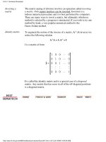
· Contact Between a Sphere and a Plane Surface
The contact area between a sphere and a plane surface, as shown in Figure 7.9, is also circular.
The contact parameters for this configuration can be calculated according to the formulae
summarized in Table 7.1.
The radii of curvature of a plane surface are infinite and symmetry of the sphere applies so
that R
bx
= R
by
= ∞ and R
ax
= R
ay
= R
A
. The reduced radius of curvature according to (7.2) is
therefore given by:
=
1
R'
+
1
R
x
=
1
R
y
+
1
R
A
+
1
∞
+
1
R
A
1
∞
=
2
R
A
(7.8)
ELASTOHYDRODYNAMIC LUBRICATION 293
Body B
R
A
W
Circular
contact area
Body A
W
a
FIGURE 7.9 Contact between a sphere and a flat surface.
where:
R
x
= R
y
= R
A
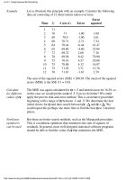
EXAMPLE
Find the contact parameters for a steel ball on a flat steel plate. The normal force is
W = 5 [N], the radius of the ball is R
A
= 10 × 10
-3
[m], the Young's modulus for ball and
plate is E = 2.1 × 10
11
[Pa] and the Poisson's ratio is υ = 0.3.
· Reduced Radius of Curvature
Since the radii of the ball and the plate are R
ax
= R
ay
= 10 × 10
-3
[m] and R
bx
= R
by
= ∞ [m]
respectively, the reduced radii of curvature in ‘x’ and ‘y’ directions are:
=
1
R
x
+
1
R
ax
1
R
bx
=
1
10 × 10
−3
+
1
∞
= 100 ⇒ R
x
= 0.01 [m]
=
1
R
y
+
1
R
ay
1
R
by
=
1
10 × 10
−3
+
1
∞
= 100 ⇒ R
y
= 0.01 [m]
Condition (7.3), i.e. 1/R
x
= 1/R
y
is satisfied (circular contact), and the reduced radius of
curvature is:
1
R'
=+
1
R
x
1
R
y
= 100 + 100 = 200 ⇒ R' = 5 × 10
−3
[m]
· Reduced Young's Modulus
E' = 2.308 × 10
11
[Pa]
294 ENGINEERING TRIBOLOGY
· Contact Area Dimensions
a =
3WR'
E'
()
1/3
=
3
× 5 × (5 × 10
−3
)
2.308 × 10
11
()
1/3
= 6.88 × 10
−5
[m]
· Maximum and Average Contact Pressures
p
max
=
3W
2πa
2
=
3 × 5
2π(6.88 × 10
−5
)
2
= 504.4 [MPa]
p
average
=
W
πa
2
=
5
π(6.88 × 10
−5
)
2
= 336.2 [MPa]
· Maximum Deflection
δ= 1.0397
W
2
E'
2
R'
()
1/3
= 1.0397
5
2
(2.308 × 10
11
)
2
5 × 10
−3
()
1/3
= 4.7 × 10
−7
[m]
· Maximum Shear Stress
τ
max
=
1
3
p
max
=
1
3
504.4 = 168.1 [MPa]
· Depth at which Maximum Shear Stress Occurs
z = 0.638a = 0.638 × (6.88 × 10
−5
) = 4.4 × 10
−5
[m]
· Contact Between Two Parallel Cylinders
The contact area between two parallel cylinders is circumscribed by a narrow rectangle. The
geometry of parallel cylinders in contact is shown in Figure 7.10 and the formulae for the
main contact parameters are summarized in Table 7.2.
T
ABLE 7.2 Formulae for contact parameters between two parallel cylinders.
b =
4WR'
πlE'
()
1/2
rectangle
p
max
=
W
πbl
Elliptical
pressure
distribution
p
average
=
W
4bl
δ= 0.319
W
E'l
()
τ
max
= 0.304p
max
at a depth of
z = 0.786b
Contact area
dimensions
Average
contact
pressure
Maximum
shear stress
Maximum
contact
pressure
Maximum
deflection
2l
2b
2
3
[)]
+ ln
(
4R
A
R
B
b
2
×
where:
b is the half width of the contact rectangle [m];
ELASTOHYDRODYNAMIC LUBRICATION 295
l is the half length of the contact rectangle [m];
R' is the reduced radius of curvature for the two parallel cylinders in contact [m].
For the cylinders: R
ax
= R
A
, R
ay
= ∞, R
bx
= R
B
, R
by
= ∞ where ‘R
A
’ and ‘R
B
’ are the
radii of the cylinders ‘A’ and ‘B’ respectively.
Substituting into equation (7.2) yields:
=
1
R'
+
1
R
x
=
1
R
y
+
1
R
A
+
1
R
B
+
1
∞
1
∞
=+
1
R
A
1
R
B
(7.9)
where:
1
R
x
=
1
R
A
+
1
R
B
and
1
R
y
= 0
The rest of the parameters are as defined for Table 7.1.
R
A
R
B
W
Rectangular
contact area
Body A
W
Body B
2b
2l
2l
2b
FIGURE 7.10 Geometry of the contact between two parallel cylinders.
EXAMPLE
Find the contact parameters for two parallel steel rollers. The normal force is W = 5 [N],
radii of the rollers are R
A
= 10 × 10
-3
[m] and R
B
= 15 × 10
-3
[m], Young's modulus for both
rollers is E = 2.1 × 10
11
[Pa] and the Poisson's ratio is υ = 0.3. The length of both rollers is
2l = 10 × 10
-3
[m].
296 ENGINEERING TRIBOLOGY
· Reduced Radius of Curvature
Since the radii of the cylinders are R
ax
= R
A
= 10 × 10
-3
[m], R
ay
= ∞ and R
bx
= R
B
= 15 × 10
-3
[m], R
by
= ∞ respectively, the reduced radii of curvature in the ‘x’ and ‘y’ directions are:
=
1
R
x
+
1
R
ax
1
R
bx
=
1
10 × 10
−3
+=166.67
1
15 × 10
−3
⇒ R
x
= 6 × 10
−3
[m]
=
1
R
y
+
1
R
ay
1
R
by
=+
1
∞
= 0
1
∞
⇒ R
y
= ∞[m]
Since 1/R
x
> 1/R
y
condition (7.3) is satisfied and the reduced radius of curvature is:
1
R'
=
1
R
x
= 166.67 ⇒ R' = 6 × 10
−3
[m]
· Reduced Young's Modulus
E' = 2.308 × 10
11
[Pa]
· Contact Area Dimensions
=
4 × 5 × (6 × 10
−3
)
π × (5 × 10
−3
) × (2.308 × 10
11
)
()
1/2
= 5.75 × 10
−6
[m]b =
4WR'
πlE'
()
1/2
· Maximum and Average Contact Pressures
p
max
=
W
πbl
=
5
π × (5.75 × 10
−6
) × (5 × 10
−3
)
= 55.4 [MPa]
p
average
=
W
4bl
=
5
4 × (5.75 × 10
−6
) × (5 × 10
−3
)
= 43.5 [MPa]
· Maximum Deflection
= 2.40 × 10
−8
[m]
δ= 0.319
W
E'l
[]
2
3
[)]
+ ln
(
4R
A
R
B
b
2
= 0.319
[]
2
3
[)]
+ ln
(
4 × (10 × 10
−3
) × (15 × 10
−3
)
(5.75 × 10
−6
)
2
5
(2.308 × 10
11
) × (5 × 10
−3
)
· Maximum Shear Stress
τ
max
= 0.304p
max
= 0.304 × 55.4 = 16.8 [MPa]
· Depth at which Maximum Shear Stress Occurs
z = 0.786b = 0.786 × (5.75 × 10
−6
) = 4.5 × 10
−6
[m]
ELASTOHYDRODYNAMIC LUBRICATION 297
· Contact Between Two Crossed Cylinders With Equal Diameters
The contact area between two cylinders with equal diameters crossed at 90° is bounded by a
circle. This configuration is frequently used in wear experiments since the contact parameters
can easily be determined. The contacting cylinders are shown in Figure 7.11 and the contact
parameters can be calculated according to the formulae summarized in Table 7.1.
Circular
contact area
a
R
B
W
Body B
W
R
A
Body A
FIGURE 7.11 Geometry of the contact between two cylinders of equal diameters with axes
perpendicular.
Since R
A
= R
B
then in this configuration R
ax
= ∞, R
ay
= R
A
, R
bx
= R
B
and R
by
= ∞. The reduced
radius according to (7.2) is given by:
=
1
R'
+
1
R
x
=
1
R
y
+
1
∞
+
1
R
B
+
1
R
A
1
∞
=
2
R
A
(7.10)
which is the same as for a sphere on a plane surface.
If the cylinders are crossed at an angle other than 0° or 90°, i.e. their axes are neither parallel
nor perpendicular, then the contact area is enclosed by an ellipse. Examples of the analysis of
such cylindrical contacts can be found in the specialized literature [14]. The formulae for
evaluation of parameters of elliptical contacts are described next.
EXAMPLE
Find the contact parameters for two steel wires of the same diameter crossed at 90°. This
configuration is often used in fretting wear studies. The normal force is W = 5 [N], radii
of the wires are R
A
= R
B
= 1.5 × 10
-3
[m], the Young's modulus for both wires is E = 2.1 ×
10
11
[Pa] and the Poisson's ratio is υ = 0.3.
298 ENGINEERING TRIBOLOGY
· Reduced Radius of Curvature
Since the radii of the wires are R
ax
= ∞, R
ay
= R
A
= 1.5 × 10
-3
[m], and R
bx
= R
B
= 1.5 × 10
-3
[m],
R
by
= ∞ respectively, the reduced radii of curvature in the ‘x’ and ‘y’ directions are:
=
1
R
x
+
1
R
ax
1
R
bx
=+
1
∞
1
1.5 × 10
−3
= 666.67 ⇒ R
x
= 0.0015 [m]
=
1
R
y
+
1
R
ay
1
R
by
=+
1
∞
= 666.67
1
1.5 × 10
−3
⇒ R
y
= 0.0015 [m]
Since 1/R
x
= 1/R
y
condition (7.3) is satisfied and the reduced radius of curvature is:
1
R'
=+
1
R
x
1
R
y
= 666.67 + 666.67 = 1333.34 ⇒ R' = 7.5 × 10
−4
[m]
· Reduced Young's Modulus
E' = 2.308 × 10
11
[Pa]
· Contact Area Dimensions
a =
3WR'
E'
()
1/3
=
3 × 5 × (7.5 × 10
−4
)
2.308 × 10
11
()
1/3
= 3.65 × 10
−5
[m]
· Maximum and Average Contact Pressures
p
max
=
3W
2πa
2
=
3 × 5
2π(3.65 × 10
−5
)
2
= 1791.9 [MPa]
p
average
=
W
πa
2
=
5
π(3.65 × 10
−5
)
2
= 1194.6 [MPa]
· Maximum Deflection
δ= 1.0397
W
2
E'
2
R'
()
1/3
= 1.0397
5
2
(2.308 × 10
11
)
2
× (7.5 × 10
−4
)
()
1/3
= 8.9 × 10
−7
[m]
· Maximum Shear Stress
τ
max
=
1
3
p
max
=
1
3
1791.9 = 597.3 [MPa]
· Depth at which Maximum Shear Stress Occurs
z = 0.638a = 0.638 × (3.65 × 10
−5
) = 2.3 × 10
−5
[m]
ELASTOHYDRODYNAMIC LUBRICATION 299
· Elliptical Contact Between Two Elastic Bodies, General Case
Elliptical contacts are found between solid bodies which have different principal relative
radii of curvature in orthogonal planes. Examples of this are encountered in spherical
bearings and gears. The contact area is described by an ellipse. An illustration of this form of
contact is shown in Figure 7.5 and the formulae for the main contact parameters are
summarized in Table 7.3.
T
ABLE 7.3 Formulae for contact parameters between two elastic bodies; elliptical contacts,
general case.
a = k
1
3WR'
E'
()
1/3
ellipse
p
max
=
3W
2πab
p
average
=
W
πab
δ= 0.52k
3
τ
max
= k
4
p
max
at a depth of
z = k
5
b
Contact area
dimensions
Average
contact
pressure
Maximum
shear stress
Maximum
contact
pressure
Maximum
deflection
a
b
b = k
2
3WR'
E'
()
1/3
Elliptical
pressure
distribution
W
2
E'
2
R'
()
1/3
≈ 0.3p
max
where:
a is the semimajor axis of the contact ellipse [m];
b is the semiminor axis of the contact ellipse [m];
R' is the reduced radius of curvature [m];
k
1
, k
2
, k
3
, k
4
, k
5
are the contact coefficients.
The other parameters are as defined previously. Contact coefficients can be found from the
charts shown in Figures 7.12 and 7.13 [13]. In Figure 7.12 the coefficients ‘k
1
’, ‘k
2
’ and ‘k
3
’ are
plotted against the ‘k
0
’ coefficient which is defined as:
k
0
=
−
1
R
ax
1
R
ay
[( )
−
1
R
bx
1
R
by
()
+
22
+ 2 −
1
R
ax
1
R
ay
()
−
1
R
bx
1
R
by
()
cos2φ
]
1/2
+
1
R
ax
(
+
1
R
ay
+
1
R
bx
1
R
by
)
where:
φ is the angle between the plane containing the minimum principal radius of
curvature of body ‘A’ and the plane containing the minimum principal radius
of curvature of body ‘B’. For example, for a wheel on a rail contact φ = 90° while
for parallel cylinders in contact φ = 0°.
The remaining contact coefficients ‘k
4
’ and ‘k
5
’ are plotted against the k
2
/k
1
ratio as shown in
Figure 7.13.
A very useful development in the evaluation of contact parameters is due to Hamrock and
Dowson [7]. The method of linear regression by the least squares method has been applied to
300 ENGINEERING TRIBOLOGY
derive simplified expressions for the elliptic integrals required for the stress and deflection
calculations in Hertzian contacts. The derived formulae apply to any contact and eliminate
the need to use numerical methods or charts such as those shown in Figures 7.12 and 7.13.
The formulae are summarized in Table 7.4. Although they are only approximations, the
differences between the calculated values and the exact predictions from the Hertzian
analysis are very small. This can easily be demonstrated by applying these formulae to the
previously considered examples, with the exception of the two parallel cylinders. In this case
the contact is described by an elongated rectangle and these formulae cannot be used. In
general, these equations can be used in most of the practical engineering applications.
1.5
2.0
0.5
1.0
1
2
5
10
0
0 0.2 0.4 0.6 0.8 1.00.1 0.3 0.5 0.7 0.9
k
0
k
3
k
2
k
1
FIGURE 7.12 Chart for the determination of the contact coefficients ‘k
1
’, ‘k
2
’ and ‘k
3
’ [13].
0.2
0.3
0.4
0.5
0.6
0.7
0.8
0 0.2 0.4 0.6 0.8 1.00.1 0.3 0.5 0.7 0.9
k
2
/k
1
k
4
& k
5
k
4
k
5
(line contact) (point contact)
FIGURE 7.13 Chart for the determination of contact coefficients ‘k
4
’ and ‘k
5
’ [13].
ELASTOHYDRODYNAMIC LUBRICATION 301
T
ABLE 7.4 Approximate formulae for contact parameters between two elastic bodies [7].
a =
6k
2
εWR'
πE'
()
1/3
ellipse
p
max
=
3W
2πab
p
average
=
W
πab
δ = ξ
Contact area
dimensions
Average
contact
pressure
Simplified
elliptical
integrals
Maximum
contact
pressure
Maximum
deflection
a
b
4.5
εR'
[( )(
1/3
b =
6εWR'
πkE'
()
1/3
W
πkE'
)
2
]
Ellipticity parameter
ε = 1.0003 +
0.5968R
x
R
y
ξ = 1.5277 + 0.6023ln
R
y
R
x
()
k = 1.0339
R
y
R
x
()
0.636
where:
ε
and
ξ
are the simplified elliptic integrals;
k is the simplified ellipticity parameter. The exact value of the ellipticity
parameter is defined as the ratio of the semiaxis of the contact ellipse in the
transverse direction to the semiaxis in the direction of motion, i.e. k = a/b.
The differences between the ellipticity parameter ‘
k
’ calculated from the
approximate formula, Table 7.4, and the ellipticity parameter calculated from
the exact formula, k = a/b, are very small [7].
The other parameters are as defined already.
EXAMPLE
Find the contact parameters for a steel ball in contact with a groove on the inside of a
steel ring (as shown in Figure 7.7). The normal force is W = 50 [N], radius of the ball is
R
ax
= R
ay
= R
A
= 15 × 10
-3
[m], the radius of the groove is R
bx
= 30 × 10
-3
[m] and the radius
of the ring is R
by
= 60 × 10
-3
[m]. The Young's modulus for both ball and ring is E = 2.1 ×
10
11
[Pa] and the Poisson's ratio is υ = 0.3.
· Reduced Radius of Curvature
Since the radii of the ball and the grooved ring are R
ax
= 15 × 10
-3
[m], R
ay
= 15 × 10
-3
[m]
and R
bx
= -30 × 10
-3
[m] (concave surface), R
by
= -60 × 10
-3
[m] (concave surface) respectively,
the reduced radii of curvature in the ‘x’ and ‘y’ directions are:
=
1
R
x
+
1
R
ax
1
R
bx
=⇒R
x
= 0.03 [m]+=33.33
1
15 × 10
−3
1
−30 × 10
−3
=
1
R
y
+
1
R
ay
1
R
by
=+ =50.0
1
15 × 10
−3
1
−60 × 10
−3
⇒ R
y
= 0.02 [m]
Since 1/R
x
< 1/R
y
condition (7.3) is not satisfied. According to the convention it is
necessary to transpose the directions of the coordinates, so ‘R
x
’ and ‘R
y
’ become:
R
x
= 0.02 [m] and R
y
= 0.03 [m]
302 ENGINEERING TRIBOLOGY
and the reduced radius of curvature is:
1
R'
=+
1
R
x
1
R
y
= 50.0 + 33.33 = 83.33 ⇒ R' = 0.012 [m]
· Reduced Young's Modulus
E' = 2.308 × 10
11
[Pa]
· Contact Coefficients
The angle between the plane containing the minimum principal radius of curvature of
the ball and the plane containing the minimum principal radius of the ring is:
φ = 0°
The contact coefficients are:
k
0
=
−
1
R
ax
1
R
ay
[( )
−
1
R
bx
1
R
by
()
+
22
+ 2 −
1
R
ax
1
R
ay
()
−
1
R
bx
1
R
by
()
cos2φ
]
1/2
+
1
R
ax
(
+
1
R
ay
+
1
R
bx
1
R
by
)
=
−
1
15 × 10
−3
1
15 × 10
−3
[( )
−
1
−60 × 10
−3
1
−30 × 10
−3
()
+
22
+ 2 −
15 × 10
−3
1
15 × 10
−3
()
−
1
−60 × 10
−3
1
−30 × 10
−3
()
cos0°
]
1/2
+
1
15 × 10
−3
(
+
1
15 × 10
−3
+
1
−60 × 10
−3
1
−30 × 10
−3
)
1
= 0.2
=
16.67
83.33
From Figure 7.12, for k
0
= 0.2:
k
1
= 1.17, k
2
= 0.88 and k
3
= 1.98
and from Figure 7.13 where k
2
/k
1
= 0.88/1.17 = 0.75, the other constants have the
following values:
k
4
= 0.33 and k
5
= 0.54
· Contact Area Dimensions
a = k
1
3WR'
E'
()
1/3
= 1.17
3 × 50 × 0.012
2.308 × 10
11
()
1/3
= 2.32 × 10
−4
[m]
b = k
2
3WR'
E'
()
1/3
= 0.88
3 × 50 × 0.012
2.308 × 10
11
()
1/3
= 1.75 × 10
−4
[m]
ELASTOHYDRODYNAMIC LUBRICATION 303
· Maximum and Average Contact Pressures
p
max
=
3W
2πab
=
3 × 50
2π(2.32 × 10
−4
) × (1.75 × 10
−4
)
= 588.0 [MPa]
p
average
=
W
πab
=
50
π(2.32 × 10
−4
) × (1.75 × 10
−4
)
= 392.0 [MPa]
· Maximum Deflection
δ= 0.52k
3
W
2
E'
2
R'
()
1/3
= 0.52 × 1.98
50
2
(2.308 × 10
11
)
2
0.012
()
1/3
= 1.6 × 10
−6
[m]
· Maximum Shear Stress
τ
max
= k
4
p
max
= 0.33 × 588.0 = 194.0 [MPa]
· Depth at which Maximum Shear Stress Occurs
z = k
5
b = 0.54 × (1.75 × 10
−4
) = 9.5 × 10
−5
[m]
It can easily be found that the Hamrock-Dowson approximate formulae (Table 7.4) give
very similar results, e.g.:
· Ellipticity Parameter
= 1.3380k = 1.0339
R
y
R
x
()
0.03
0.02
()
0.636
= 1.0339
0.636
· Simplified Elliptical Integrals
= 1.3982ε = 1.0003 +
0.5968R
x
R
y
= 1.0003 +
0.5968
× 0.02
0.03
= 1.7719ξ = 1.5277 + 0.6023ln
R
y
R
x
()
= 1.5277 + 0.6023ln
0.03
0.02
()
· Contact Area Dimensions
=
6 × 1.3380
2
× 1.3982 × 50 × 0.012
π(2.308 × 10
11
)
()
1/3
= 2.32 × 10
−4
[m]a =
6k
2
εWR'
πE'
()
1/3
= 1.73 × 10
−4
[m]
b =
6εWR'
πkE'
()
1/3
=
6 × 1.3982 × 50 × 0.012
π × 1.3380 × (2.308 × 10
11
)
()
1/3
304 ENGINEERING TRIBOLOGY
· Maximum and Average Contact Pressures
p
max
=
3W
2πab
=
3 × 50
2π(2.32 × 10
−4
) × (1.73 × 10
−4
)
= 594.8 [MPa]
p
average
=
W
πab
=
50
π(2.32 × 10
−4
) × (1.73 × 10
−4
)
= 396.5 [MPa]
· Maximum Deflection
= 1.7719 = 1.6 × 10
−6
[m]
δ = ξ
4.5
εR'
[( )(
1/3
W
πkE'
)
2
]
4.5
1.3982 × 0.012
[( )(
1/3
50
π1.3380 × (2.308 × 10
11
)
)
2
]
When comparing the results obtained by the Hertz theory and the Hamrock-Dowson
approximation it is apparent that the differences between the results obtained by both
methods are very small. Errors due to the approximation on reading values of contact
coefficients from Figures 7.12 and 7.13 may contribute significantly to the difference.
The benefits of applying the Hamrock-Dowson formulae to the evaluation of contact
parameters are demonstrated by the simplification of the calculations without any
compromise in accuracy. Hence the Hamrock-Dowson formulae can be used with confidence
in most practical engineering applications.
Total Deflection
In some practical engineering applications, such as rolling bearings, the rolling element is
squeezed between the inner and outer ring and the total deflection is the sum of the
deflections between the element and both rings, i.e.:
δ
T
= δ
o
+ δ
i
(7.11)
where:
δ
T
is the total combined deflection between the rolling element and the inner and
outer rings [m];
δ
o
is the deflection between the rolling element and the outer ring [m];
δ
i
is the deflection between the rolling element and the inner ring [m].
According to the formula from Table 7.4, the maximum deflections for the inner and outer
conjunctions can be written as:
δ
i
= ξ
i
4.5
ε
i
R
i
'
[( )(
1/3
W
πk
i
E'
)
2
]
(7.12)
δ
o
= ξ
o
4.5
ε
o
R
o
'
[( )(
1/3
W
πk
o
E'
)
2
]
ELASTOHYDRODYNAMIC LUBRICATION 305
where ‘i’ and ‘o’ are the indices referring to the inner and outer conjunction respectively.
Note that each of these conjunctions has a different contact geometry resulting in a different
reduced radius ‘R'’, ellipticity parameter ‘
k’ and simplified integrals ‘
ξ
’ and ‘
ε
’ .
Introducing coefficients which are a function of the contact geometry and material properties,
i.e.:
K
i
= πk
i
E'
4.5ξ
i
3
()
ε
i
R
i
'
1/2
(7.13)
K
o
= πk
o
E'
4.5ξ
o
3
()
ε
o
R
o
'
1/2
The deflections can be written as:
δ
i
=
()
W
2/3
K
i
δ
o
=
()
W
2/3
K
o
and
δ
T
=
()
W
2/3
K
T
Substituting into equation (7.11) yields:
=
()
W
2/3
()
W
2/3
+
()
W
2/3
K
T
K
o
K
i
(7.14)
By rearranging the above expression the coefficient ‘
K
T
’ for the total combined deflection, in
terms of the ‘
K
i’ and ‘
K
o
’ coefficients, can be obtained [7], i.e.:
=
1
[(()
1
2/3
+
()
1
2/3
]
3/2
K
T
K
o
K
i
(7.15)
It should be realized that the deflections and furthermore the pressures resulting from
different loads cannot be superimposed. This is because Hertzian deflections are not linear
functions of load.
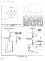
7.4 ELASTOHYDRODYNAMIC LUBRICATING FILMS
The term elastohydrodynamic lubricating film refers to the lubricating oil which separates
the opposing surfaces of a concentrated contact. The properties of this minute amount of oil,
typically 1 [µm] thick and 400 [µm] across for a point contact, and which is subjected to
extremes of pressure and shear, determine the efficiency of the lubrication mechanism under
rolling contact.
306 ENGINEERING TRIBOLOGY
Effects Contributing to the Generation of Elastohydrodynamic Films
The three following effects play a major role in the formation of lubrication films in
elastohydrodynamic lubrication:
· the hydrodynamic film formation,
· the modification of the film geometry by elastic deformation,
· the transformation of the lubricant's viscosity and rheology under pressure.
All three effects act simultaneously and cause the generation of elastohydrodynamic films.
· Hydrodynamic Film Formation
The geometry of interacting surfaces in Hertzian contacts contains converging and diverging
wedges so that some form of hydrodynamic lubrication occurs. The basic principles of
hydrodynamic lubrication outlined in Chapter 4 apply, but with some major differences.
Unlike classical hydrodynamics, both the contact geometry and lubricant viscosity are a
function of hydrodynamic pressure. It is therefore impossible to specify precisely a film
geometry and viscosity before proceeding to solve the Reynolds equation. Early attempts by
Martin [2] were made, for example, to estimate the film thickness in elastohydrodynamic
contacts using a pre-determined film geometry, and erroneously thin film thicknesses were
predicted.
· Modification of Film Geometry by Elastic Deformation
For all materials whatever their modulus of elasticity, the surfaces in a Hertzian contact
deform elastically. The principal effect of elastic deformation on the lubricant film profile is
to interpose a central region of quasi-parallel surfaces between the inlet and outlet wedges.
This geometric effect is shown in Figure 7.14 where two bodies, i.e. a flat surface and a roller,
in elastic contact are illustrated. The contact is shown in one plane and the contact radii are
‘∞’ and ‘R’ for the flat surface and roller respectively.
x
h
f
h
e
B
W
R
U
h
g
=
x
2
2R
y
h
e
A
Body A
Body B
FIGURE 7.14 Effects of local elastic deformation on the lubricant film profile.
The film profile in the ‘x’ direction is given by [15]:
ELASTOHYDRODYNAMIC LUBRICATION 307
h = h
f
+ h
e
+ h
g
where:
h
f
is constant [m];
h
e
is the combined elastic deformation of the solids [m], i.e. h
e
= h
e
A
+ h
e
B
;
h
g
is the separation due to the geometry of the undeformed solids [m], i.e. for the
ball on a flat plate shown in Figure 7.14 h
g
= x
2
/2R;
R is the radius of the ball [m].
· Transformation of Lubricant Viscosity and Rheology Under Pressure
The non-conformal geometry of the contacting surfaces causes an intense concentration of
load over a very small area for almost all Hertzian contacts of practical use. When a liquid
separates the two surfaces, extreme pressures many times higher than those encountered in
hydrodynamic lubrication are inevitable. Lubricant pressures from 1 to 4 [GPa] are found in
typical machine elements such as gears. As previously discussed in Chapter 2, the viscosity of
oil and many other lubricants increases dramatically with pressure. This phenomenon is
known as piezoviscosity. The viscosity-pressure relationship is usually described by a
mathematically convenient but approximate equation known as the Barus law:
η
p
= η
0
e
αp
where:
η
p
is the lubricant viscosity at pressure ‘p’ and temperature ‘θ’ [Pas];
η
0
is the viscosity at atmospheric pressure and temperature ‘θ’ [Pas];
α is the pressure-viscosity coefficient [m
2
/N].
As an example of the radical effect of pressure on viscosity, it has been reported that at contact
pressures of about 1 [GPa], the viscosity of mineral oil may increase by a factor of 1 million
(10
6
) from its original value at atmospheric pressure [15].
With sufficiently hard surfaces in contact, the lubricant pressure may rise to even higher
levels and the question of whether there is a limit to the enhancement of viscosity becomes
pertinent. The answer is that indeed there are constraints where the lubricant loses its liquid
character and becomes semi-solid. This aspect of elastohydrodynamic lubrication is the focus
of present research and is discussed later in this chapter. For now, however, it is assumed
that the Barus law is exactly applicable.
Approximate Solution of Reynolds Equation With Simultaneous Elastic Deformation and
Viscosity Rise
An approximate solution for elastohydrodynamic film thickness as a function of load, rolling
speed and other controlling variables was put forward by Grubin and was later superseded by
more exact equations. Grubin's expression for film thickness is, however, relatively accurate
and the same basic principles that were originally established have been applied in later
work. For these reasons, Grubin's equation is derived in this section to illustrate the
principles of how the elastohydrodynamic film thickness is determined.
The derivation of the film thickness equation for elastohydrodynamic contacts begins with
the 1-dimensional form of the Reynolds equation without squeeze effects (i.e. 4.27):
308 ENGINEERING TRIBOLOGY
dp
dx
= 6Uη
h − h
h
3
()
where the symbols follow the conventions established in Chapter 4 and are:
p is the hydrodynamic pressure [Pa];
U is the surface velocity [m/s];
η is the lubricant viscosity [Pas];
h is the film thickness [m];
h is the film thickness where the pressure gradient is zero [m];
x is the distance in direction of rolling [m].
Substituting into the Reynolds equation the expression for viscosity according to the Barus
law yields:
dp
dx
= 6Uη
0
e
αp
h − h
h
3
()
(7.16)
To solve this equation, Grubin introduced an artificial variable, known as the ‘reduced
pressure’, defined as:
q =
()
1
α
1 − e
−αp
(7.17)
Differentiating gives:
dq
dx
= e
−αp
dp
dx
When this term is substituted into the Reynolds equation (7.16), a separation of pressure and
film thickness is achieved:
dq
dx
= 6Uη
0
h − h
h
3
()
(7.18)
Two independent controlling variables, i.e. ‘x’ and ‘h ’, however, still remain and
replacement of either of these variables by the other (since x = f(h)) is required for the
solution. The argument used to achieve this reduction in unknown variables is perhaps the
most original and innovative part of Grubin's analysis.
Grubin observed that at the inlet of the EHL contact, the contact pressure rises very sharply as
predicted by Hertzian contact theory. If a hydrodynamic film is established, then the
hydrodynamic pressure should also rise sharply at the inlet. This sharp rise in pressure can
be approximated as a step jump to some value in pressure comparable to the peak Hertzian
contact pressure. If this pressure is assumed to be large enough then the term e
−αp
« 1 and it
can be seen from equation (7.17) that q ≈ 1/α. Grubin reasoned that since the stresses and the
deformations in the EHL contacts were substantially identical to Hertzian, the opposing
surfaces must almost be parallel and thus the film thickness is approximately uniform
within the contact. Inside the contact therefore, the film thickness h = constant so that h =
h.
ELASTOHYDRODYNAMIC LUBRICATION 309
Since ‘
h
’ occurs where ‘p
max
’ takes place Grubin deduced that there must be sharp increase in
pressure in the inlet zone to the contact as shown in Figure 7.15. It therefore follows that
according to this model q ≈ 1/α = constant, dq/dx = 0 and h =
h within the contact.
Grubin’s model of
contact pressure
p
max
p
Hertzian
pressure
BODY A
BODY B
Steep pressure
jump at inlet
h
¯
FIGURE 7.15 Grubin's approximation to film thickness within an EHL contact.
A formal expression for ‘q’ is found by integrating (7.18);
q = 6Uη
0
⌠
⌡
h
∞
h
1
dx
h − h
h
3
()
(7.19)
where:
h
1
is the inlet film thickness to the EHL contact [m];
h
∞
is the film thickness at a distance ‘infinitely’ far from the contact [m].
Since q ≈ 1/α the above equation (7.19) can be written in the form:
⌠
⌡
h
∞
h
1
q ==6Uη
0
1
α
dx
h − h
h
3
()
(7.20)
After replacing one variable with another (i.e. expressing ‘x’ in terms of ‘h’), this integral is
solved numerically by assuming that the values of film thickness ‘h’ are equal to the distance
separating the contacting dry bodies plus the film thickness within the EHL contact. The
constant of integration is zero for the selected limits of this integral since at any position
remote from the contact, p = 0 and therefore q = 0. The following approximation was
calculated numerically for the integral as applied to a line contact:
dx = 0.131
LE'R'
()
W
−0.625
R'
2
()
b
R'
()
h
−1.375
⌠
⌡
h
∞
h
1
h − h
h
3
()
(7.21)
where:
R' is the reduced radius of curvature [m];
E' is the reduced Young's modulus [Pa];
L is the full length of the EHL contact, i.e. L = 2l, [m];
310 ENGINEERING TRIBOLOGY
b is the half width of the EHL contact [m];
h is the film thickness where the pressure gradient is zero, i.e. Grubin's EHL film
thickness as shown in Figure 7.15 [m];
W is the contact load [N].
Rearranging (7.20) gives:
⌠
⌡
h
∞
dx =
6Uη
0
α
1
h
1
h − h
h
3
()
(7.22)
The integral term is then eliminated by substituting equation (7.22) into equation (7.21), i.e.:
1.275
LE'R'
()
W
0.625
bUη
0
α
R'
2
=
R'
()
h
−1.375
(7.23)
Expressing equation (7.23) as a unit power of h
/
R' yields:
= 1.193
R'
()
h
bUη
0
α
R'
2
()
−0.7273
LE'R'
()
W
−0.4545
(7.24)
Substituting for contact width ‘b’ the Hertzian contact formula (Table 7.2) yields a more
convenient expression for routine film thickness calculation. The expression for ‘b’ (Table
7.2) is:
b =
πlE'
()
4WR'
1/2
=
πLE'
()
8WR'
1/2
Substituting into (7.24) gives Grubin's expression for film thickness in the
elastohydrodynamic linear contact, i.e.:
= 1.657
R'
()
h
R'
Uη
0
α
()
0.7273
LE'R'
()
W
−0.0909
(7.25)
It can be seen that all the variables are combined in dimensionless groups making the
interpretation of the irrational exponents easier.
Grubin was able to demonstrate with the above expression that oil films with sufficient
thickness to separate typical engineering surfaces existed in concentrated line contacts. The
values of film thickness provided by this approximate formula are surprisingly accurate. The
relative effects of load, rolling velocity and pressure-viscosity dependence are shown in
terms of indices that correspond closely to more exact analyses. The comparatively weak
effect of load should be noted which explains the high load-capacity of elastohydrodynamic
films. More advanced solutions of the elastohydrodynamic film thickness equation involve
the 2-dimensional Reynolds equations and more sophisticated inlet conditions. Grubin also
assumed that the contact was 'fully flooded', i.e. the rolling elements moved in a bath of oil.
More exact work has allowed for the effect of oil shortage in the contact and thermal effects at
high speeds. The exact analysis of elastohydrodynamic lubrication involves a simultaneous
ELASTOHYDRODYNAMIC LUBRICATION 311
iterative numerical solution of the equations describing hydrodynamic film formation,
elastic deformation and piezoviscosity in a lubricated Hertzian contact. These are the same
fundamental equations which are described above, but they are solved directly without any
analytical simplifications. The numerical procedures and mathematics involved are
described in detail in [7,11].
Pressure Distribution in Elastohydrodynamic Films
In a static contact, the pressure distribution is hemispherical or ellipsoidal in profile
according to classical Hertzian theory. The pressure field will change, however, when the
surfaces start moving relative to each other in the presence of a piezoviscous lubricant such
as oil. Relative motion between the two surfaces causes a hydrodynamic lubricating film to
be generated which modifies the pressure distribution to a certain extent. The greatest
changes to the pressure profile occur at the entry and exit regions of the contact. The
combined effect of rolling and a lubricating film results in a slightly enlarged contact area.
Consequently at the entry region, the hydrodynamic pressure is lower than the value for a
dry Hertzian contact. This has been demonstrated in numerous experiments. The opposing
surfaces within the contact are almost parallel and planar and film thickness is often
described in this region by the central film thickness ‘h
c
’. The lubricant experiences a
precipitous rise in viscosity as it enters the contact followed by an equally sharp decline to
ambient viscosity levels at the exit of the contact. To maintain continuity of flow and
compensate for the loss of lubricant viscosity at the contact exit, a constriction is formed close
to the exit. The minimum film thickness ‘h
0
’ is found at the constriction as shown in Figure
7.16. The minimum film thickness is an important parameter since it controls the likelihood
of asperity interaction between the two surfaces. Viscosity declines even more sharply at the
exit than at the entry to the contact. A large pressure peak is generated next to the constriction
on the upstream side, and downstream the pressure rapidly declines to less than dry Hertzian
values. The peak pressure is usually larger than the maximum Hertzian contact pressure and
diminishes as the severity of lubricant starvation increases and dry conditions are
approached [7]. The size and the steepness of the pressure peak depends strongly on the
lubricant's pressure-viscosity characteristics.
h
0
h
c
Constriction
Contacting
surfaces
p
Hertzian
pressure
distribution
U
Elastohydrodynamic
pressure
distribution
FIGURE 7.16 Hydrodynamic pressure distribution in an elastohydrodynamic contact; h
c
is the
central film thickness, h
0
is the minimum film thickness.
The end constriction to the EHL film is even more distinctive for a ‘point’ contact, e.g. two
steel balls in contact. In this case the contact is circular and the end constriction has to be
312 ENGINEERING TRIBOLOGY
curved in order to fit into the contact boundary. This effect is known as the ‘horse-shoe’
constriction and is shown later in Figure 7.22 which illustrates a plan view of the EHL film
(as opposed to the side view shown in Figure 7.16). The minimum film thickness in a point
contact is found at both ends of the ‘horse-shoe’ and at these locations the film thickness is
only about 60% of its central value.
Elastohydrodynamic Film Thickness Formulae
The exact analysis of elastohydrodynamic lubrication by Hamrock and Dowson [7,16]
provided the most important information about EHL. The results of this analysis are the
formulae for the calculation of the minimum film thickness in elastohydrodynamic contacts.
The formulae derived by Hamrock and Dowson apply to any contact, such as point, linear or
elliptical, and are now routinely used in EHL film thickness calculations. They can be used
with confidence for many material combinations including steel on steel even up to
maximum pressures of 3-4 [GPa] [11]. The numerically derived formulae for the central and
minimum film thicknesses, as shown in Figure 7.16, are in the following form [7]:
= 2.69
R'
h
c
E'R'
()
Uη
0
0.67
()
0.53
αE'
E'R'
2
()
W
−0.067
()
1 − 0.61e
−0.73k
(7.26)
= 3.63
R'
h
0
E'R'
()
Uη
0
0.68
()
0.49
αE'
E'R'
2
()
W
−0.073
()
1 − e
−0.68k
(7.27)
where:
h
c
is the central film thickness [m];
h
0
is the minimum film thickness [m];
U is the entraining surface velocity [m/s], i.e. U = (U
A
+ U
B
)/2, where the subscripts
‘A’ and ‘B’ refer to the velocities of bodies ‘A’ and ‘B’ respectively;
η
0
is the viscosity at atmospheric pressure of the lubricant [Pas];
E' is the reduced Young's modulus (7.6) [Pa];
R' is the reduced radius of curvature [m];
α is the pressure-viscosity coefficient [m
2
/N];
W is the contact load [N];
k is the ellipticity parameter defined as: k = a/b, where ‘a’ is the semiaxis of the
contact ellipse in the transverse direction [m] and ‘b’ is the semiaxis in the
direction of motion [m].
As mentioned already, the approximate value of the ellipticity parameter can be calculated
with sufficient accuracy from:
k = 1.0339
R
x
()
R
y
0.636
where:
R
x
, R
y
are the reduced radii of curvature in the ‘x’ and ‘y’ directions respectively.
ELASTOHYDRODYNAMIC LUBRICATION 313
It can be seen that for line contacts k = ∞ and for point contact k = 1. It has been shown that
the above EHL film thickness equations are applicable for ‘k’ values between 0.1 and ∞ [17].
The non-dimensional groups in equations (7.26) and (7.27) are frequently referred to in the
literature as:
· the non-dimensional film parameter
=
H
R'
h
· the non-dimensional speed parameter
=
E'R'
()
Uη
0
U
· the non-dimensional materials parameter
= (αE')
G
· the non-dimensional load parameter
=
E'R'
2
()
W
W
· the non-dimensional ellipticity parameter
k =
b
a
Effects of the Non-Dimensional Parameters on EHL Contact Pressures and Film Profiles
The changes in the non-dimensional parameters have varying effects on the EHL film
thicknesses and pressures. To demonstrate these effects, Hamrock and Dowson allowed one
specific parameter to vary while holding all the other parameters constant [7].
· Effect of the Speed Parameter
As would be expected from the need for relative movement to generate a hydrodynamic
pressure field, the speed parameter has a strong effect on EHL. The influence of the speed
parameter ‘U’ on the pressure and film thickness profiles is shown in Figure 7.17. The
pressure and film profiles are calculated for: k = 6, W = 7.371
× 10
-7
and G = 4.522 × 10
3
[7].
It can be seen that in the inlet region there is a gradual increase in pressure with speed and a
corresponding decline in pressure in the outlet region of the Hertzian contact area. The effect
of elevated speed is to radically distort the pressure profile from the Hertzian form to the
profile of a sharply pointed peak. This change in pressure profile increases the maximum
contact pressure for a given load which may cause damage to the underlying material. When
the speed parameter is reduced, the pressure profile reverts to the Hertzian form, but with a
pressure peak at the exit constriction. The effect of the speed parameter on the film thickness
profile is to (a) increase film thickness, (b) reduce the proportion of contact area where the
two surfaces are virtually parallel, and (c) increase the proportion of contact area covered by
the exit constriction. The first effect, i.e. increase in the film thickness, is the most significant;
while the importance of the other effects is unclear. It is evident that the film thickness
varies considerably with speed, which illustrates the dominant effect of the non-dimensional
speed parameter on the minimum film thickness in elastohydrodynamic contacts.
These findings have been confirmed experimentally by many researchers. The experiments
usually demonstrated a remarkable agreement with theory. The pressure distribution,
position of the pressure peak and film profile could be accurately and effectively predicted at
a particular velocity and load. There was, however, some discrepancy concerning the height
314 ENGINEERING TRIBOLOGY
of the pressure peak since the measured peak was very much smaller than that predicted by
theory. This was eventually rectified by introducing the lubricant compressibility into the
calculations which resulted in a reduction in the pressure spike [18].
-2 -1 0 1
x =
x
b
0
0
0.0005
0.0010
0.0015
Dimensionless
film thickness
H =
h
R'
Dimensionless
pressure
p* =
p
E'
0.0020
Dimensionless
speed parameter
Maximum
Hertzian
Stress
Dimensionless
speed parameter
U = 5.0500 × 10
-11
0.8416 × 10
-11
0.8416 × 10
-12
U = 5.0500 × 10
-11
0.8416 × 10
-11
0.8416 × 10
-12
20 × 10
−6
40 × 10
−6
60 × 10
−6
80 × 10
−6
100 × 10
−6
FIGURE 7.17 Effects of speed parameter ‘U’ on the pressure and film thickness in an EHL
contact; b is the semiaxis of the contact ellipse in the direction of motion [7].
· Effect of the Materials Parameter
In general terms, the type of materials used will determine the regime of hydrodynamic
lubrication, whether it is true EHL or some other variant. For example, substituting rubber
for steel reduces the contact stress sufficiently to preclude the pressure dependent viscosity
rise found in EHL. It is, however, difficult to show the effect of small variations of the
materials parameter on EHL since the dimensioned parameters defining the materials
parameter, such as the reduced Young's modulus, are also included in the non-dimensional
load and speed parameters. The minimum film thickness as a function of the material
properties and these other parameters can be written as [7]:
H
min
α G
0.45
· Effect of Load Parameter
Load also has a strong effect on film thickness in general and more importantly on the
minimum film thickness at the exit constriction. Figure 7.18 shows the effect of varying load
parameter on hydrodynamic pressure and film thickness for constant values of ellipticity,
speed parameter and materials parameter: k = 6, U = 1.683
× 10
-12
, G = 4.522 × 10
3
[7].
ELASTOHYDRODYNAMIC LUBRICATION 315
-2 -1 0 1
0
0.0005
0.0010
0.0015
Dimensionless
film thickness
H =
h
R'
Dimensionless
pressure
Dimensionless
load
W = 1.1060 × 10
-6
0.5528 × 10
-6
p* =
p
E'
10 × 10
−6
15 × 10
−6
20 × 10
−6
0.1106 × 10
-6
Dimensionless
load
W = 1.1060 × 10
-6
0.5528 × 10
-6
0.1106 × 10
-6
x =
x
b
FIGURE 7.18 Effects of load parameter on pressure and film thickness in EHL contacts; b is as
defined previously [7].
It can be seen that as the load is increased, hydrodynamic pressure becomes almost
completely confined inside the nominal Hertzian contact area. This effect is so strong that
with an increase in load, pressure outside the contact area, i.e. at the inlet, actually declines.
The increase in load also causes an increase in film thickness between the inlet and exit
constriction which is a re-entrant profile. This feature is attributed to lubricant
compressibility [7].
It is evident that the central film thickness declines with load till a certain level where film
thickness becomes virtually independent of load. This is a very useful feature of EHL but it
should also be noted that the minimum film thickness at the constriction does not decline
significantly with increased load.
· Effect of Ellipticity Parameter
Ellipticity has a strong effect on the hydrodynamic pressure profile and film thickness. Figure
7.19 shows pressure and film thickness profiles for ‘k’ ranging from 1.25 to 6 for the following
values of the non-dimensional controlling parameters: U = 1.683
× 10
-12
, W = 1.106 × 10
-7
and
G = 4.522
× 10
3
[7]. The profile is shown for a section codirectional with the rolling velocity.
The pressure ‘spike’ is predicted for k = 1.25 and 2.5 but not for k = 6. The film thickness
appears to increase in proportion to ‘k’ and this trend is due to the relative widening of the
contact which enhances the generation of hydrodynamic pressure for a given film thickness
by preventing side leakage of lubricant. The re-entrant form of the film profile when k = 1.25
is attributed to lubricant compressibility. When the compressibility is considered, the local
film thickness is reduced by an amount corresponding to the change in fluid volume with
pressure.