Máy xúc lất HuynDai HL760 - Chapter 3
Bạn đang xem bản rút gọn của tài liệu. Xem và tải ngay bản đầy đủ của tài liệu tại đây (6.83 MB, 32 trang )
7-21
The speedometer displays the speed of machine in mph and
km/h.
The unit (The unit (
km/h km/h
oror
mph mph
) can be set by the display set up menu ) can be set by the display set up menu
of the monitor and selected unit is displayed.of the monitor and selected unit is displayed.
Refer to page 7-42.Refer to page 7-42.
Speedometer
Fuel gauge
LCD (See page 7-29)
T/M oil temperature gauge
Hyd oil temp gauge
Engine coolant temperature gauge
Emergency warning lamp
Left turning pilot lamp
Right turning pilot lamp
Lamps (See page 7-23,26)
Battery volt meter
Lamps (See page 7-23,26)
Unit
①
※
75797EL55
75793CD03
SpeedometerSpeedometer
(1)(1)
GAUGEGAUGE
2)2)
GROUP 3 MONITORING SYSTEMGROUP 3 MONITORING SYSTEM
1. 1. CLUSTER CLUSTER
STRUCTURESTRUCTURE
The cluster consists of gauges, lamps and LCD as shown below, to warn the operator in case of
abnormal machine operation or conditions for the appropriate operation and inspection.
·
Gauges
: Indicate operating status of the machine.
·
Warning lamps : Indicate abnormality of the machine.
·
Pilot lamps : Indicate operating status of the machine.
·
LCD : Indicates selected the driving speed and direction.
※
The cluster installed on this machine does not entirely guarantee the condition of the The cluster installed on this machine does not entirely guarantee the condition of the
machine. Daily inspection should be performed according to chapter 6, Mmachine. Daily inspection should be performed according to chapter 6, MAINTENANCE AINTENANCE
in operator's manual.in operator's manual.
※
When the cluster provides a warning immediately check the problem, and perform the When the cluster provides a warning immediately check the problem, and perform the
required action.required action.
1)1)
7-22
Red
Red
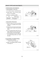
White
This gauge indicates the amount of fuel in the fuel tank.
Fill the fuel when the indicator moves red range or lamp blinks
in red, refuel as soon as possible to avoid running out of fuel.
If the gauge indicates below red range even though the If the gauge indicates below red range even though the
machine is on the normal condition, check the electric device machine is on the normal condition, check the electric device
as that can be caused by the poor connection of electricity or as that can be caused by the poor connection of electricity or
sensor.sensor.
①
②
※
This gauge indicates the temperature of coolant.
·
White range : 40~104
˚
C (104~219˚F)
·
Red range : Above 104
˚
C (21
9
˚F)
If the indicator is in the red range or lamp blinks in red, turn
OFF the engine and check the radiator and engine.
①
②
75793CD04
75793CD05
Fuel gaugeFuel gauge
(2)(2)
Engine coolant temperature gaugeEngine coolant temperature gauge
(3)(3)
Red
White
This gauge indicates the temperature of transmission oil.
·
White range : 40~107
˚
C (104~225˚F)
·
Red range : Above 107
˚
C (22
5
˚F)
If the indicator is in the red range or lamp blinks in red, it
means the transmission is overheated. Be careful that the indi-
cator does not move into the red range.
①
②
20V 36V
30V
24V
This gauge indicates the voltage in the charging system when
the engine is running.
If the indicator is below 24V, it means that the electricity is being
discharged. If the indicator is above 30V, an unusually high volt-
age may damage the alternator. Check the charging system in
both cases.
①
②
75793CD06
75793CD07
This gauge indicates the temperature of hydraulic oil.
·
White range : 40~105
˚
C (104~221˚F)
·
Red range : Above 105
˚
C (22
1
˚F)
If the indicator is in the red range or lamp blinks in red, reduce
the load on the system.
If the gauge stays in the red range, stop the machine and check
the cause of the problem.
Red
White
①
②
③
75793CD08
Transmission oil temperature gaugeTransmission oil temperature gauge
(4)(4)
Battery volt meterBattery volt meter
(6)(6)
Hyd oil temperature gaugeHyd oil temperature gauge
(5)(5)
7-23
This warning lamp blinks and the buzzer sounds when comuni-
cation error occur between monitor and MCU.
When this warning lamp blinks, machine must be checked and
service immediately.
①
②
75793CD95
WARNING LAMPSWARNING LAMPS
3)3)
Emergency warning lamp
Engine overheat warning lamp
T/M oil temperature warning lamp
Hydraulic oil temperature
warning lamp
Fuel level warning lamp
T/M error warning lamp
Air cleaner warning lamp
Engine oil pressure warning lamp
Steering warning lamp(Primary)
Steering warning lamp(Emergency)
Brake fail warning lamp
Battery charging warning lamp
75793CD09
This lamp is turned ON when the temperature of coolant is over
the normal temperature 104
˚
C (219
˚
F).
Check the cooling system when the lamp is ON.
①
②
77073CD17
This lamp informs the operator that transmission oil is above the
specified temperature.
When this lamp lights up during operation, stop the engine and
check the machine.
①
②
75793CD35
Emergency warning lampEmergency warning lamp
(1)(1)
Engine overheat warning lampEngine overheat warning lamp
(2)(2)
Transmission oil temperature warning lampTransmission oil temperature warning lamp
(3)(3)
7-24
This lamp lights ON and the LCD display show the error codes
when an error occurs in the transmission.
Immediately pull the machine to a convenient stop. Stop the
engine. Investigate the cause.
Consult a HYUNDAI dealer to investigate the cause.Consult a HYUNDAI dealer to investigate the cause.
Do not operate until the cause has been corrected.Do not operate until the cause has been corrected.
①
②
※
※
This lamp lights ON when the filter of air cleaner is clogged.
Check the filter and clean or replace it when the lamp is ON.
①
②
This warning lamp operates and the buzzer sounds when the
temperature of hydraulic oil is over 105
˚
C (221
˚
F).
Check the hydraulic oil level when the lamp is turned ON.
Check for debris between oil cooler and radiator.
①
②
③
This lamp is comes ON after starting the engine because of the
low engine oil pressure.
If the lamp comes ON during engine operation, shut OFF engine
immediately. Check engine oil level.
①
②
This warning lamp lights ON when the fuel level is low.
Refuel the machine as soon as possible.
①
77073CD18
77073CD19
77073CD20
77073CD21
77073CD23
Hydraulic oil temperature warning lampHydraulic oil temperature warning lamp
(4)(4)
Fuel level warning lampFuel level warning lamp
(5)(5)
Transmission error warning lampTransmission error warning lamp
(6)(6)
Air cleaner warning lampAir cleaner warning lamp
(7)(7)
Engine oil pressure warning lampEngine oil pressure warning lamp
(8)(8)
7-25
The lamp lights ON when the oil pressure of service brake drops
below the normal range.
When the lamp is ON, stop the engine and check for its cause.
Do not operate until any problems are corrected.Do not operate until any problems are corrected.
①
②
※
This lamp is ON when key ON, it is turned OFF after starting the
engine.
Check the battery charging circuit when this lamp comes ON,
during engine operation.
①
②
77073CD16
77073CD22
PrimaryPrimary
This lamp indicates that the primary steering has failed. When
the indicator comes on and the action alarm sounds, steer the
machine immediately to a convenient location and stop the
machine. Stop the engine and investigate the cause.
Do not operate the machine until the cause has been cor-Do not operate the machine until the cause has been cor-
rected.rected.
EmergencyEmergency
This lamp indicates the emergency steering system is active.
Immediately pull the machine to a convenient stop and stop Immediately pull the machine to a convenient stop and stop
the engine.the engine.
The emergency steering system can be manually tested. The emergency steering system can be manually tested.
Refer to page 7-47.Refer to page 7-47.
①
※
②
※
※
77073CD66
77073CD15
Steering warning lampSteering warning lamp
(9)(9)
Battery charging warning lampBattery charging warning lamp
(10)(10)
Brake fail warning lampBrake fail warning lamp
(11)(11)
7-26
PILOT LAMPSPILOT LAMPS
4)4)
Warming up pilot lamp
Mirror defrost pilot lamp
Preheater pilot lamp
Maintenance pilot lamp
FNR select pilot lamp
Clutch cut off pilot lamp
Ride control pilot lamp(Auto)
Ride control pilot lamp(On)
Seat belt pilot lamp
High beam pilot lamp
Parking brake pilot lamp
Joystick steering pilot lamp
Fan reverse pilot lamp
75793CD10
This lamp is turned ON when the coolant temperature is below
30
˚
C (86
˚
F).
The automatic warming up is cancelled when the engine coolant
temperature is above 30
˚
C, or when 10 minutes have passed
since starting the engine.
①
②
75793CD31
Warming up pilot lampWarming up pilot lamp
(1)(1)
This lamp lights ON for the first five seconds after starting the
engine.
①
75793CD17
Seat belt pilot lampSeat belt pilot lamp
(2)(2)
This lamp comes ON when mirror defrost switch is pressed.
①
7807A3CD11
Mirror defrost pilot lampMirror defrost pilot lamp
(3)(3)
7-27
This lamp works when the illuminating direction is upward.
This lamp comes ON when the dimmer switch is operated, e.g.,
when passing another vehicle.
①
②
When the parking brake is actuated, the lamp lights ON.
Check the lamp is OFF before driving.Check the lamp is OFF before driving.
①
※
77073CD12
77073CD13
This lamp lights ON when start switch is turned clockwise to the
ON position. Light will turn off after approximately 5~45 sec-
onds, depending on engine temperature, indicating that preheat-
ing is completed.
When the lamp goes out the operator should start cranking the
engine.
①
②
77073CD14
This lamp will be ON when the consuming parts are needed
to change or replace. It means that the change or replace-
ment interval of the consuming parts remains below 30
hours.
Check the message in maintenance information of the moni-
tor menu. Also, this lamp lights ON for 3 minutes when the
start switch is ON position.
①
②
75793CD32
High beam pilot lampHigh beam pilot lamp
(4)(4)
Preheat pilot lampPreheat pilot lamp
(5)(5)
Parking brake pilot lampParking brake pilot lamp
(6)(6)
Maintenance pilot lampMaintenance pilot lamp
(7)(7)
This lamp lights ON when the clutch cut off mode switch is
positioned L, M, H.
ReferRefer to page 7-48. to page 7-48.
①
※
77073CD65
Clutch cut off pilot lampClutch cut off pilot lamp
(8)(8)
7-28
The lamp comes ON when FNR select button on the optional
FNR remote control lever is pressed.
①
7807A3CD24
This lamp lights ON when joystick steering is activated.
It is then possible to steer the machine and select gears from the
armrest to the left of the operator's seat.
①
77073CD41
Auto ride controlAuto ride control
This lamp lights ON when push in the bottom of the ride control
switch (auto position).
Refer to page 7-47.Refer to page 7-47.
①
※
75793CD33
FNR select pilot lampFNR select pilot lamp (option)
(9)(9)
Joystick steering pilot lampJoystick steering pilot lamp (option)
(10)(10)
Ride control pilot lampRide control pilot lamp (option)
(11)(11)
This lamp lights ON when the fan control switch is pressed.
Refer to page 7-46.Refer to page 7-46.
①
※
7707A3CD40
Fan reverse pilot lampFan reverse pilot lamp
(12)(12)
Manual ride controlManual ride control
This lamp lights ON when push in the top of the ride control
switch (manual position)
Refer to page 7-47.Refer to page 7-47.
②
※
75793CD34
7-29
LCDLCD
5)5)
1
2
3
2
Type 1
The LCD can be used with the gear selector.
It indicates speed and driving direction.
(1)
75793CD39
No Symbol Meaning Remark
1 Actual gear display
Forward, reverse, neutral
1, 2, 3, 4 Actual gear
P Parking brake mode active
2 Forward, reverse Automatic mode
3 Gear range display Automatic mode
,
7-30
Camera / ESC button
Enter button
Menu button
Left move button
Right move /
buzzer stop button
Main display
Vertical
Horizontal
75793CD23
Main display to main menu, main menu to main display.
AEB cancel button in AEB setting.
①
②
75793CD90
BUTTONSBUTTONS
Menu buttonMenu button
1)1)
Move in menu (left, up).
①
75793CD91
Left move buttonLeft move button
(2)(2)
Enter rear camera mode in main display.
Cancel button except in main display (move previous menu).
①
②
75793CD92
Camera / ESC buttonCamera / ESC button
(3)(3)
Select menu (enter).
AEB cancel button in AEB setting.
①
②
75793CD94
Enter buttonEnter button
(5)(5)
Move in menu (right, down).
Buzzer stop.
①
②
75793CD93
Right moveRight move
/
Buzzer stop buttonBuzzer stop button
(4)(4)
(1)(1)
2. 2. MONITORMONITOR
·
The monitor is adjustable.
- Vertical : 14
˚
- Horizontal : 30
˚
7-31
MAIN MENUMAIN MENU
2)2)
1
2
6
3
7
10
4
5
8
9
8
9
10
5
6
7
TYPE A (default)
TYPE B
Main display
Main menu
Press
75793CD11
StructureStructure
(1)(1)
1 Buzzer
2 Clock
3 Wiper speed
4 Actual gear
9 Hour meter, odometer
10 Monitoring
Display type can be changed by operator. See page 7-42.Display type can be changed by operator. See page 7-42.
※
5 Select gear
6 Engine mode
7 Transmission mode
8 Engine rpm
No Main menu Sub menu Description
1
MODE
Engine setting
Kick down setting
Wiper speed setting
Fan-auto mode
AEB setting
Speed meter setting
Sensor calibration
Engine warming up, Engine speed
Mode 1 (down/up), Mode 2 (down only)
4 steps
Interval and time setting
AEB setting
Pulse setting
Boom/bucket angle, Boom pressure calibration
2
MONITORING
Fault code
Machine monitoring
Record monitoring
Machine, TCU, ECU, SCU
Hyd temp, Battery, Coolant temp
T/M oil temp, Weighing system
Hour meter, ODO meter
3
MANAGEMENT
Machine security
Maintenance
Machine information
Service contact
Service
ESL system setting, Change password
Replacement, Change interval (oils and filters)
Version, Status
Service contact
S/W download
4
DISPLAY SET UP
Clock
Display setting
Unit setting
Rear camera setting
Language setting
Clock
Brightness setting (Manual/Automatic)
Type display (A or B type)
Temp (
˚
F/
˚
C), Distance (
km/mile
), Pressure (
bar, Mpa, kgf/m
2
, psi
)
Reverse mode, Active camera, Display order
12 languages
75793CD12
75793CD13
75793CD14
75793CD13
7-32
ModeMode
Engine settingEngine setting
(2)(2)
①
75793CD16
75793CD16A
75793CD16B
75793CD16C
75793CD16D
Kick down settingKick down setting
②
Mode 1 (down/up)
:
Press kick down button once, shift down and press button again, shift up.
Mode 2 (down only) : Press kick down button every time, shift to lower gear respectively.
Refer to page 7-50.Refer to page 7-50.
75793CD17
75793CD17A
·
·
※
Wiper speed settingWiper speed setting
③
75793CD18
75793CD18A
Setting wipe speed 1 to 4.
·
Set low idling speed
Fan-auto modeFan-auto mode
④
75793CD110
75793CD111
75793CD112
Select reverse interval or reverse time.
Set reverse interval (30~300 min) or reverse time (30~300 sec).
Default : Interval (60 min), time (120 sec)
Refer to page 7-46, fan control switch.
·
·
※
※