Máy xúc lất HuynDai HL760 - P4
Bạn đang xem bản rút gọn của tài liệu. Xem và tải ngay bản đầy đủ của tài liệu tại đây (2.45 MB, 24 trang )
6-68
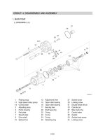
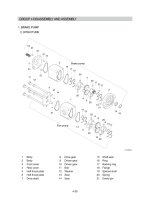
1. MAIN PUMP1. MAIN PUMP
STEERING STEERING (1/2)
1)1)
GROUP 4 DISASSEMBLY AND ASSEMBLYGROUP 4 DISASSEMBLY AND ASSEMBLY
1 Rotary group
1-1 High speed rotary group
1-2 Control plate
2 Adjusting piece
5 Pump housing
6 Port plate
7 Swash plate
8 Drive shaft
10 Splined hub
12 Adjustment shim
15 Taper roller bearing
16 Taper roller bearing
17 Bearing liner
20 Shaft seal ring
22 O-ring
23 O-ring
24 O-ring
25 Retaining ring
27 Socket screw
30 Locking screw
31 Double break-off pin
33 Cylinder pin
37 Side mark ring
51 Control valve
52 Gasket
53 Socket head screw
54 Locking screw
23
27
5
24
10
6,31
16
12
33
52
51
8
15
20
25
22
30
17
7
1-1
1-2
2
54
53
37
76096WE11
6-69
LOADER LOADER (2/2)
23
27
5
2
6,31
16
12
33
2
44
42
8
15
20
25
22
30
17
7
41
11
28
1-2
1-1
43
76096WE12
1 Rotary group
1-1 High speed rotary group
1-2 Control plate
2 Adjusting piece
5 Pump housing
6 Port plate
7 Swash plate
8 Drive shaft
11 Adjustment shim
12 Adjustment shim
15 Taper roller bearing
16 Taper roller bearing
17 Bearing liner
18 Shaft seal ring
22 O-ring
23 O-ring
25 Retaining ring
27 Socket screw
28 Locking screw
30 Locking screw
31 Double break-off pin
33 Cylinder pin
41 Control valve
42 Gasket
43 Socket screw
44 Locking screw
6-70
GENERAL REPAIR GUIDELINESGENERAL REPAIR GUIDELINES
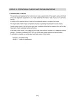
Observe the following guidelines when
carrying out repairs on hydraulic pumps.
Close off all openings of the hydraulic unit.
Replace all of the seals.
Use only original spare parts.
Check all sealing and sliding surfaces for
wear.
Re-work of the sliding surfaces by using,
for example abrasive paper, can damage
the surface.
Fill the hydraulic pump with hydraulic oil
before commissioning.
Change the shaft seal and check its
sliding surface (drive shaft) and housing,
grease the sealing ring.
(2)
2)2)
※
(1)
(2)
(3)
※
(4)
2
1
75796WE60
Assemble the sealing ring, fitting tool
holds the correct position of the sealing
ring in the pump housing.
Assemble the circlip in the correct
position.
(3)
75796WE58
SEALING THE DRIVE SHAFTSEALING THE DRIVE SHAFT
Protect the drive shaft.
Remove the circlip.
Remove the shaft seal.
1 Circlip 2 Shaft seal
3)3)
(1)
75796WE59
6-71
A
A
1
75796WE62
SEALINGSEALING
/
CLEANING THE CONTROL CLEANING THE CONTROL
VALVEVALVE
Disassemble the control valve.
Measure dimension A and note down.
Check sealing surface (1).
4)4)
(1)
※
Mark the location of the connection plate
on the housing.
(2)
75796WE64
75796WE63
DISASSEMBLE THE PUMPDISASSEMBLE THE PUMP
Remove the control valve.
5)5)
(1)
6-72
Remove the connection plate fixing bolts
and the connection plate.
Distributor plate and adjustment piston
can drop down.
(3)
※
75796WE65
Remove distributor plate.
Take note of the orientation.
Remove bearing with withdrawal tool.
Do not damage the sealing surface.
(4)
※
75796WE66
Remove the rotary group in a horizontal
position.
(5)
75796WE67
6-73
Remove swash plate and bearing shells.
(6)
75796WE68
Remove the circlip and the shaft seal.
(7)
75796WE69
Remove the drive shaft through rear side.
(8)
75796WE70
Pre-tension the spring (1) using a suitable
device.
Remove circlip (2).
Remove spring (1) and pressure pins (3).
(9)
1
2
3
75796WE72
6-74
Use bearing puller to remove outer
bearing race of front bearing out of
housing press seat.
(10)
75796WE74
Remove the control plate.
(11)
75796WE75
Use bearing puller to remove outer
bearing race of rear bearing - press seat.
(12)
75796WE76
Disassemble the guide of control piston
(Mounting position: pilot valve side).
(13)
75796WE77
6-75
Disassemble the guide of the opposite
piston.
(14)
75796WE78
75796WE79
INSPECT HINTSINSPECT HINTS
Renew all bearings.
6)6)
(1)
1
2
3
4
5
6
75796WE80
Check :
1 Wear on splines, rust
2 Drive shaft seal wear grooves
3 Bearing seat
4 Splines for cylinder drive
5 Bearing seat
(2)
Check :
Sliding surface free of grooves.
(3)
75796WE81
1
6-76
Check :
Bearing surfaces.
(4)
75796WE82
Check :
Check to see that there are no scratches
or metal deposits on the sliding surface
(1) and that there is no axial play (2)
(Pistons must only be replaced as a set).
(6)
75796WE83
Check :
That the retaining plate is free of grooves
and that there is no wear in the slipper
pad area.
(5)
1
2
2
75796WE84
Check :
1 Cylinder bores
2 Splines
(7)
1
2
75796WE85