Máy xúc lất HuynDai HL760 - P3
Bạn đang xem bản rút gọn của tài liệu. Xem và tải ngay bản đầy đủ của tài liệu tại đây (423.56 KB, 15 trang )
6-53
1. HYDRAULIC OIL CLEAN UP PROCEDURE USING PORTABLE FILTER CADDY1. HYDRAULIC OIL CLEAN UP PROCEDURE USING PORTABLE FILTER CADDY
Service equipment and tool
·
Portable filter caddy
·
Two 4000
mm
× 1in 100R1 Hoses
·
Quick disconnect fittings.
·
Discharge wand
·
Various size fittings.
Brake system uses oil from hydraulic oil
tank. Flush all lines in the brake, pilot,
steering system and cut off system.
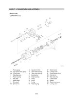
Disassemble and clean major
components for brake and steering
system. Remove and clean pilot caps
from main control valve.
Brake and steering components may fail
if brake and steering system is not
cleaned after hydraulic oil tank
contamination.
If hydraulic system is contaminated due to
a major component failure, remove and
disassemble steering cylinders to clean
debris from cylinders.
Install a new return filter element. Inspect
filter housing before installing new element.
For a failure that creates a lot of debris,
remove access cover from hydraulic oil
tank. Drain and clean hydraulic oil tank of
fill the specified oil to hydraulic oil tank
through upper cover.
To minimize oil loss, pull a vacuum in
hydraulic oil tank using a vacuum pump.
Connect filter caddy suction line to drain
port at bottom of hydraulic oil tank using
connector. Check to be sure debris has not
closed drain port.
Put filter caddy discharge line into hydraulic
oil tank filler hole so end is as far away from
drain port as possible to obtain a thorough
cleaning of oil.
※
※
1)
2)
※
3)
4)
GROUP 3 TESTS AND ADJUSTMENTSGROUP 3 TESTS AND ADJUSTMENTS
6-54
Start the filter caddy. Check to be sure oil is
flowing through the filters.
Operate filter caddy approximately 10
minutes so oil in hydraulic oil tank is
circulated through filter a minimum of four
times.
Hydraulic oil tank capacity : 178
ℓ
(47
U.S.
gal
)
Leave filter caddy operation for the next
steps.
Start the engine and run it at high idle.
For the most effective results, cleaning
procedure must start with the smallest
capacity circuit then proceed to the next
largest capacity circuit.
Operate all functions, one at a time,
through a complete cycle in the following
order: Clam, steering, bucket, and boom.
Also include all auxiliary hydraulic functions.
Repeat procedure until the total system
capacity has circulated through filter caddy
seven times, approximately 30 minutes.
Each function must go through a minimum
of three complete cycles for a through
cleaning for oil.
Filtering time for machines with auxiliary
hydraulic functions must be increased
because system capacity is larger.
Stop the engine. Remove the filter caddy.
Install a new return filter element.
Check oil level in reservoir; Add oil if
necessary.
5)
※
6)
※
7)
※
8)
9)
10)
6-55
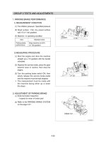
2. BOOM HEIGHT KICKOUT ADJUSTMENT2. BOOM HEIGHT KICKOUT ADJUSTMENT
The bucket can be adjusted to a height
desired by using the boom kick-out device.
Park the machine on level ground and Park the machine on level ground and
blo ck th e ti res to pr event s ud den block the tires to prevent sudden
movement of the machine.movement of the machine.
Press the parking brake switch.Press the parking brake switch.
Fix the front and rear frames by using the Fix the front and rear frames by using the
safety lock bar.safety lock bar.
Do not wor k un der ne ath t he wor k Do not work underneath the work
equipment.equipment.
Top
Bottom
Boom kickout & bucket leveler
set switch
Neutral
Detent
position
ADJUSTMENT OF THE BOOM KICKOUTADJUSTMENT OF THE BOOM KICKOUT
Lift kickout positionLift kickout position
To set the lift kickout, raise the bucket to the
desired position above the midway point. Then
depress the top of switch for 2~3 seconds. The
boom will return to the programmed position
when the raise detent is activated and the boom
is below the kickout position.
Lower kickout positionLower kickout position
To set the lower kickout, lower the bucket to the
desired position below the midway point. Then
depress the top of switch for 2~3 seconds. The
boom will return to the programmed position
when the float detent is activated and the boom
is at least a foot above the kickout position.
Bucket leveler positionBucket leveler position
To set the bucket leveler, roll back the bucket to
the desired position. Then depress the bottom of
switch for 2~3 seconds. The bucket will return to
the programmed position when the roll back
detent is activated and the bucket is below the
leveler position.
1)1)
(1)(1)
(2(2)
(3(3)
75794OP28
6-56
3. TEST TOOLS3. TEST TOOLS
CLAMP-ON ELECTRONIC TACHOMETERCLAMP-ON ELECTRONIC TACHOMETER
INSTALLATIONINSTALLATION
·
Service equipment and tools
Tachometer
A : Clamp on tachometer.
Remove paint using emery cloth and
connect to a straight section of injection
line within 100 mm (4 in) of pump. Finger
Tighten only-do not over tighten.
B : Black clip (
- ). Connect to main frame.
C : Red clip (+). Connect to transducer.
D : Tachometer readout. Install cable.
A
C
B
D
C
B
A
DIGITAL THERMOMETER INSTALLATIONDIGITAL THERMOMETER INSTALLATION
·
Service equipment and tools
Digital thermometer
A : Temperature probe.
Fasten to a bare metal line using a tie
band. Wrap with shop towel.
B : Cable.
C : Digital thermometer.
DISPLAY MONITOR TACHOMETERDISPLAY MONITOR TACHOMETER
The display monitor tachometer is accurate
enough for test work.
1)
2)2)
3)3)
75795SE32
75795SE33
75795SE35
6-57
4. HYDRAULIC OIL WARM UP PROCEDURE4. HYDRAULIC OIL WARM UP PROCEDURE
Install temperature reader (see temperature
reader installation procedure in this group).
Run engine at high idle.
Hold a hydraulic function over relief to heat
the oil.
Periodically cycle all hydraulic functions to
distribute warm oil.
Heat oil to test specification (approx. 45
˚
C).
1)
2)
3)
4)
5)
AA
B
Ride control valve
Ride control system (option)Ride control system (option)
AttentionAttention
Before carrying out any maintenance work
the accumulators must be unloaded (zero
pressure).
For this, unscrew the plug (A) then rotate the
drain screw (B), located under the plug (A), 2
turns anti-clockwise with 3
mm
L-wrench.
The lifting system must firstly be secured
against lowering.
After carrying out maintenance work, screw
the plug (A) and drain screw (B).
·
Tightening torque
A : 0.51
kgf·m
(3.69
lbf·ft
)
B : 0.36
kgf·m
(2.58
lbf·ft
)
※
1)
2)
3)
4)
75796WE28
6-58
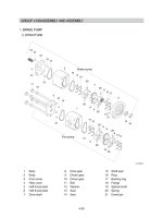
5. MAIN HYDRAULIC PUMP FLOW TEST5. MAIN HYDRAULIC PUMP FLOW TEST
SPECIFICATIONSPECIFICATION
Oil temperature 45
±
5
˚
C (113
±
9˚
F)
Engine speed 2100
±
25
rpm
Test pressure 200
±
5 bar (2900
psi
)
Maximum pump flow 233ℓ/
min
(61.5
gpm
)
FLOW METER GAUGE AND TOOLFLOW METER GAUGE AND TOOL
Gauge 0~35
MPa
(0~350
bar
, 0~5000
psi
)
Temperature reader
Make test connections.
Install temperature reader.
(see temperature reader installation
procedure in this group)
Heat hydraulic oil to specifications.
(see hydraulic oil warm up procedure in this
group)
Run engine at test specifications.
Close flow meter loading valve to increase
pressure to test specifications.
Read flow meter.
If flow is below specifications, check suction
line and suction pressure for abnormality
before removing pump.
·
·
1)
2)
3)
4)
5)
6)
7)
Hyd
tank
MCV
Main pump
B2
Flow meter
P
76096WE29