Máy xúc lất HuynDai HL760 - P1
Bạn đang xem bản rút gọn của tài liệu. Xem và tải ngay bản đầy đủ của tài liệu tại đây (4.45 MB, 42 trang )
SECTION 6 WORK EQUIPMENTSECTION 6 WORK EQUIPMENT
Group 1 Structure and Function
-----------------------------------------------------------------------------------
6-1
Group 2 Operational Checks and Troubleshooting
-----------------------------------------------------
6-42
Group 3 Tests and Adjustments
-----------------------------------------------------------------------------------
6-53
Group 4 Disassembly and Assembly
---------------------------------------------------------------------------
6-68
6-1
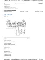
1. HYDRAULIC SYSTEM OUTLINE1. HYDRAULIC SYSTEM OUTLINE
The loader hydraulic system is a pilot operated, closed center system which is supplied with flow
from the variable displacement piston main hydraulic pump.
The loader system components are :
·
Main pump
·
Main control valve
·
Bucket cylinder
·
Boom cylinders
·
Remote control valve (Pilot control valve)
·
Safety valve
Flow from the main hydraulic pump not used by the steering system leaves the steering valve
(EHPS) EF port.
It flows to the inlet port plate of two section or three section block type main control valve.
The main control valve is load pressure independent flow distribution system which routes flow to the
boom, bucket or auxiliary cylinders (not shown) when the respective spools are shifted.
Flow from the main pump is routed to the main control valve where pump outlet pressure is reduced
to pilot circuit pressure. The main control valve flow to the remote control valve.
The remote control valve routed flow to either end of each spool valve section in the main control
valve to control spool stroke.
A accumulator mounted on safety valve supplies a secondary pressure source to operated remote
control valve so the boom can be lowered if the engine is off.
The return circuit for the main hydraulic system have return filter inside the hydraulic tank. The return
filter uses a filter element and a bypass valve. The bypass valve is located in the upside of filter.
SECTION 6 WORK EQUIPMENTSECTION 6 WORK EQUIPMENT
GROUP 1 STRUCTURE AND FUNCTIONGROUP 1 STRUCTURE AND FUNCTION
6-2
2. HYDRAULIC CIRCUIT2. HYDRAULIC CIRCUIT
PS
31
33
32
5
7'
14
22
21
23
24
26
2
27
30
18
18
16
17
16
15
20
35
36
19
1
11
10
4
38
37
6
8
9
39
25
34
28
28
FRONT
REAR
RH
LH
MX
B
T
X1
A
E/G
E/G
PARKING
CL
CR
L
EF
R
P
LS
T
Ps
Ts
ELECTRONICS
1 3
2 4
A
B
DR
A
B
DR
P
T
L
R
S
P
P1
M
T
M
B2
L3
L4
B1
L1
L2
S1
S2
X1
X2
X1 X2
X3
S1
B1
A1
B2
A2
A3
T1
T
P
PS1
B
PS
T
P
L
M
P
T
A
B
P1
T1
P2
T2
A1
A2
B.D/F
B.U
CRAWD
DUMP
1
3
4
2
P
T
1.1
2.1
PS
T
A1
P1
1
2
3
T/M
PS
29
PS
AXLE
13
TP A1
12
RH
LH
B1a1
a2
A2 B2
pst
LS
a3
B3A3
S1
S2
b3
B2A2
b2
29
29
12
b1
PS
PS
Dump
Roll back
Up
Down
Floating
Bucket
Boom
Aux
3
7
1 Main pump
2 Fan & brake pump
3 Main control valve
4 Remote control valve
5 Steering unit
6
Cushion valve
7 Steering valve (EHPS)
7'
Electric steering valve (opt)
8 Controller (opt)
9 Joystick (opt)
10 Safety valve
11 Shuttle valve
12 Boom cylinder
13 Bucket cylinder
14 Steering cylinder
15 Cut-off valve
16 Accumulator
17 Accumulator
18 Pressure sensor
19 Brake valve
20 Pressure switch
21 Hydraulic tank
22 Air breather
23 Return filter
24 By pass valve
25 Strainer
26 Oil cooler
27 Pressure filter
28 Check valve
29 Pressure sensor
30 Fan motor
31 Pump motor (opt)
32 Check block (opt)
33 Pressure sensor (opt)
34 Check valve (opt)
35 Ride control valve (opt)
36 Accumulator (opt)
37
Quick coupler cylinder (opt)
38 Solenoid valve (opt)
39 Stop valve (opt)
76096WE01
6-3
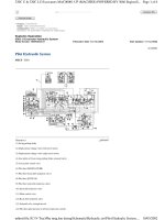
3. WORK EQUIPMENT HYDRAULIC CIRCUIT3. WORK EQUIPMENT HYDRAULIC CIRCUIT
22
21
23
24
1
11
10
4
25
28
28
E/G
B2
L3
L4
B1
L1
L2
S1
S2
X1
X2
X1 X2
X3
S1
B.D/F
B.U
CRAWD
DUMP
1
3
4
2
P
T
1.1
2.1
T
A1
P1
1
2
3
PS
13
TP A1
12
RH
LH
B1a1
a2
A2 B2
pst
LS
a3
B3A3
S1
S2
b3
B2A2
b2
29
12
b1
PS
Dump
Roll back
Up
Down
Floating
Bucket
Boom
Aux
Return line
Fan & brake pump
Steering system
Return line
Steering valve
(EHPS) EF port
Steering valve
(EHPS) LS port
3
PS
29
1 Main pump
3 Main control valve
4 Remote control valve
10 Safety valve
11 Shuttle valve
12 Boom cylinder
13 Bucket cylinder
21 Hydraulic tank
22 Air breather
23 Return filter
24 Bypass valve
25 Strainer
28 Check valve
29 Pressure sensor
76096WE02
6-4
WHEN THE RCV LEVER IS IN THE RAISE POSITIONWHEN THE RCV LEVER IS IN THE RAISE POSITION
When the RCV lever (4) is pulled back, the boom spool is moved to raise position by pilot oil
pressure from port 3 of RCV.
The oil from main pump (1) flows into main control valve (3) and then goes to the large chamber of
boom cylinder (12).
The oil from the small chamber of boom cylinder (12) returns to hydraulic oil tank (21) through the
boom spool at the same time.
When this happens, the boom goes up.
·
·
·
·
22
21
23
24
1
11
10
4
25
28
28
E/G
B2
L3
L4
B1
L1
L2
S1
S2
X1
X2
X1 X2
X3
S1
B.D/F
B.U
CRAWD
DUMP
1
3
4
2
P
T
1.1
2.1
T
A1
P1
1
2
3
PS
13
TP A1
12
RH
LH
B1a1
a2
A2 B2
pst
LS
a3
B3A3
S1
S2
b3
B2A2
b2
29
12
b1
PS
Dump
Roll back
Up
Down
Floating
Bucket
Boom
Aux
Return line
Fan & brake pump
Steering system
Return line
Steering valve
(EHPS) EF port
Steering valve
(EHPS) LS port
3
PS
29
1)1)
76096WE03
6-5
WHEN THE RCV LEVER IS IN THE LOWER POSITIONWHEN THE RCV LEVER IS IN THE LOWER POSITION
When the RCV lever (4) is pushed forward, the boom spool is moved to lower position by pilot
pressure.
The oil from main pump (1) flows into main control valve (3) and then goes to small chamber of
boom cylinder (12).
The oil returned from large chamber of boom cylinder (12) returns to hydraulic tank (21) through
the boom spool at the same time.
When the lowering speed of boom is faster, the return oil from the large chamber of boom cylinder
combines with the oil from the pump through the regeneration check valve, and flows into the small
chamber of the cylinder.
This prevents cylinder cavitation by the negative pressure when the pump flow cannot match the
boom down speed.
·
·
·
·
22
21
23
24
1
11
10
4
25
28
28
E/G
B2
L3
L4
B1
L1
L2
S1
S2
X1
X2
X1 X2
X3
S1
B.D/F
B.U
CRAWD
DUMP
1
3
4
2
P
T
1.1
2.1
T
A1
P1
1
2
3
PS
13
TP A1
12
RH
LH
B1a1
a2
A2 B2
pst
LS
a3
B3A3
S1
S2
b3
B2A2
b2
29
12
b1
PS
Dump
Roll back
Up
Down
Floating
Bucket
Boom
Aux
Return line
Fan & brake pump
Steering system
Return line
Steering valve
(EHPS) EF port
Steering valve
(EHPS) LS port
3
Regeneration
check valve
PS
29
2)2)
76096WE04
6-6
WHEN THE RCV LEVER IS IN THE FLOAT POSITIONWHEN THE RCV LEVER IS IN THE FLOAT POSITION
When the RCV lever (4) is pushed further forward from the lower position, the pilot pressure
reaches to 13~15bar, then the boom spool is moved to floating position.
The work ports (A2), (B2) and the small chamber and the large chamber are connected to the
return passage, so the boom will be lowered due to it's own weight.
In this condition, when the bucket is in contact with the ground, it can be move up and down in
accordance with the shape of the ground.
·
·
·
22
21
23
24
1
11
10
4
25
28
28
E/G
B2
L3
L4
B1
L1
L2
S1
S2
X1
X2
X1 X2
X3
S1
B.D/F
B.U
CRAWD
DUMP
1
3
4
2
P
T
1.1
2.1
T
A1
P1
1
2
3
PS
13
TP A1
12
RH
LH
B1a1
a2
A2 B2
pst
LS
a3
B3A3
S1
S2
b3
B2A2
b2
29
12
b1
PS
Dump
Roll back
Up
Down
Floating
Bucket
Boom
Aux
Return line
Fan & brake pump
Steering system
Return line
Steering valve
(EHPS) EF port
Steering valve
(EHPS) LS port
3
PS
29
3)3)
76096WE05
6-7
WHEN THE RCV LEVER IS IN THE DUMP POSITIONWHEN THE RCV LEVER IS IN THE DUMP POSITION
If the RCV lever (4) is pushed right, the bucket spool is moved to dump position by pilot oil pressure
from port 2 of RCV.
The oil from main pump (1) flows into main control valve (3) and then goes to the small chamber of
bucket cylinder (13).
The oil at the large chamber of bucket cylinder (13) returns to hydraulic tank (21).
When this happens, the bucket is dumped.
When the dumping speed of bucket is faster, the oil returned from the large chamber of bucket
cylinder combines with the oil from the pump, and flows into the small chamber of the cylinder.
This prevents cylinder cavitation by the negative pressure when the pump flow cannot match the
bucket dump speed.
·
·
·
·
·
22
21
23
24
1
11
10
4
25
28
28
E/G
B2
L3
L4
B1
L1
L2
S1
S2
X1
X2
X1 X2
X3
S1
B.D/F
B.U
CRAWD
DUMP
1
3
4
2
P
T
1.1
2.1
T
A1
P1
1
2
3
PS
13
TP A1
12
RH
LH
B1a1
a2
A2 B2
pst
LS
a3
B3A3
S1
S2
b3
B2A2
b2
29
12
b1
PS
Dump
Roll back
Up
Down
Floating
Bucket
Boom
Aux
Return line
Fan & brake pump
Steering system
Return line
Steering valve
(EHPS) EF port
Steering valve
(EHPS) LS port
3
PS
29
Regeneration
check valve
4)4)
76096WE06
6-8
WHEN THE RCV LEVER IS IN THE ROLL BACK WHEN THE RCV LEVER IS IN THE ROLL BACK (retract) POSITION POSITION
If the RCV lever (4) is pulled left, the bucket spool is moved to roll back position by pilot oil pressure
from port 4 of RCV.
The oil from main pump (1) flows into main control valve (3) and then goes to the large chamber of
bucket cylinder.
The oil at the chamber of bucket cylinder (13) returns to hydraulic tank (21).
When this happens, the bucket roll back.
·
·
·
·
22
21
23
24
1
11
10
4
25
28
28
E/G
B2
L3
L4
B1
L1
L2
S1
S2
X1
X2
X1 X2
X3
S1
B.D/F
B.U
CRAWD
DUMP
1
3
4
2
P
T
1.1
2.1
T
A1
P1
1
2
3
PS
13
TP A1
12
RH
LH
B1a1
a2
A2 B2
pst
LS
a3
B3A3
S1
S2
b3
B2A2
b2
29
12
b1
PS
Dump
Roll back
Up
Down
Floating
Bucket
Boom
Aux
Return line
Fan & brake pump
Steering system
Return line
Steering valve
(EHPS) EF port
Steering valve
(EHPS) LS port
3
PS
29
5)5)
76096WE07
6-9
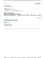
3. MAIN PUMP 3. MAIN PUMP
STRUCTURE STRUCTURE (1/2)
This variable displacement piston pump consists of steering pump and loader pump.
1)1)
L1
L2
B1X1 L3 B2X2
S1 L4 S2
E/G
B2
L3
L4
B1
L1
L2
S1
S2
X1
X2
Hydraulic circuit
76096WE88
Port Port name Port size
B1 Pressure port SAE 1"
B2 Pressure port SAE 1"
S1 Suction port SAE 2"
S2 Suction port SAE 2"
L1, L2 Case drain port 1 1/16-12UN-2B
L3, L4 Case drain port 1 1/16-12UN-2B
X1, X2 Pilot pressure port 7/16-20UNF-2B
6-10
MAIN PUMP MAIN PUMP (1/2, STEERING)
·
1 Rotary group
1-1 High speed rotary group
1-2 Control plate
2 Adjusting piece
5 Pump housing
6 Port plate
7 Swash plate
8 Drive shaft
10 Splined hub
12 Adjustment shim
15 Taper roller bearing
16 Taper roller bearing
17 Bearing liner
20 Shaft seal ring
22 O-ring
23 O-ring
24 O-ring
25 Retaining ring
27 Socket screw
30 Locking screw
31 Double break-off pin
33 Cylinder pin
37 Side mark ring
51 Control valve
52 Gasket
53 Socket head screw
54 Locking screw
23
27
5
24
10
6,31
16
12
33
52
51
8
15
20
25
22
30
17
7
1-1
1-2
2
54
53
37
76096WE11
6-11
MAIN PUMP MAIN PUMP (2/2, LOADER)
·
23
27
5
2
6,31
16
12
33
2
44
42
8
15
20
25
22
30
17
7
41
11
28
1-2
1-1
43
76096WE12
1 Rotary group
1-1 High speed rotary group
1-2 Control plate
2 Adjusting piece
5 Pump housing
6 Port plate
7 Swash plate
8 Drive shaft
11 Adjustment shim
12 Adjustment shim
15 Taper roller bearing
16 Taper roller bearing
17 Bearing liner
20 Shaft seal ring
22 O-ring
23 O-ring
25 Retaining ring
27 Socket screw
28 Locking screw
30 Locking screw
31 Double break-off pin
33 Cylinder pin
41 Control valve
42 Gasket
43 Socket screw
44 Locking screw
6-12
FUNCTIONFUNCTION
2)2)
12345 6
8 9 10
11
7
13 12
L1
X
B
S
L
LS pressure
X
4
10
12 13
75796WE33
1 Drive shaft
2 Swash plate
3 Shoe plate
4 Counter piston
5 Piston
6 Counter spring
7
Pressure & flow compensator
valve
8 Piston shoe
9 Cylinder
10 Control piston
11 Control plate
12
Pressure compensator spool
13 Flow compensator spool
The steering pump and loader pump are variable displacement piston pump. The steering pump
and loader pump are flow controlled by LS signal. When the steering and loader are not being
used, the pumps are at low pressure standby.
The load sensing pressure that is sensed from steering and loader hydraulic systems flows to flow
compensator spool (13). This spool keeps the pump output at a level that is necessary to fulfill the
requirements for the system flow and for the pressure.
The pressure compensator spool (12) also limits maximum system pressure. The pressure
compensator spool (12) prevents damage to the steering and loader hydraulic components from
excessive pressure.
The swivel angle of the pumps is controlled by counter piston (4) and control piston (10). Counter
spring (6) cause swash plate (2) to move at maximum displacement or causes swash plate (2) to
upstroke.
Control piston (10) has a larger area (diameter) than counter piston (4). Control piston (10) causes
swash plate (2) to destroke the pump.
Flow compensator spool (13) and/or pressure compensator spool (12) changes pump output by
regulating the pump discharge pressure that is acting on control piston (10).
6-13
Control piston (10) diameter is larger than counter piston (4) diameter, the oil pressure that is
acting against control piston (10) overcomes the force of counter spring (6). The oil pressure than
causes the pump to destoke.
Pressure and flow compensator valve (7) also controls the maximum output of pump pressure.
When steering and loader pressure rises above pressure compensator setting, pressure
compensator spool (12) overrides flow compensator spool (13). This causes the pump to destroke.
6-14
1
2
4
6
10
21
20 12
L1
X
B
S
L
LS pressure
14
15
22
16
17 18 231319
LS pressure oil
System pressure oil
Return oil
104
12 13
75796WE35
1 Drive shaft
2 Swash plate
4 Counter piston
6 Counter spring
10 Control piston
12
Pressure compensator spool
13 Flow compensator spool
14 Case drain
15 Passage
16 Passage
17 Spring
18 Spring
19
LS line from the metering pump
20 Cavity
21 Passage
22 Passage
23 Cavity
Upstroking of the pump occurs as flow demand from loader and steering system.
The increased flow demand causes a LS pressure in LS line (19). The LS pressure in LS line (19)
combines with the force of spring (18) in cavity (20).
The force of spring (18) causes pump pressure to be higher than the LS pressure (19).
If the combination of LS pressure and of spring force is greater than the pump discharge pressure,
this difference pressure causes spool (13) to move right. As spool (13) moves right, the spool (13)
blocks the flow of supply oil to control piston (10). Pump swash plate (2) is controlled by pressure
and flow as much as hydraulic system requests.
When the oil flow to control piston (10) is blocked, the pilot oil in passage (22) drains to passage
(23). The oil then flows past pressure compensator spool (12) and through passage (16) into the
housing and via the drain line (14) to tank.
Supply oil flows through passage (15) to counter piston (4). The oil acts against counter piston (4).
The oil combines with the force of counter spring (6). This causes swash plate (2) to upstroke.
This also causes the pump flow to increase. As flow requirements are satisfied, the pump output
pressure increase. The pressure increases until the pressure in passage (15) moves flow
compensator spool (13) up to be satisfied with system requirement for pressure and flow.
·Pump discharge pressure = force of spring (18) + LS pressure (19)
UpstrokingUpstroking
(1)(1)
6-15
L1
X
B
S
L
LS pressure
1
2
4
6
10
21
20 12
14
15
22
16
17 18 2313
LS pressure oil
System pressure oil
Return oil
19
104
12 13
75796WE34
1 Drive shaft
2 Swash plate
4 Counter piston
6 Counter spring
10 Control piston
12
Pressure compensator spool
13 Flow compensator spool
14 Case drain
15 Passage
16 Passage
17 Spring
18 Spring
19
LS line from the metering pump
20 Cavity
21 Passage
22 Passage
23 Cavity
The decreased flow demand causes a LS pressure in line (19). The LS pressure in line (19)
combines with the force of spring (18) in cavity (20).
This combination of LS pressure and of spring force is less than the pump pressure in passage
(21). This causes flow compensator spool (13) to move left.
Pump oil now flows through passage (15). The oil then flows past flow compensator spool (13),
through passage (22), and then to control piston (10).
The pump pressure behind control piston (10) is now greater than the combined force of counter
piston(4) and of counter spring (6). The angle of swash plate (2) decreases.
This decreases the pump output and the system pressure.
When the lower flow requirements are met, flow compensator spool (13) moves right up to the
balanced position. Swash plate (2) maintains an angle that is sufficient to provide the lower
required pressure. If the operator does not turn the steering wheel and does not move RCV, then
the pump will return to low pressure standby.
※ Control piston → Changes pump displacement ; influenced by controller.
Counter piston → Helps to change pump displacement but no possible to control this piston.
DestrokingDestroking
(2)(2)