Máy xúc lất HuynDai HL760 - P5.4
Bạn đang xem bản rút gọn của tài liệu. Xem và tải ngay bản đầy đủ của tài liệu tại đây (640.18 KB, 30 trang )
5-30
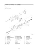
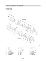
1. STEERING UNIT1. STEERING UNIT
STRUCTURESTRUCTURE
1) 1)
1 Dust seal
2 Housing, spool, sleeve
3 Ball
4 Thread bushing
5 O-ring
7 Bearing assembly
8 Ring
9 Cross pin
11 Cardan shaft
12 Set of springs
13 O-ring
14 Distributor plate
15 Gearwheel set
17 End cover
18 Washer
20 Screw with pin
21 Screw
GROUP 4 DISASSEMBLY AND ASSEMBLYGROUP 4 DISASSEMBLY AND ASSEMBLY
1
5
3
4
2
7
8
9
12
21
20
18
17
13
15
14
13
11
7607SE10
5-31
TOOLSTOOLS
Holding tool + Guide ring
2)2)
(1)
Assembly tool for O-ring and kin-ring.
(2)
Assembly tool for lip seal.
(3)
Assembly tool for cardan shaft.
(4)
(780-3A) 5-69(3)
(780-3A) 5-69(4)
7607SE08
7607SE09
5-32
Assembly tool for dust seal.
(5)
Torque wrench 0~7.1
kgf·m
(0~54.4
lbf·ft
)
13
mm
socket spanner
6, 8
mm
and 12
mm
hexagon sockets
12
mm
screwdriver
2
mm
screwdriver
13
mm
ring spanner
6, 8 and 12
mm
hexagon socket spanners
Plastic hammer
Tweezers
(6)
(780-3A) 5-70(1)
(780-3A) 5-70(2)
5-33
TIGHTENING TORQUE AND HYDRAULIC CONNECTIONSTIGHTENING TORQUE AND HYDRAULIC CONNECTIONS
Hydraulic connectionsHydraulic connections
3)3)
(1)(1)
Tightening torqueTightening torque
(2)(2)
L : Left port
R : Right port
T : Tank
P : Pump
T L P R
(780-3A) 5-71
Screwed
connection
Max. tightening torque [
kgf·m
(
lbf·ft
) ]
With cutting
edge
With copper
washer
With aluminum
washer
With O - ring
1/4 BSP.F 4.1 (29.7) 2.0 (14.5)
3.1 (22.4) -
3/8 BSP.F 6.1 (44.1) 2.0 (14.5)
5.1 (36.9) -
1/2 BSP.F 10.2 (73.8) 3.1 (22.4)
8.2 (59.3) -
7/16-20 UNF - 2.0 (14.5)
--
3/4-16 UNF - 6.1 (44.1)
--
M 12×1.5 4.1 (29.7) 2.0 (14.5)
3.1 (22.4) 2.0 (14.5)
M 18×1.5 7.1 (51.4) 2.0 (14.5)
5.1 (36.9) 5.1 (36.9)
M 22×1.5 10.2 (73.8) 3.1 (22.4)
8.2 (59.3) 7.1 (51.4)
5-34
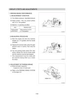
DISASSEMBLYDISASSEMBLY
Disassemble steering column from
steering unit and place the steering unit in
the holding tool.
Screw out the screws in the end cover (6-
off plus one special screw).
4)4)
(1)
Remove the end cover, sideways.
(2)
Lift the gearwheel set (with spacer if
fitted) off the unit.
Take out the two O-rings.
(3)
Remove cardan shaft.
(4)
(780-3A) 5-72(1)
(780-3A) 5-72(2)
(780-3A) 5-72(3)
(780-3A) 5-72(4)
5-35
Remove distributor plate.
(5)
Screw out the threaded bush over the
check valve.
(6)
Remove O-ring.
(7)
Take care to keep the cross pin in the
sleeve and spool horizontal. The pin can
be seen through the open end of the
spool. Press the spool inwards and the
sleeve, ring, bearing races and needle
bearing will be pushed out of the housing
together.
(8)
(780-3A) 5-73(1)
(780-3A) 5-73(2)
(780-3A) 5-73(3)
(780-3A) 5-73(4)
5-36
Take ring, bearing races and needle
bearing from sleeve and spool. The outer
(thin) bearing race can sometimes "stick"
in the housing, therefore check that it has
come out.
(9)
Press out the cross pin. Use the special
screw from the end cover.
(10)
A small mark has been made with a
pumice stone on both spool and sleeve
close to one of the slots for the neutral
position springs (see drawing).
If the mark is not visible, remember to
leave a mark of your own on sleeve and
spool before the neutral position springs
are disassembled.
※
Carefully press the spool out of the sleeve.
(11)
(780-3A) 5-74(1)
(780-3A) 5-74(2)
(780-3A) 5-74(3)
(780-3A) 5-74(4)
5-37
Press the neutral position springs out of
their slots in the spool.
(12)
Remove dust seal and O-ring.
(13)
The steering unit is now completely
disassembled.
(14)
Cleaning
Clean all parts carefully in Shellsol K or
the like.
Inspection and replacement
Replace all seals and washers. Check all
parts carefully and make any
replacements necessary.
Lubrication
Before assembly, lubricate all parts with
hydraulic oil.
※
※
※
(780-3A) 5-75(1)
(780-3A) 5-75(2)
(780-3A) 5-75(3)
5-38
Place the two flat neutral position springs
in the slot.
Place the curved springs between the flat
ones and press them into place.
(1)
Line up the spring set.
(2)
(780-3A) 5-76(4)
Assemble the spool/sleeve and make sure
the marks on spool and sleeve are
opposite each other (see drawing page
5-36).
(3)
(780-3A) 5-76(1)
Press the springs together and push the
neutral position springs into place in the
sleeve.
(4)
(780-3A) 5-77(2)
7607SE06
5-39
Line up the springs and center them.
(5)
Guide the ring down over the sleeve.
The ring should be able to move-free of
the springs.
(6)
※
(780-3A) 5-77(3)
(780-3A) 5-77(4)
Fit the cross pin into the spool / sleeve.
(7)
Fit bearing races and needle bearing.
(See the next page)
(8)
(780-3A) 5-78(1)
(780-3A) 5-78(2)
5-40
Assembly pattern for standard bearings
1 Outer bearing race
2 Needle bearing
3 Inner bearing race
4 Spool
5 Sleeve
The inside chamfer on the inner bearing
race must face the inner spool.
※
*
Installation instruction for O-ring
Turn the steering unit until the bore is
horizontal. Guide the outer part of the
assembly tool into the bore for the spool /
sleeve.
(9)
(780-3A) 5-78(4)
Grease O-ring with hydraulic oil and place
them on the tool.
(10)
(780-3A) 5-79(1)
(780-3A) 5-79(2)
5
4
3
2
1
*
7607SE07
5-41
Hold the outer part of the assembly tool in
the bottom of the steering unit housing
and guide the inner part of the tool right to
the bottom.
(11)
Press and turn the O-ring into position in
the housing.
(12)
(780-3A) 5-79(3)
(780-3A) 5-79(4)
Draw the inner and outer parts of the
assembly tool out of the steering unit
bore, leaving the guide from the inner part
in the bore.
(13)
(780-3A) 5-80(1)
Installation instructions for lip sealInstallation instructions for lip seal
Lubricate the lip seal with hydraulic oil and
place it on the assembly tool.
(14)
(780-3A) 5-80(2)