Máy xúc lất HuynDai HL760 - P4.4
Bạn đang xem bản rút gọn của tài liệu. Xem và tải ngay bản đầy đủ của tài liệu tại đây (431.24 KB, 9 trang )
4-38
GROUP 4 DISASSEMBLY AND ASSEMBLYGROUP 4 DISASSEMBLY AND ASSEMBLY
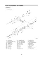
1. BRAKE PUMP1. BRAKE PUMP
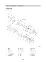
STRUCTURESTRUCTURE
1)1)
1 Body
2 Body
3 Front cover
4 Rear cover
5 Half thrust plate
6 Half thrust plate
7 Drive shaft
8 Drive gear
9 Driven gear
10 Driven gear
11 Bolt
12 Washer
13 Seal
14 Seal
15 Shaft seal
16 Ring
17 Backing ring
18 Flange
19 Splined shaft
20 Spring
21 Dowel pin
16
15
3
7
5
9
20
6
13
17
14
2
21
18
19
21
21
21
14
20
20
20
21
21
17
13
17
13
8
10
20
20
13
14
5
17
1
14
4
12
11
21
21
20
6
20
Fan pump
6
Brake pump
75794BS06
4-39
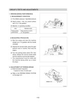
Before disassembling ensure that the unit itself, bench and tools are thoroughly clean.
Lightly mark the flange (18), body (2) and front cover (3) to ensure reassembly in the correct
position.
Remove the bolts (11) and separate the brake pump unit from the fan pump using a soft faced
hammer.
Extract the shaft seal (15) and the ring (16) from the front cover (3).
Remove the front cover (3) from the body (2).
Remove the backing ring (17), the seal (13) and the body seal (14).
Before removing the internal components each bushing (5, 6) must be marked to denote its
location within the body. On the plain area of the bush away from the seal location, lightly mark.
With the unit laying on its side grasp hold of the drive shaft (7) and pull it squarely out of the body
(2) bringing the bushing (5, 6) with it.
Remove the driven gear (9) and the remaining bushing (5, 6).
※
(1)
(2)
(3)
(4)
(5)
※
(6)
(7)
DISASSEMBLYDISASSEMBLY
2)2)
16
15
3
7
5
9
20
6
13
17
14
2
21
18
19
21
21
21
14
20
20
20
21
21
17
13
17
13
8
10
20
20
13
14
5
17
1
14
4
12
11
21
21
20
6
20
Fan pump
Brake pump
75794BS06-1
4-40
INSPECTION AND REPAIRINSPECTION AND REPAIR
AssAssessmentessment
Each components should be thoroughly cleaned, carefully examined and assessed for suitability
re-use. Below is a guide for inspecting the various components.
Bodyody
Inspect the body bore cut-in where both gears wipe into the body.
The body can only be re-used if the
cut-incut-in is bright and polished in appearance and the depth
does not exceed 0.15
mm
(0.006").
The body should be replaced if the surface is scored, has a matt appearance or shows signs
that the tip of the gears have dug in and torn away the surface material.
The body should be inspected to ensure that there is no superficial damage which may
adversely effect performance or sealing. Pay particular attention to the port threads and body
O-ring seal recesses.
Flange Flange and coverand cover
The inner surfaces should be inspected to ensure that there is no unusual wear or scoring in the
regions where the body O-rings and backing rings contact, which result in external leakage.
Check the shaft seal recess for scoring or damage that could result in oil leakage around the
outer diameter of the shaft seal. Replacement shaft seals can be refitted with Loctite hydraulic
sealant to overcome slight damage in this area.
BuBushesshes
The side faces which abut the gears should be perfectly flat showing no sign of scoring.
Characteristically there are bright polished areas on this surface caused by loading against the
gear side faces, which is often more pronounced on the low pressure side. The bush should be
replaced if there is any general scoring or fine scoring with a matt appearance or tearing of the
surface material. Often there is a witness where the tips of the opposing gears have wiped an
overlap reassembling a half moon shape. There must be no noticeable wear step as it is critical
that the bush side face is completely flat to the gear side face.
The bearing liners are acceptable providing that they are not scored or show other damage.
The general outside area of the bush should not show any prominent signs of wear.
GearGears
The gear side faces should be examined for bruising or scoring. Often operation on
contaminated fluid shows scoring between the root of the gear and the journal undercut, which
leaves a wear step. If a wear step can be felt, coincidental with the root diameter, by drawing a
sharp pointed tool across the surface from the undercut outwards towards the tip of the gear,
then the gear is unserviceable.
The gear teeth should then be carefully examined to ensure that there are no signs of bruising or
pitting.
The journal bearing surfaces should be completely free from scoring or bruising. The surface
should appear highly polished and smooth to touch.
Examine the area where the shaft seal lips run on the drive shaft, this shows up as a polished
ring or rings. If a noticeable groove can be felt or there is scoring the shaft should be replaced.
Provided the drive shaft is not damaged from the drive-coupling and the gears have not been
harmed as described above, then the gears can be re-used. If, however, the gears are
damaged they must be replaced as a matched pair.
As a matter of good practice, when pumps have been disassembled, all the seals should be
replaced. It is most important that only the genuine seals are used.
(1)(1)
(2)(2)
(3)(3)
①
②
③
④
①
②
(4)(4)
①
②
(5)(5)
①
②
③
④
⑤
⑥
3)3)
4-41
Ensure that all parts are perfectly clean and lightly lubricate the bushes and gears with hydraulic
oil (ensure body O-ring recess and end faces remain free from oil). This will assist with their
assembly when they are later fitted into the body.
Fit the new seal (13) and backing ring (17) to the bushing (5, 6).
Refit the bushing (5, 6) into the undowelled end of the body (2) from where they were removed.
Place the front cover (3) and new body seal (14) against the body (2) and then stand the
assembly on the cover so that the hollow dowels are uppermost, i.e. the bushing should be at the
bottom with the bushings against the cover.
Fit the drive shaft (7) and driven gear (9) back into their original positions in the body (2).
Refit the plate bushing (5, 6) into their original bores.
Fit the new body seal (14).
Fit the new seal element (13) and backing ring (17) to the bushing.
Carefully refit the flange (18) to the body (2). If the flange (18) is not fitted squarely the seal (14)
may become misplaced and trapped, resulting in internal damage if the unit is run in this
condition.
※
(1)
(2)
(3)
(4)
(5)
(6)
(7)
(8)
ASSEMBLYASSEMBLY
4)4)
16
15
3
7
5
9
20
6
13
17
14
2
21
18
19
21
21
21
14
20
20
20
21
21
17
13
17
13
8
10
20
20
13
14
5
17
1
14
4
12
11
21
21
20
6
20
Fan pump
Brake pump
75794BS06-1
4-42
Fit coupling (19) to the flange (18).
Holding the whole unit together carefully turn it over, making sure it is supported on the flange
(18) not the shaft.
Tighten the bolt (11) with washer (12).
·Tightening torque : 7.1
kgf·m
(51.6
lbf·ft
)
Pour a small amount of oil into a port and check that the shaft can be rotated without undue force
using a smooth jawed hand wrench hooked around the shaft or a suitable half coupling locked
against the key.
(10)
(11)
※
ASSEMBLYASSEMBLY
(9)
16
15
3
7
5
9
20
6
13
17
14
2
21
18
19
21
21
21
14
20
20
20
21
21
17
13
17
13
8
10
20
20
13
14
5
17
1
14
4
12
11
21
21
20
6
20
Fan pump
Brake pump
75794BS06-1