Máy xúc lất HuynDai HL760 - P4.1
Bạn đang xem bản rút gọn của tài liệu. Xem và tải ngay bản đầy đủ của tài liệu tại đây (1.84 MB, 29 trang )
SECTION 4 BRAKE SYSTEMSECTION 4 BRAKE SYSTEM
Group 1 Structure and Function
--------------------------------------------------------------------------------------
4-1
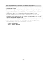
Group 2 Operational Checks and Troubleshooting
--------------------------------------------------------
4-29
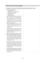
Group 3 Tests and Adjustments
--------------------------------------------------------------------------------------
4-36
Group 4 Disassembly and Assembly
------------------------------------------------------------------------------
4-38
4-1
1. OUTLINE1. OUTLINE
The brakes are operated by a pressure compensated, closed center hydraulic system.
Flow is supplied by a fixed displacement, gear type brake pump.
BRAKE SYSTEMBRAKE SYSTEM
The fixed displacement brake pump supplies flow to the cut-off valve for service brake circuit and
park brake circuits. It flows to three accumulator. The accumulator has a gas precharge and an
inlet check valve to maintain a pressurized volume of oil for reserve brake applications.
Oil through the accumulator flows to the brake valves. The brake valve is a closed center design,
dual circuit operated by a pedal.
The front and rear brakes will operate simultaneously with only one brake pedal depressed.
The differential contains annular brake piston and double sided disk.
Brake pump flow also goes to the parking brake solenoid valve in cut-off valve.
The brake system contains the following components:
·
Brake pump
·
Parking brake solenoid valve in cut-off valve
·
Cut-off valve
·
Brake valve
·
Accumulators
·
Pressure switches
SECTION 4 BRAKE SYSTEMSECTION 4 BRAKE SYSTEM
GROUP 1 STRUCTURE AND FUNCTIONGROUP 1 STRUCTURE AND FUNCTION
※
4-2
FULL POWER HYDRAULIC BRAKE FULL POWER HYDRAULIC BRAKE
SYSTEMSYSTEM
ADVANTAGESADVANTAGES - The full power hydraulic
brake system has several advantages over
traditional brake actuation systems. These
systems are capable of supplying fluid to a
range of very small and large volume
service brakes with actuation that is faster
than air brake systems. Figure represents
a time comparison between a typical air/
hydraulic and full power hydraulic brake
actuation system.
Full power systems can supply significantly
higher brake pressures with relatively low
reactive pedal forces. The reactive pedal
force felt by the operator will be proportional
to the brake line pressure being generated.
This is referred to as brake pressure
modulation.
Another key design feature of full power
systems is the ability to control maximum
brake line pressure. In addition, because
these systems operate with hydraulic oil,
filtration can be utilized to provide long
component life and low maintenance
operation.
Because these systems are closed center,
by using a properly sized accumulator,
emergency power-off braking that is
identical to power-on braking can be
achieved. These systems can be either
dedicated, where the brake system pump
supplies only the demands of the brake
system or non-dedicated, where the pump
supplies the demands of the brake system
as well as some secondary down stream
hydraulic device.
Another important note is that all seals
within these system must be compatible
with the fluid medium being used.
Response timeResponse time
Full power brake actuation VSFull power brake actuation VS
Air/Hydraulic brake actuationAir/Hydraulic brake actuation
Brake torque(lb·in)
1000
900
800
700
600
500
400
300
200
100
Time(seconds)
Brake torque
(Full power)
Brake torque
(Air/hydraulic)
Brake pressure
(Full power)
Brake pressure
(Air/hydraulic)
0 1 2 3 4
4-3
2. HYDRAULIC CIRCUIT2. HYDRAULIC CIRCUIT
22
21
23
24
26
2
27
18
18
16
17
16
15
20
19
25
Front
Rear
E/G
Parking
B1
A1
B2
A2
A3
T1
T
P
PS1
B
PS
P1
T1
P2
T2
A1
A2
T/M
Return line
Main pump
Return line
Fan drive motor
Return line
Return line
PS
PS
39
40
2 Fan & brake pump
15 Cut-off valve
16 Accumulator
17 Accumulator
18 Pressure sensor
19 Brake valve
20 Pressure switch
21 Hydraulic tank
22 Air breather
23 Return filter
24 Bypass valve
25 Strainer
26 Oil cooler
27 Pressure filter
39 Axle
40 Parking brake at T/M
76094BS01
4-4
SERVICE BRAKE RELEASEDSERVICE BRAKE RELEASED
When the pedal of brake valve (19) is released, the operating force is eliminated by the force of the
spring, and the spool is returned.
When the spool removes up, the drain port is opened and the hydraulic oil in the piston of axles
return to the tank (21).
Therefore, the service brake is kept released.
Front
Rear
E/G
Parking
B1
A1
B2
A2
A3
T1
T
P
PS1
B
PS
P1
T1
P2
T2
A1
A2
T/M
Return line
Main pump
Return line
Fan drive motor
Return line
Return line
PS
PS
39
40
22
21
23
24
26
2
27
18
18
16
17
16
15
20
19
25
1)1)
76094BS02
4-5
SERVICE BRAKE OPERATEDSERVICE BRAKE OPERATED
When the pedal of brake valve (19) is depressed, the operating force overcomes the force of the
spring, and is transmitted to the spool. When the spool moves down, the inlet port is opened, and
at the same time the hydraulic oil controlled the pressure level by the cut-off valve (15) enters the
piston in the front and rear axles. Therefore, the service brake is applied.
25
Front
Rear
E/G
Parking
B1
A1
B2
A2
A3
T1
T
P
PS1
B
PS
P1
T1
P2
T2
A1
A2
T/M
Return line
Main pump
Return line
Fan drive motor
Return line
Return line
PS
PS
39
40
22
21
23
24
26
2
27
18
18
16
17
16
15
20
19
25
2)2)
76094BS03
4-6
PARKING BRAKE RELEASEDPARKING BRAKE RELEASED
When the parking brake switch is pressed A position, the solenoid valve is energized and the
hydraulic oil controlled the pressure level by the cut-off valve enters the parking brake. It overcomes
the force of the spring and pushes the piston rod. This releases the brake.
Therefore, the hydraulic oil pressure is applied to the parking brake piston through the solenoid
valve and the parking brake is kept released.
Front
Rear
E/G
Parking
B1
A1
B2
A2
A3
T1
T
P
PS1
B
PS
P1
T1
P2
T2
A1
A2
T/M
Return line
Main pump
Return line
Fan drive motor
Return line
Return line
PS
PS
39
40
Parking brake switch
A
B
P
Parking brake
solenoid
22
21
23
24
26
2
27
18
18
16
17
16
15
20
19
25
3)3)
76094BS04
4-7
PARKING BRAKE OPERATEDPARKING BRAKE OPERATED
When the parking brake switch is pressed B position, the solenoid valve is deenergized and the
valve open the drain port.
At the same time, the hydraulic oil in the parking brake return to the tank through the solenoid
valve. When the piston rod is returned by the force of the spring, the parking brake is applied.
Front
Rear
E/G
Parking
B1
A1
B2
A2
A3
T1
T
P
PS1
B
PS
P1
T1
P2
T2
A1
A2
T/M
Return line
Main pump
Return line
Fan drive motor
Return line
Return line
PS
PS
39
40
Parking brake switch
A
B
P
Parking brake
solenoid
22
21
23
24
26
2
27
18
18
16
17
16
15
20
19
25
4)4)
76094BS05
4-8
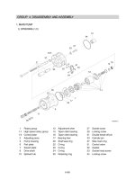
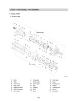
3. BRAKE PUMP 3. BRAKE PUMP (+FAN PUMP)
STRUCTURESTRUCTURE
1)1)
1 Body
2 Body
3 Front cover
4 Rear cover
5 Half thrust plate
6 Half thrust plate
7 Drive shaft
8 Drive gear
9 Driven gear
10 Driven gear
11 Bolt
12 Washer
13 Seal
14 Seal
15 Shaft seal
16 Ring
17 Backing ring
18 Flange
19 Splined shaft
20 Spring
21 Dowel pin
This gear pump have a maximum delivery pressure of 150
kgf/cm
2
.
The pressure loaded type gear pump is designed so that the clearance between the gear and the
bushing can be automatically adjusted according to the delivery pressure. Therefore, the oil leakage
from the bushing is less than that in the case of the fixed bushing type under a high discharge pressure.
Consequently, no significant reduction of the pump delivery occurs, even when the pump is operated
under pressure.
16
15
3
7
5
9
20
6
13
17
14
2
21
18
19
21
21
21
14
20
20
20
21
21
17
13
17
13
8
10
20
20
13
14
5
17
1
14
4
12
11
21
21
20
6
20
Fan pump
6
Brake pump
75794BS06
4-9
PRINCIPLE OF OPERATIONPRINCIPLE OF OPERATION
Mechanism for delivering oilMechanism for delivering oil
The drawing at right shows the
operational principle of an external gear
pump in which two gears are rotating in
mesh.
The oil entering through the suction port
is trapped in the space between two gear
teeth, and is delivered to the discharge
port as the gear rotates.
Except for the oil at the bottom of the gear
teeth, the oil trapped between the gear
teeth, is prevented from returning to the
suction side with the gears in mesh.
Since the gears are constantly delivering
oil, the oil delivered to the discharge port
is forced out of the port.
The amount of discharge increases with
the speed of rotation of the gear.
If there is no resistance in the oil passage
into which the discharged oil flows, the oil
merely flows through the passage,
producing no increase in pressure.
If however, the oil passage is blocked with
something like a hydraulic cylinder, there
will be no other place for the oil to flow, so
the oil pressure will rise. But the
pressure which rises in this way will never
go higher, once the hydraulic cylinder
piston starts moving because of the oil
pressure.
As described earlier, the pump produces
the oil flow, but not the oil pressure. We
can therefore conclude that pressure is a
consequence of load.
In other words, the pressure depends on
a counterpart.
Suction Discharge
(1)(1)
2)2)
(770-3ATM) 4-9
4-10
Internal oil leakageInternal oil leakage
Oil leaks from a place under higher
pressure to a place under lower pressure,
provided that a gap or a clearance exists
in between.
In the gear pump, small clearances are
provided between the gear and the case
and between the gear and the side plate
to allow the oil to leak out and to serve as
a lubricant so that the pump will be
protected from seizure and binding.
The drawing at right shows how the
leaked oil flows in the pump. As such,
there is always oil leakage in the pump
from the discharge side (under higher
pressure) to the suction side. The delivery
of the pump is reduced by an amount
equal to the pump discharge.
In addition, the delivery of the pump will
also decrease as the amount of oil
leakage increases because of expanded
radial clearance resulting from the wear of
pump parts, the lower oil viscosity
resulting from increases in the oil
temperature, and the initial use of low
viscosity oil.
Discharge
(2)(2)
(770-3ATM) 4-10
Suction