Bài giảng thủy lực - Tiếng anh - P5
Bạn đang xem bản rút gọn của tài liệu. Xem và tải ngay bản đầy đủ của tài liệu tại đây (238.76 KB, 5 trang )
A STUDY ON THE CONTROLLABILITY OF FLOW-PRESSURE
RELATIONSHIP OF THE PILOT OPERATED PRESSURE RELIEF VALVE
Wu Wanrong,Qiu Minxiu,Wei Jianhua,Wu Genmao
Institute of Mechatronic Control Engineering, Zhejiang University, and Hangzhou 310027 P.R.China
ABSTRACT
The flow-pressure relationship is an important external
characteristic of the pilot operated pressure relief valve.
Many research efforts have been put on this topic for its
significant impact on the overall hydraulic system.
Some of the researches focused on the influences of the
hydraulic bridge to the main stage, while the others
attempted to analyze the influence of difference pressure
measurement (direct or indirect) of the system pressure
using control theories. In this project, a novel method
has been adopted. The basic idea is to find out the
correlation between the pilot flow and the overflow of
the main valve, and use this relative function as a
criterion to compensate for the force bore on the valve
poppet. The flow-pressure curve of the relief valve can
be bent upwards(under-compensated), flat, or
downwards(over- compensated). The above scheme has
been utilized in the manufacture’s product catalogs.
Key words: variable hydraulic resistance, force
compensating, relief valve, controllability
INTRODUCTION
In pilot operated pressure relief valve, the main valve is
actually controlled by the pilot hydraulic bridge. On the
other hand, the pilot hydraulic circuit and the main
valve port hydraulic circuit form parallel hydraulic
network. The current researches show that the steady-
state override pressure is related to the control pattern of
the pilot valve and varied with where the pressure
exerting on the pilot valve and where the pressure sign
coming from[1]. This paper intends to find the
correlationship between the pilot flow and the main
overflow of the relief valve, and to control the flow-
pressure characteristic of the pilot operated pressure
relief valve by compensating for the force bore on the
pilot poppet according to the correlationship.
THE CORRELATIONSHIP BETWEEN THE
PILOT FLOW AND THE MAIN
OVERFLOW OF THE RELIEF VALVE
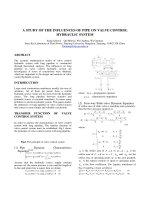
Fig.1 shows the structure and the principle of the relief
valve with compensating for the force bore on the pilot
poppet. And the flow equations and force equilibrium
equations under steady-state are described below.
The related flow equations of the pilot hydraulic circuit
are as follows:
pp
c
q
21
1
1
−= (1)
pp
y
b
q
32
2
2
−= (2)
p
c
q
3
3
3
= (3)
Neglecting the steady-sate hydrodymatic force, the
force equilibrium equation of the pilot poppet:
a
p
a
py
y
k
3
3
2
21
2
)( +=+ (4)
The flow equation of the main valve port:
p
x
b
q
x 1
1
= (5)
the force equilibrium equation of the piston:
p
x
b
A
p
A
p
x
xk
1
02
2
1
1
11
)( −−=+ (6)
Fig. 1 The structure and principle of the relief valve with
compensating for force bore on the pilot poppet
Where 2
11
1
1
ρ
µ
ac
= , 2
13
3
3
ρ
µ
ac
= ;
µ
1
,
µ
3
are
the flow coefficient of orifice r
1
and r
3
respectively,
ρ
is fluid mass density, a
11
and a
13
are the cross-area
of r
1
and r
3
respectively
;
b
1
b
2
the coefficient of the main valve port and
pilot valve port respectively;
b
0
the coefficient of the steady-sate
hydrodymatic force of the main valve port;
A
1
A
2
the effective area of the piston on the
lower end and upper end respectively;
a
2
a
3
the effective area of the different part of
the pilot poppet;
k
1
k
2
spring stiffness
x
1
y
1
the precompression quantity of spring.
The function between q
2
and q
x
can be solved by
formulas (1)~(6), but result is very complex. To
simplify the result, change formulas (1)~(6) into
increment equations. Considering q
1
=q
2
=q
3
, at a steady-
state point(q
20
q
x0
x
0
y
0
) the increments equations
are as follows:
)(
2
21
20
2
1
2
pp
q
c
q
∆−∆=∆ (7)
)(
2
21
20
2
0
2
2
0
20
2
pp
q
y
b
y
y
q
q ∆−∆+∆=∆ (8)
p
q
c
q
3
20
2
3
2
2
∆=∆ (9)
a
p
a
p
y
k
3
3
2
2
2
∆+∆=∆ (10)
p
q
xb
x
x
q
x
q
x
x 1
0
2
0
2
1
0
0
2
∆+∆=∆ (11)
x
xb
q
b
k
p
A
p
xbA
x
∆+=∆−∆− )()(
2
0
2
1
2
0
0
1
2
2
1
00
1
(12)
From equations (7)~(12), the following equation can be
derived.
( )
( )
q
m
q
cAmm
q
q
a
y
bkxcc
q
q
x
x
xx
∆
+
+
=∆
3
2
0
2
1
2
21
20
2
0
2
3
0
2
2
20
2
3
2
1
0
2
2
2
13
Where
ca
q
ca
q
mm
2
1
3
2
20
2
3
2
2
20
41
22 −+= (14)
xbxb
q
A
q
m
xx
3
0
2
1
00
2
0
1
2
0
2
22 +−= (15)
b
y
kc
y
ka
q
m
2
2
2
0
2
2
30
23
2
20
3
2 −−= (16)
)(
2
3
2
1
2
2
2
0
2
2
3
2
1
0
24
ccb
y
kcc
y
km
++= (17)
The first part (m4) in right hand of formula (14) can be
omitted when compared with the others, so do the last
two parts in equations (15) and (16).Therefore, formula
(13) can be rewritten as follows:
Fig.2 The emulation curve of pilot flow varying with
the changing of the main overflow
( )
[ ]
q
acAAcaA
q
a
y
bkxcc
q
x
x
x
∆
−+
+
≈∆
3
2
1
12
2
3
2
1
3
200
2
0
2
3
0
2
2
20
2
3
2
1
2
)(4
2
(18)
Generally, A
A
, and each of parameters in formula
(18) is positive, consequently, the pilot flow increases as
the main overflow increases. The theoretical and
experimental relationship of the pilot flow and the main
overflow are shown in Figs 2-3, from which it can be
seen that they coincide very much. Figs 2-3 also show
that the changing amplitude of the pilot flow follows
with the varying of the main overflow under different
system pressure. It can be proven that the results can
meet all pilot operated pressure relief valve with
different structure.
Fig.3 The experimental curve of the pilot flow
varying with the overflow under different system
pressure
THE COMPENSATING FOR THE
FORCE BORE ON THE PILOT POPPET
The disadvantage of general relief valve is that the
system pressure increases with the increasing of the
overflow, and the higher the system pressure, the
greater the override pressure (Fig.4 shows).
Fig.4 The experimental curve of the override pressure
changing with the overflow under different system
pressure
According to the results above, the override pressure of
the relief valve can be compensated by attaching
hydraulic resistance in the pilot hydraulic circuit. The
compensating method is to connect the pilot poppet with
the compensating piston which consists of an orifice
(Fig.1), when fluid flow through the orifice, cause a
pressure difference in it, thus modifying the equilibrium
2
1
30
25
20
15
10
5
P
1
(Mpa)
q
x
(L/min)
)
q
2
(L/min)
)
200100
0 50 100 150 200
0.0
0.2
0.4
0.6
0.8
1.0
1.2
P
1
=10MPa
P
1
=15MPa
P
1
=20MPa
q
2
(L/min)
q
x
(L/min)
0
P
1
(Mpa)
30
20
10
0
0 100 200
q
x
(L/min)
state of force bearing on the pilot poppet and reducing
the resistance of the variable hydraulic resistance of the
pilot valve port to fluid. This results in compensating
the unfavorable effects to system pressure causing by
the factors of the pilot valve, such as hydrodymatic
force, spring force, etc., when the main overflow varies.
Compensating force F
c
:
a
p
F
c 3
3
= 19
According to equation (2), the hydraulic resistance of
the pilot valve port under a steady-state point is as
follows[2]:
y
b
pp
q
d
pd
R
a
aa
a
a
2
32
2
2 −
=
∆
=
In order to discuss the general hydraulic resistance
property of the pilot valve port, the above equation can
be rewritten:
y
b
pp
R
2
32
2 −
= 20
Transform the formula (19) and (20) into increment
equations:
p
a
F
c
3
3
∆=∆ (21)
y
y
b
q
q
pp
R ∆−
∆−∆
=∆
3
0
2
2
10
20
21
2
(22)
Solve equations (7)~(10) and (22), we can get:
q
y
bka
q
c
aa
q
y
bka
qy
b
y
bka
q
R
2
3
0
2
2
22
2
20
2
3
32
2
20
3
0
2
2
22
2
20
2
0
2
2
2
0
2
2
22
2
20
)
2
(
)(8
)
2
(
24
∆
+
+
+
+
−
−=∆
(23
Where the latter part of the numerator in the first
fraction can be omitted when compared with the former
part, the other parameters in formula (23) are positive,
therefore, the hydraulic resistance of the pilot valve port
decreases with the increasing of the pilot flow. The
second part of the square bracket of the formula (23)
results from the compensating force, which results in
more reducing the hydraulic resistance of the pilot valve
port with the increasing of the pilot flow. The greater
the parameter a
3
or the smaller the parameter c
3
, the
greater the compensating force and the decreasing
amplitude of the pilot valve port hydraulic resistance.
From formulas (9) and (21), get:
q
c
a
q
F
c
2
2
3
3
20
2
∆=∆ 24
Consequently, compensating force increases with the
increasing of the pilot flow. The variation of the
compensating force with the changing of the pilot flow
has something to do with the pilot flow of the steady-
state point and changes with the different structural
parameters a
3
c
3
, Fig.5 shows the theoretical
relationship of the compensating force and the pilot
flow with the different structural parameter c
3.
Fig. 5 The emulation curve of the compensating force
varying with the changing of the pilot flow
THE CONTROLLABILITY OF THE
FLOW-PRESSURE CHARACTERISTIC
OF THE RELIEF VALVE
Because the changing amplitude of the compensating
force with the varying of the pilot flow is mainly
dependent on the structural parameters a
3
and c
3
according to formula (24), it is reasonable to change the
hydraulic resistance property which varies with the
changing of pilot flow. According to the formula
(7)~(10) and (21):
F
p
c
∆=∆ λ
1
25
)2(
2
2)(
3
0
2
0
2
2
20
3
2
1
2
1
3
2
20
2
3
2
2
20
2
3
2
1
3
0
2
2
2
2
3
2
1
0
2
y
bk
q
ac
ca
q
ca
q
cc
y
bkcc
y
k
+
−+
+
+
=λ
26
From formula (25), it can be seen that different
λ
will
results in different characteristic of the control
pressure p
1
varying with the compensating force:
λ >0p
1
increases with the increasing of the
compensating force, this is under-compensated
;
λ
=0p
1
keeps constant, and does not change with
the compensating force, right-compensated;
λ <0p
1
decreases with the increasing of the
compensating force, over-compensated.
Meanwhile, the value of λ is only dependent on the
structural parameters and pilot flow. In formula (26),
the value of denominator is positive, so, whether the
value of λ is positive, zero or negative is decided by
the value of the numerator. The first two parts of the
numerator in the formula (26) can be omitted when
compared with the others, so the value of
λ
is
mainly dependent on the last two parts , i.e.
caca
2
1
3
2
3
2
− >0
λ
>0
caca
2
1
3
2
3
2
− =0 λ =0
caca
2
1
3
2
3
2
− <0
λ
<0
Consequently, the value of
λ
is mainly dependent on
the arrangement of the parameters a
2
, a
3
, c
1
, c
3
, When
the parameters a
2
and c
1
are fixed, the value of
λ
is
decided by a
3
and c
3
. Fig.6 shows the theoretical
relationship of the control pressure varying with the
compensating force under different parameter value
of a
3
(or c
3
), i.e. λ .
0 2 4 6 8 10 12
0
10
20
30
40
0 0.2 0.4 0.6 0.8 1.0 1.2
c
31
<c
32
<c
33
c
33
c
32
c
31
F
c
(N)
q
2
(L/min)
0 5 10 15
16000000
18000000
20000000
22000000
16
22
20
18
p
1
(MPa)
F
c
(N)
2.5233×10
-20
-1.9842×10
-20
-1.4763×10
-21
( a
2
c
3
2
-a
3
c
1
2
)
Fig.6 The emulation curve of the control pressure
varying with the changing of the compensating force
From formulas (24) and (25):
q
c
a
q
p
2
2
3
3
20
1
2
∆⋅=∆ λ 27
According to formulas (18) and (27), it can be seen that
the flow-pressure relationship of the relief valve is also
dependent on the value of
λ
, i.e. there exists different
flow-pressure characteristic of the relief valve with
the different matching of the parameters a
2
, a
3
, c
1
, c
3
:
under-compensated,
λ
>0, the pressure increases with
the increasing of the overflow; right-compensated,
λ
=0the pressure
keeps constant, and does not change with overflow;
over-compensated,
λ
<0the pressure decreases
with the increasing of the overflow.
EXPERIMENT ON FLOW-PRESSURE
CHARACTERISTIC OF THE RELIEF
VALVE
Fig.1 shows the structure of the experimental valve
(NG10), the relational structural parameters are as
follows[3]: d
r1
=0.6mm, a
2
=12.566mm
2
, a
3
=164.15mm
2
,
A
1
=76.2mmm
2
, A
2
=78.54mm
2
. Fig.7 shows the
experimental results of the pressure varying with the
overflow under d
r3
=1.0mm, d
r3
=1.1mm, d
r3
=1.2mm.
d
r3
=1.0mm, the pressure reduces with the increasing
of the overflow in Fig 5c; d
r3
=1.1mm, the pressure
keeps constant, it does not change with the increasing
or decreasing of the overflow in Fig. 5b; d
r3
=1.2mm,
the pressure increases with the increasing of the
overflow in Fig. 5a. There exists different flow -
pressure characteristic of the relief valve with the
different of d
r3
(or
λ
).
Consequently, it is reasonable to obtain the flow-
pressure characteristic required according to the
different parameters of the pilot hydraulic circuit.
Some kinds of pressure valves have been
manufactured by applying the above principle by
Roxroth Ltd. Fig.8 shows one of the products, a pilot
operated pressure relief valve[4].
Fig.8 The structure and principle of the relief valve of
Roxroth Ltd.
CONCLUSIONS
(1) The pilot operated pressure valve is made up of
parallel hydraulic network which formed by the
hydraulic circuit of the pilot valve and that of the main
valve port. The pilot flow increases with the increasing
of the main overflow, and the greater the system
pressure, the more the variation of the pilot flow varying
with the overflow.
(2) The flow-pressure characteristic of the pilot
operated pressure valve can be compensated by
altering the equilibrium state of the force bore on the
pilot poppet through attaching hydraulic resistance in
the pilot poppet.
(3)There exists different flow-pressure characteristic
with different compensating degree of the force bore on
the pilot poppet: under-compensated, the flow-
pressure curve will be bent upwards; right-
compensated, kept flat; over-compensated, bent
downwards.
(4) The principle of compensating the override pressure
of the relief valve by attaching a hydraulic resistance in
the pilot circuit is actually to compensate the variable
hydraulic resistance of the pilot hydraulic bridge, which
is suited for other pressure valves controlled by, for
example, B half bridge.
P
1
(MPa)
20 (a)
0 50 100 150 200
P
1
(MPa) q
x
(L/min)
20 (b)
0 50 100 150 200
P
1
(MPa) q
x
(L/min)
20 (b)
0 50 100 150 200
q
x
(L/min)
Fig.7 The experimental curves of the flow-
pressure characteristic of the relief valve
REFERENCES
[1] Tang Quanbo, Li Zhaomin, Li Zhangyun. The
analysis on the override pressure of relief valve,(in
Chinese). Machine tool and hydraulics. 1989(6):21~23
[2] Backé W, Zhu Wen. Hydraulic resistance circuit
systemology, (in Chinese). Beijing: China
machinery press. 1980
[3] Wu GenmaoVorgesteuertes
Druckbegrenzungsventil DB10 Serie 30
Versuchsbericht V932Mannesmann Rexroth
GmbH1984
[4] Rexroth. Induetrieventile und Zubehör.
RD00101/09.92, ss.165