Bài giảng thủy lực - Tiếng anh - P4
Bạn đang xem bản rút gọn của tài liệu. Xem và tải ngay bản đầy đủ của tài liệu tại đây (61.67 KB, 4 trang )
A STUDY OF THE INFLUENCES OF PIPE ON VALVE CONTROL
HYDRAULIC SYSTEM
Kong XiaowuQiu Minxiu, Wei Jianhua, Wu Genmao
State Key Laboratory of Fluid Power, Zhejiang University, Hangzhou, Zhejiang, 310027,P.R.China
ABSTRACT
The accurate mathematical model of valve control
hydraulic system with long pipeline is constructed
through theoretical analysis. The influences of long
pipeline on valve control hydraulic system are
investigated. A series of conclusions were obtained,
which are important to the design and analysis of valve
control hydraulic system.
INTRODUCTION
Large-sized construction machinery usually has tens of
actuators. All of them get power from a central
hydraulic source. Some are far away from the hydraulic
source. The long pipeline between actuator and
hydraulic source is essential sometimes. It causes many
problems to electro-hydraulic system. This paper studies
the influences of long pipeline on valve control system
and comes to some simply and valuable conclusions.
TRANSFER FUNCTION OF VALVE
CONTROL SYSTEM
In order to analyze the characteristics of valve control
system with long pipeline, The transfer function of
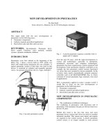
valve control system must be established. Fig.1 shows
the principle of valve control system with long pipeline
Fig.1 The principle of valve control system
(1) Pipe Dynamic Characteristics
Equation
[2][4]
Γ+Γ=
Γ+Γ=
)()(
)(
1
)()()(
)()()()()()(
221
221
sshsP
sZ
schsQsQ
sshsQsZschsPsP
C
C
Assume that the hydraulic source supply constant
pressure oil, the return pressure is zero and the length of
in-line and return line is equal, then we obtain
0)()()()()(
0)()()()()(
00
=Γ−Γ
=Γ+Γ
sshsQsZschsP
sshsQsZschsP
vCv
svCsv
)2(
)1(
where
)(sΓ
—propagation operator
)(sZ
c
characteristic impedance
(2) Four-way Slide valve Dynamic Equation
If orifice area of slide valve is matching and symmetric,
then the flow-pressure equation is
ρρ
vfsv
d
vfsv
dL
PPP
AC
PPP
ACQ
0
2
0
1
−+
−
−−
=
(3)
ρρ
vfsv
d
vfsv
dvsv
PPP
AC
PPP
ACQQ
0
2
0
10
−+
+
−−
==
(4)
where
−≤
−≥⋅+
=
W
A
X
W
A
XXWA
A
V
VV
10
10
10
1
,0
,
≥
≤⋅−
=
W
A
X
W
A
XXWA
A
V
VV
20
20
20
2
,0
,
1
A
is the orifice area of
AP →
or
TB →
,
2
A
is the
orifice area of
BP →
or
TA →
,
10
A
and
20
A
are the
orifice area of operating point,
W
is the area gradient,
v
X
is the relative motion of spool to operating point.
d
C
is the flow coefficient. The Laplace transforms of
Eq. (3) and Eq. (4) are as follows
)6()()()()()(
)5()()()()()(
00
00
sPKsPKsPKsXKsQ
sPKsPKsPKsXKsQ
vSsvSSfCSvQSsv
vsvSfCvQL
++−=
++−=
where
=⋅
≠⋅
−−
−++−−
=
∂
∂
=
0
0
,
,
)||(
)(
2010
2010
0
00
AA
AA
PPP
WC
PPPPPP
WC
X
Q
K
vfsv
d
vfsvvfsv
d
v
L
Q
ρ
ρ
f
L
C
P
Q
K
∂
∂
=
=⋅
≠⋅
−−
+
−+
+
−−
=
0
0
,
,
)
||
(
2
)(
2
2010
2010
0
2010
0
20
0
10
AA
AA
PPP
AAC
PPP
A
PPP
AC
vfsv
d
vfsvvfsv
d
ρ
ρ
=≥
−−
−
=≥
−−
≠⋅
−+
−
−−
=
∂
∂
−=
00,
||2
00,
||2
0,)(
2
1020
0
20
2010
0
10
2010
0
20
0
10
AA
PPP
AC
AA
PPP
AC
AA
PPP
A
PPP
AC
P
Q
K
vfsv
d
vfsv
d
vfsvvfsv
d
f
S
CS
ÇÒ
ÇÒ
ρ
ρ
ρ
=≥−−−
=≥−−
≠⋅−+−−−
=
∂
∂
=
00,||
00||
0)(
10200
20100
201000
AAPPP
WC
AAPPP
WC
AAPPPPPP
WC
X
Q
K
vfsv
d
vfsv
d
vfsvvfsv
d
v
S
QS
ÇÒ
ÇÒ£¬
£¬
ρ
ρ
ρ
CS
L
CS
S
L
S
K
P
Q
KK
P
Q
K −=
∂
∂
==
∂
∂
=
0
0
,
C
S
SC
S
S
SS
K
P
Q
KK
P
Q
K −=
∂
∂
==
∂
∂
=
0
0
,
(3) The Continuity Equation and Force
Balance Equation of Cylinder
)8()(
)7()(
4
2
2
EquationBalanceForce
FXK
dt
dX
B
dt
Xd
mPA
EquationContinuity
PC
dt
dP
E
V
dt
dX
AQ
Ltt
t
t
t
tft
fsl
f
y
tt
tL
+++=
⋅+⋅+=
where
t
A
and
t
X
are the area and motion of hydraulic
cylinder piston respectively,
Y
E
is the equivalent
volume elastic modulus,
t
V
is the general volume of
hydraulic cylinder,
sl
C
is the general leakage
coefficient. Eqs. (1), (2), (5), (6) together with the
Laplace transforms of Eq. (7) and Eq. (8) composed a
set equations, from which we can obtain the transfer
function of system as follows
v
t
X
X
sG
•
=)(
)9(
)1
2
()(2)1
2
(
)(2
'
2
2
1
2
2
1
+++++
+
=
s
s
KsGs
s
sGKK
h
h
h
C
h
h
h
vpv
ω
ξ
ωω
ξ
ω
where
))((
))((
)(
1
sch
sshZ
sG
C
Γ
Γ
=
tt
ty
h
Vm
AE
2
4
=ω
ty
t
t
t
t
ty
t
slC
h
mE
V
A
B
V
mE
A
CK
4
)(
+
+
=ξ
t
ty
Ct
CS
hh
V
mE
KA
K
2
'
−= ξξ
t
Q
v
A
K
K =
t
CSQSCQ
vp
A
KKKK
K
−
=
THEORETICAL ANALYSIS OF THE
INFLUENCES OF PIPE ON VALVE
CONTROL HYDRAULIC SYSTEM
When the influence of pipe is neglected
ssv
PP =
=constant
0
00
== PP
v
)(
1
sG
=0
The transfer function of system is
1
2
)(
2
2
'
++
==
•
s
s
K
X
X
sG
h
h
h
v
v
t
ω
ξ
ω
The influences of pipe on system can be measured by
the difference between
)(sG
and
)(
'
sG
.
While the difference in amplitude frequency and phase-
frequency characteristic is expressed by
|)(|
||)(||)(||
)(
'
ω
ωω
ω
jG
jGjG
e
A
−
=
and
|))(())((|)(
'
ωϕωϕω
ϕ
jGjGe −=
respectively, we can reach the following conclusion.
If
1|)(|)2(2
1
<<≤− EjGK
K
K
K
CS
Q
QS
C
ω
then
Ee
A
≤)(ω
and
Ee ≤)(ω
ϕ
The certification is neglected here
If we define
|)(|)2(2)(
1
ωω jGK
K
K
Ke
CS
Q
QS
C
−=
,
then
)(
ωe
can be used to measure the influences of pipe
on system approximately..
When slide valve is in different operating position, the
influences of pipe to system are discussed as follows
(i) Zero position
When slide valve is in zero position,
0==
CSC
KK
,
0)( =ωe
. Pipe has a little influence on the dynamic
characteristics of system. The actual value of
c
K
and
cs
K
aren’t zero but very small. So, the influence of pipe
to system is minimal under the condition
(2) Nonzero position
When slide valve is in nonzero position,
QSQ
KK =
,
CSC
KK =
,
|)(|2)(
1
ωω jGKe
C
=
It will be seen that if
C
K
is small enough, the influences
of pipe on system can be neglected. According to the
theory of fluid transmission lines,
|)(|
1
ωjG
reaches
maximal point at resonance frequency and fluctuates
periodically as frequency ascends. Accordingly,
)( ωjG
fluctuates periodically relating to
)(
'
ωjG
. The
fluctuation frequency is proportional to the length of
pipe. The fluctuation amplitude descends as frequency
ascends.
SIMULATION STUDY
It will be seen that the influences of pipe on hydraulic
system are related to the steady-state point of slide
valve. Slide valve is in zero position in position
control system and in nonzero position in velocity
control system. The following is the simulation study
of them.
(1) Position Control System
The simulation parameters are as follows:
2.137=
h
ω
1−
s
11
102.4
−
×=
C
K
12
102.3
−
×=
CS
K
5.0==
QSQ
KK
5.0=
h
ξ
495.0
'
=
h
ξ
250=
v
K
9
107.9
−
×=
vp
K
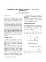
Fig.2 presents the frequency response characteristics of
valve control hydraulic system under different pipe
length. The simulation result shows:
the frequency response curve of system exists
periodic fluctuation
the fluctuation frequency is proportional to the length
of pipe.
the fluctuation amplitude reaches maximum near the
natural frequency of system and is smaller in low-
frequency and high-frequency stage
The frequency response is generally approximate to
second-order system.
Fig.2 The frequency response characteristic of system
when slide valve is in zero Position
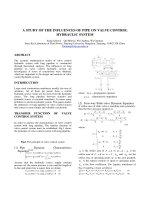
Fig.3 The frequency response characteristic of system
when slide valve is in nonzero position
50 100 150 200 250 300 350 400 450 500
-180
-160
-140
-120
-100
-80
-60
-40
-20
0
Phase-frequency characteristics
¦Ø£¨1/s£©
¦Õ£¨¦Ø£©
L=25m
L=50m
L=0m
50 100 150 200 250 300 350 400 450 500
-40
-30
-20
-10
0
10
20
30
40
50
Amplitude frequency characteristic
¦Ø£¨1/s£©
A£¨¦Ø£©£¨dB£©
L=0m
L=50m
L=25m
50 100 150 200 250 300 350 400 450 500
-250
-200
-150
-100
-50
0
50
100
Phase-frequency characteristic
¦Ø£¨1/s£©
¦Õ£¨¦Ø£©
L=25m
L=50m
L=0m
50 100 150 200 250 300 350 400 450 500
25
30
35
40
45
50
55
Amplitude frequency characteristic
¦Ø£¨1/s£©
A£¨¦Ø£©£¨dB£©
L=25m
L=50m
L=0m
(2) Velocity Control System
The simulation parameters are as follows
2.137=
h
ω
1−
s
11
102.4
−
×=
C
K
12
102.4
−
×=
CS
K
5.0==
QSQ
KK
5.0=
h
ξ
495.0
'
=
h
ξ
250=
v
K
0=
vp
K
Fig.3 presents the frequency response characteristics of
valve control hydraulic system under different pipe
length.
The simulation result shows:
the frequency response of system fluctuates
periodically.
the fluctuation amplitude descends when the
frequency ascends
the fluctuation frequency is proportional to the length
of pipe.
If the length of pipe or the value of
C
K
isn’t small
enough, the system can’t be considered as second-
orde system.
CONCLUSION
This paper has presented an accurate mathematical
model for valve control hydraulic system with long
pipeline. On the basis of the analysis to it, some
conclusions are reached.
1. The influences of pipe on system can be measured
approximately with the frequency domain criterion
|)(|)2(2)(
1
ωω jGK
K
K
Ke
CS
Q
QS
C
−=
2. For given pipe parameters,
c
K
decides the influences
of pipe on system in terms of ideal zero lap slide
valve.
3. Pipe makes the frequency response of system
fluctuating periodically. The fluctuation frequency is
proportional to the length of pipe. The fluctuation
amplitude is decided by valve coefficient, pipe elastic
modulo and pipe inner diameter.
4. The influences of pipe are greater to velocity control
system than to position control system.
REFERENCES
[1] T.J.Viersma, A.A.Ham, “Hydraulic Line
Dynamics”,1979.
[2]
1986
[3] H.E.1
976
[4] “
”1987
[5] .“
”
CAD
[6] .“
”
CAD
[7] “
”94
[8] Chen, Jine, “Theoretic solution of the transient flow
of liquid in the pipe with fluid Machinery”, Journal
of Hydrodynamics, v 4 n 4 Oct 1992. p 119-126