Bài giảng thủy lực - Tiếng anh - P2
Bạn đang xem bản rút gọn của tài liệu. Xem và tải ngay bản đầy đủ của tài liệu tại đây (674.71 KB, 7 trang )
NEW DEVELOPMENTS IN PNEUMATICS
Dr. Kurt Stoll
Festo AG & Co., Ruiterstr. 82, D-73734 Esslingen, Germany
ABSTRACT
This paper dealt with the new developments of
pneumatics in the following areas:
• Pneumatic components
• Industry segment specialized applications
• Best before-sales and after-sales services
KEYWORDS: Developments, Pneumatic drive,
Servo control, Field-bus, valve terminal, modular
systems, dynamic simulation, database
INTRODUCTION
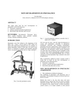
Pneumatics were first utilised at the beginning of the
fifties. Fig. 1 shows a device built in 1955, which was
fitted with single-acting aluminium die cast cylinders. A
typical pneumatic system of that time was used in this
device; it consisted of cylinders and manually operated
valves. An operator played the roll of a “logic controller”.
Fig. 1 An early pneumatic system
Fig. 2 A purely pneumatic sequence controller with 12
inputs and 12 outputs
Over the past 50 years, with the rapid developments in
science and technologies, especially in automation,
mechanical, electronic and computer technologies,
pneumatics has been experiencing a quick expansion and
development. Take automation sequence controllers as an
example, the first pneumatic control systems functioned
via valves that were actuated by driven camshafts. In the
seventies many purely pneumatically actuated sequence
controllers such as the QUICKSTEPPER (Fig. 2), which
consisted of several pneumatic logic elements, were used
in applications.
How is pneumatics applied in today’s modern world? I
would like to focus on the new developments in
pneumatics in the following areas:
• Pneumatic components
• Industry segment specialized applications
• Best before and after-sales services
NEW DEVELOPMENTS IN PNEUMATIC
COMPONENTS
o The combination of different techniques
The combining of pneumatics with electronics and of
pneumatics with mechanics became an obvious trend over
the last 10 years.
Behind this trend is the fact that more and more
pneumatic drives, sensors and valves are used in a modern
automatic machine. This means more inputs and outputs
are required in the control system. A purely pneumatic
control system is no longer suitable to meet present
demands. So in most machines today, PLCs or IPCs are
used as sequence controllers together with a large number
of electro-pneumatic converters, or solenoid valves.
As a result, the pneumatic suppliers are faced with
demands to improve the performance and to expand the
functions of pneumatic components. A pneumatic valve
should be easy to install and fast switching. A pneumatic
drive should be able to move faster and more precisely.
Sometimes an electro-pneumatic proportional valve is
required to convert a continuous electronic signal into
pneumatic signal.
All this resulted in the combination of pneumatics,
electronics and mechanics.
By combining pneumatics with mechanics, customers will
not only save engineering time with regard to designing
and testing, but also receive an optimised solution because
the product they receive is proven and tested by the
pneumatics manufacturer.
Fig. 3 shows a swivelling/linear unit, in which a linear
cylinder is combined with a rotary drive to get
independent linear and rotational movements.
Fig. 3 A swivelling/linear unit
Fig. 4 shows pneumatic units used in an assembling
system. This includes a linear and rotary cylinder
combined with a high precision guide unit. Excellent
precision and rigidity can be achieved with this
combination of components.
The “valve terminal” concept was introduced at the
beginning of the nineties. In recent years valve terminals
have been widely used. The origin of such a product is to
meet the demands of the larger scale control system. In a
valve terminal, the valves and electronic I/Os are
integrated in accordance with specific user interfaces (Fig.
5). Customers can order a valve terminal according to the
specification of their application. They will get a complete
factory
Fig.4 Pneumatic units with several precision
mechanical parts
pre-assembled and pre-tested unit. They can link the valve
terminal to a PLC or IPC via the desired interface, such as
multipin or fieldbus. They can even order a valve terminal
with a PLC already integrated. In this way, application
engineers can easily divide their control systems into a
couple of sub-systems. They obtain the sub-systems from
the suppliers with guaranteed functionalities. That is to
say, what the customers get are not only the components,
but also the whole solution, a solution that suits their
application.
Fig. 5 A valve terminal, the combination of pneumatics
and electronics
A valve terminal equipped with fieldbus connection
makes it possible for the pneumatic system to be
integrated as a part of a factory network.
Another example of combination and integration is shown
as Fig. 6, a pneumatic unit with the combination of a
cylinder, sensors, speed control valves and direction
control valve. Where the interfaces to the sensor and
direction valve could be fieldbus or individual
connections.
Fig. 7 is a multi controlled positioning system, a
pneumatic servo-positioning axis is combined with an
electrically driven axis. In this system, we can see that
both the guided pneumatic linear cylinder DGPL and the
guided electrical axis DGEL have the same mechanical
interfaces. This makes it much easier for customers to
design their machines.
Fig. 6 Cylinder, solenoid valve, speed control valves
and sensors in an integrated unit
Fig.7 Pneumatic and electrical drives with the same
mechanical interface
o Compact performance
In many applications, a pneumatic control valve is to be
mounted together with some moving parts of the machine.
In this case, the valve should be as light and as small as
possible. On the other hand, in order to shorten machine
cycle time, the control valves should be installed as close
to the cylinder as possible.
Fig. 8 provides a direct comparison of a solenoid valve
made in 1961 with one made in 1997, both valves have
the same flow rate (400 l/min) but the new generation of
solenoid valve is only 10 mm in width, while the old type
is 40 mm.
Fig.8 In comparison, valves of 1961 and 1997, the
same flow rate, but a quarter of the width
o More intelligence is integrated into products.
Faster movement is often desired on a machine. It is not
difficult to get a cylinder to move faster. But it is more
difficult to stop a fast moving cylinder properly (without
vibrations or shocks).
Fig. 9 shows a soft-stop cylinder, in which a displacement
sensor, a 5/3 dynamic proportional valve and a smart
controller are included. With such a system, the time
taken for the cylinder to travel from one end position to
the other can be reduced by 30%. In addition, 2 freely
selectable intermediate position settings are possible.
Fig.9 Fast speed and soft stop
Fig. 10 shows a pneumatic servo positioning system. A
digital smart controller is employed in such a system.
Fig.10 Smart pneumatic positioning axes
The controller is robust and suitable for industrial
applications. Built-in intelligence enables it to find the
optimised control parameters. The user needs only to
input the essential application data, such as the load,
stroke, diameter and so on. Or even more simply, in the
case of the SPC11 controller, just to push a “teach-in”
button.
o Cutting costs with the modular product concept
In a modern highly automated machine, the control
system often has many functions. One solution is to make
such products, in which all the necessary functions are
integrated, but this may incur high manufacturing costs.
Fig. 11 A modular valve terminal with 26 solenoid
valves and various electronic interfaces
A very elegant way is to use a modular product concept.
The benefit of a modular product for customers is that
they can order the products in modules which exactly
meet their requirements. They only pay for the functions
they need.
A modular valve terminal is shown in Fig. 11. Customers
can configure or select the number and the size of the
valves, the quantity of the electronic I/Os and so on.
Fig. 12 and Fig. 13 show modular vacuum components
and modular air service unit respectively.
Fig.12 A modular vacuum system with freely
combinable suction cup holder, angle
compensator, filter and suction cup
o Innovation, the new driving principle
A new single-acting pneumatic drive - fluidic muscle - is
shown in Fig. 14. It can output 10 times more force than a
standard cylinder of equivalent diameter. Fig. 14 shows
some applications of such a drive.
Fig. 13 A modular air service unit with manual on-off
valve, compressed air filter and regulator,
lubricator, soft-start valve, distributor and
pressure switch
Fig. 14 Fluidic muscle and some typical applications
It is well known that with a pneumatic cylinder it is very
difficult to achieve slow movement without the stick-slip
effect. To overcome this disadvantage electrically driven
cylinders of the same size and with the same installation
interfaces as standard pneumatic cylinders have been
developed and applied in applications. Customers don’t
need to make mechanical modifications to their machines.
TRENDS REGARDING APPLICATIONS
With regard to pneumatic applications, one of the most
important tasks today is to develop more and more
specialized products for the various industry segments.
Fig. 15 Pneumatic components for the food and packing
industry
Fig. 15 shows cylinders and valves that have been
specially developed for the food and packaging industry,
where high corrosion resistance and ease of cleaning are
essential.
The electronics and handling and assembly industry also
need pneumatic products that can meet special
requirements. Fig 4 shows some precisely guided
pneumatic drives with very high rigidity that are suitable
for use in the handling and assembling industry. Fig. 16
shows some miniature precisely guided pneumatic
actuators that suit the applications in the electronics
industry.