Động cơ Ford diesel 6.7L
Bạn đang xem bản rút gọn của tài liệu. Xem và tải ngay bản đầy đủ của tài liệu tại đây (2.44 MB, 157 trang )
FORD MOTOR COMPANY REVISION DATE: JANUARY 7, 2010 09.01.00.02-PAGE 1 OF 157
2011 MY OBD System Operation
Summary for 6.7L Diesel Engines
Table of Contents
Introduction – OBD-II and EMD .............................................................................................................................5
OBD-II Systems................................................................................................................................................5
EMD Systems...................................................................................................................................................5
General Description 6.7L Diesel Engine .................................................................................................................8
System Schematic 6.7L Chassis Certified........................................................................................................9
NON-METHANE HYDROCARBON (NMHC) CONVERTING CATALYST MONITOR.......................................13
Diesel Oxidation Catalyst Efficiency Monitor...................................................................................................13
Diesel Oxidation Catalyst DPF Regeneration Assistance Monitor..................................................................14
Diesel Oxidation Catalyst SCR Assistance Monitor........................................................................................14
OXIDES OF NITROGREN (NOx) CONVERTING CATALYST MONITORING...................................................15
Selective Catalyst Reduction Catalyst Efficiency Monitor...............................................................................15
Selective Catalyst Reduction Feedback Control Monitors..............................................................................17
Selective Catalyst Reduction Tank Level........................................................................................................18
MISFIRE MONITOR .............................................................................................................................................19
Misfire System Overview ................................................................................................................................19
Misfire Algorithm Processing ..........................................................................................................................19
FUEL SYSTEM MONITOR...................................................................................................................................21
Fuel System Overview....................................................................................................................................21
Fuel Rail Pressure Sensor Circuit Check........................................................................................................21
Fuel Rail Pressure Sensor Range Check: ......................................................................................................23
Injector Code Missing/Invalid:.........................................................................................................................30
Fuel system pressure control:.........................................................................................................................31
Fuel Rail Pressure Monitors:...........................................................................................................................31
Injection Timing / Injection quantity.................................................................................................................32
Zero Fuel Calibration: .....................................................................................................................................32
FORD MOTOR COMPANY REVISION DATE: JANUARY 7, 2010 09.01.00.02-PAGE 2 OF 157
Feedback control: ...........................................................................................................................................34
EXHAUST GAS SENSOR MONITOR..................................................................................................................38
Air-Fuel Ratio Sensors: Tailpipe NOx and O2 Sensor Control Module...........................................................38
EXHAUST GAS RECIRCULATION (EGR) SYSTEM MONITOR........................................................................44
EGR Rate System Monitor .............................................................................................................................44
EGR Cooler / EGR Cooler Bypass Monitor....................................................................................................45
EGR System Slow Response.........................................................................................................................48
EGR Closed-loop Control Limits Monitor........................................................................................................48
Mass Airflow Closed-loop Control Limits Monitor............................................................................................49
BOOST PRESSURE CONTROL SYSTEM MONITORING.................................................................................51
Intrusive Turbo Position and Response Monitoring ........................................................................................51
Intrusive Wastegate Monitoring ......................................................................................................................53
Functional Overboost Monitoring....................................................................................................................54
Functional Underboost Monitoring..................................................................................................................55
Threshold Underboost Monitoring ..................................................................................................................56
Charge Air Cooler Monitoring .........................................................................................................................57
PARTICULATE MATTER (PM) FILTER MONITORING......................................................................................58
DPF Filter Efficiency and Missing Substrate Monitors ....................................................................................58
DPF Frequent Regeneration Monitor..............................................................................................................59
DPF Incomplete Regeneration Monitor ..........................................................................................................60
DPF Feedback Control Monitors ....................................................................................................................61
DPF Restriction Monitor..................................................................................................................................62
CRANKCASE VENTILATION (CV) SYSTEM MONITOR....................................................................................63
ENGINE COOLING SYSTEM MONITORING......................................................................................................65
Thermostat Monitor.........................................................................................................................................65
Primary Coolant Temp Dynamic Monitoring...................................................................................................68
Secondary Coolant Temp Dynamic Monitoring..............................................................................................69
COLD START EMISSION REDUCTION STRATEGY MONITORING................................................................70
Cold Start Emission Reduction System Monitor .............................................................................................70
Cold Start Emission Reduction Component Monitor.......................................................................................71
Engine Sensors.....................................................................................................................................................74
Air Temperature Rationality Test ....................................................................................................................74
Barometric Pressure and Manifold Absolute Pressure ...................................................................................82
Turbine Upstream Pressure Sensor Plausibility Checks ................................................................................84
Upstream Turbine Pressure Sensor Signal Range Check .............................................................................85
EGR Valve Position Sensor............................................................................................................................86
Throttle Position Sensor..................................................................................................................................86
EGR Downstream Temperature Sensor Dynamic Plausibility Check.............................................................87
Engine Coolant & Engine Oil Correlation........................................................................................................88
FORD MOTOR COMPANY REVISION DATE: JANUARY 7, 2010 09.01.00.02-PAGE 3 OF 157
Cam and Crank Sensor:.................................................................................................................................91
Fan:.................................................................................................................................................................93
Mass Air Meter................................................................................................................................................94
MAF Rationality Check...................................................................................................................................96
DEF Pressure Sensor.....................................................................................................................................99
Reductant Pressure Sensor Signal Range Check........................................................................................100
Reductant Pressure Plausibility Check before Start-up ................................................................................100
DEF Pressure Build-up Check at Start-up....................................................................................................101
DEF System Pressure Control......................................................................................................................102
Reductant Tank Level Sensor ......................................................................................................................103
Reductant Tank Level Sensor Circuit Checks ..............................................................................................104
Reductant Tank Level Sensor Plausibility Check .........................................................................................105
Reductant Tank Temperature Sensor ..........................................................................................................105
Exhaust Gas Temperature Sensor Rationality Test......................................................................................108
Diesel Particulate Filter Pressure Sensor Rationality Test............................................................................111
Diesel Particulate Filter Pressure Offset Test ...............................................................................................112
Engine Outputs ...................................................................................................................................................113
EGR Valve Actuator Signal Range Check....................................................................................................113
EGR Valve Actuator Jammed Detection.......................................................................................................113
Throttle Valve Actuator Signal Range Check................................................................................................114
Throttle Valve Actuator Jammed Detection ..................................................................................................115
ECB Valve Actuator Signal Range Check....................................................................................................116
Urea System Pressure Control .....................................................................................................................116
Reductant Pump Motor.................................................................................................................................118
Reductant Dosing Valve (Injector)................................................................................................................121
Reverting Valve ............................................................................................................................................124
Urea Heaters ................................................................................................................................................126
Lack of Communication Codes:....................................................................................................................134
Glow Plugs....................................................................................................................................................136
Turbocharger Actuator Signal Range Check................................................................................................141
Wastegate Vacuum Solenoid Signal Range Check .....................................................................................141
Miscellaneous ECU Errors:...........................................................................................................................142
Comprehensive Component Monitor - Transmission .........................................................................................143
Transmission Inputs......................................................................................................................................143
Transmission Outputs...................................................................................................................................147
6R140 (RWD) Transmission with external PCM or TCM ...................................................................................151
On Board Diagnostic Executive ..........................................................................................................................154
Exponentially Weighted Moving Average ...........................................................................................................155
I/M Readiness Code............................................................................................................................................156
FORD MOTOR COMPANY REVISION DATE: JANUARY 7, 2010 09.01.00.02-PAGE 4 OF 157
Serial Data Link MIL Illumination.........................................................................................................................156
Calculated Load Value........................................................................................................................................157
FORD MOTOR COMPANY REVISION DATE: JANUARY 7, 2010 09.01.00.02-PAGE 5 OF 157
Introduction – OBD-II and EMD
OBD-II Systems
California OBD-II applies to all California and "Green State" gasoline engine vehicles up to 14,000 lbs. Gross
Vehicle Weight Rating (GVWR) starting in the 1996 MY and all diesel engine vehicles up to 14,000 lbs. GVWR
starting in the 1997 MY.
"Green States" are states that have adopted California emission regulations, starting in the 1998 MY. Green States
receive California vehicles for all light duty passenger cars and trucks. Green States are Massachusetts, New
York, Vermont for 2000, Maine for 2001, Rhode Island, Connecticut, Pennsylvania for 2008, New Jersey,
Washington, Oregon for 2009, Maryland, New Mexico for 2011, Arizona for 2012, and Florida for 2013.
Federal OBD-II applies to all gasoline engine vehicles up to 8,500 lbs. GVWR starting in the 1996 MY and all
diesel engine vehicles up to 8,500 lbs. GVWR starting in the 1997 MY.
Starting in the 2004 MY, Federal vehicle over 8,500 lbs. are required to phase in OBD-II. Starting in 2004 MY,
gasoline-fueled Medium Duty Passenger Vehicles (MDPVs) are required to have OBD-II. By the 2006 MY, all
Federal vehicles from 8,500 to 14,000 lbs. GVWR will have been phased into OBD-II.
OBD-II system implementation and operation is described in the remainder of this document.
EMD Systems
Engine Manufacturer Diagnostics (EMD) applies to all 2007 MY and beyond California gasoline-fueled and diesel
fueled on-road heavy duty engines used in vehicles over 14,000 lbs Gross Vehicle Weight Rating (GVWR). EMD
systems are required to functionally monitor the fuel delivery system, exhaust gas recirculation system, particulate
matter trap, as well as emission related ECM input inputs for circuit continuity and rationality, and emission-related
outputs for circuit continuity and functionality. EMD requirements are very similar to OBD-I system requirements.
As such, OBD-I system philosophy will be employed, the only change being the addition of some comprehensive
component monitor (CCM) rationality and functionality checks.
EMD vehicles use the same PCM, CAN serial data communication link, J1962 Data Link Connector, and PCM
software as the corresponding OBD-II vehicle. The only difference is a different PCM calibration.
The following list indicates what monitors and functions have been altered from OBD-II for EMD calibrations:
FORD MOTOR COMPANY REVISION DATE: JANUARY 7, 2010 09.01.00.02-PAGE 6 OF 157
Monitor / Feature Calibration
NON-METHANE HYDROCARBON (NMHC) CONVERTING CATALYST
MONITOR
Diesel Oxidation Catalyst Efficiency Monitor
Diesel Oxidation Catalyst DPF Regeneration Assistance Monitor
Diesel Oxidation Catalyst SCR Assistance Monitor
Same as OBD-II but does not set the MIL.
Same as OBD-II
Same as OBD-II
OXIDES OF NITROGREN (NOx) CONVERTING CATALYST MONITORING
Selective Catalyst Reduction Catalyst Efficiency Monitor
Selective Catalyst Reduction Feedback Control Monitors
Selective Catalyst Reduction Tank Level
Same as OBD-II.
Same as OBD-II.
Same as OBD-II.
Misfire Monitor Same as OBD-II but does not set the MIL.
FUEL SYSTEM MONITOR
Fuel Rail Pressure Sensor Circuit Check
Fuel Rail Pressure Sensor Range Check:
Injector Code Missing/Invalid:
Fuel system pressure control:
Fuel Rail Pressure Monitors:
Injection Timing / Injection quantity - Zero Fuel Calibration:
Feedback control:
Same as OBD-II
Same as OBD-II
Same as OBD-II
Same as OBD-II
Same as OBD-II
Same as OBD-II
Disabled
EXHAUST GAS SENSOR MONITOR
Air-Fuel Ratio Sensors: Tailpipe NOx and O2 Sensor Control Module
Same as OBD-II
EXHAUST GAS RECIRCULATION (EGR) SYSTEM MONITOR
EGR Rate System Monitor
EGR Cooler / EGR Cooler Bypass Monitor
EGR System Slow Response
EGR Closed-loop Control Limits Monitor
Mass Airflow Closed-loop Control Limits Monitor
Increased threshold from OBD-II
Same as OBD-II but does not set MIL.
Disabled
Disabled
Disabled
BOOST PRESSURE CONTROL SYSTEM MONITORING
Intrusive Turbo Position and Response Monitoring
Intrusive Wastegate Monitoring
Functional Overboost Monitoring
Functional Underboost Monitoring
Threshold Underboost Monitoring
Charge Air Cooler Monitoring
Same as OBD-II
Same as OBD-II
Same as OBD-II
Same as OBD-II
Same as OBD-II but with Increased
Thresholds.
Same as OBD-II
PARTICULATE MATTER (PM) FILTER MONITORING
DPF Filter Efficiency and Missing Substrate Monitors
DPF Frequent Regeneration Monitor
DPF Incomplete Regeneration Monitor
DPF Feedback Control Monitors
DPF Restriction Monitor
Same as OBD-II
Disabled
Disabled
Disabled
Same as OBD-II
Crank Case Ventilation Same as OBD-II but does not set the MIL.
Cold Start Emission Red Monitor Same as OBD-II, However, since the
dynamometer certified P473 vehicles do
no utilize a cold start strategy it is disabled.
FORD MOTOR COMPANY REVISION DATE: JANUARY 7, 2010 09.01.00.02-PAGE 7 OF 157
Comprehensive Component Monitor All circuit checks for components
supporting other EMD monitors, as well as
those for some of the other components,
are the same as OBD-II.
Glow Plug Resistance Monitor Same as OBD-II but does not set the MIL.
Idle Fuel Monitor Disabled
Idle Torque Monitor Disabled
Communication Protocol and DLC Utilizes CAN communication, same as
OBD-II, all generic and enhanced scan
tool modes work the same as OBD-II but
reflect the EMD calibration that contains
fewer supported monitors. "OBD
Supported" PID indicates EMD.
MIL Control Same as OBD-II
EMD system implementation and operation is a subset of OBD-II and is described in the remainder of this
document.
FORD MOTOR COMPANY REVISION DATE: JANUARY 7, 2010 09.01.00.02-PAGE 8 OF 157
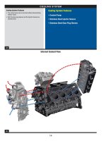
General Description 6.7L Diesel Engine
The 6.7L is a V8 engine designed to meet customer expectations of high horsepower and torque with exceptional
fuel economy and low NVH. It must do this while meeting the tough emissions standards set by the EPA and
CARB.
Some of the technologies employed to meet these diverse criteria include a Variable Geometry Turbocharger
(VGT), common rail fuel injection system, electronically controlled, cooled EGR, a diesel oxidation catalyst (DOC) ,
Selective Catalytic Reduction catalyst (SCR), Diesel Exhaust Fluid (DEF) injection system, and a diesel particulate
filter (DPF).
The system schematic on the next page shows the path of the air as it is compressed by the turbocharger, cooled
by the air-to-coolant intercooler, and mixed with the cooled EGR gases. The state of this compressed and heated
air is sensed by the manifold absolute pressure (MAP) sensor just before it enters the cylinders and the two
temperature sensors that represent Charge Air Cooler Outlet temperature (CACT1) and EGR Cooler outlet
temperature (EGRCOT). The exhaust gas pressure is measured by the exhaust backpressure (EP) sensor before
it exits through the turbocharger. The exhaust after treatment system consists of a DOC, a SCR, a DPF and a
muffler.
An electronic, proportional valve controls EGR rates with an integral position sensor (EGRP). Flows are
determined by valve position and the amount that backpressure exceeds boost pressure. An EGR throttle
(EGRTP) is used for regeneration control as well as to optimize the boost pressure vs. backpressure levels.
Fuel injection pressure is measured by the high-pressure fuel rail sensor (FRP). Injection pressure is controlled by
the high pressure pump and two regulating valves, a Pressure Control Valve (PCV), and a Fuel Metering Unit
(MeUn), formerly known as Volume Control Valve (VCV).
Engine speed (N) and crankshaft position are determined by the crankshaft position sensor (CKP) which senses a
60 minus 2 tooth target wheel. Camshaft position is determined by the camshaft position sensor (CMP), which
senses the profile of a multiple lobed camshaft.
Atmospheric pressure is determined by the Barometric Pressure sensor (BARO) mounted internally in the Engine
Control Module (ECM).
During engine operation, the ECM calculates engine speed from the crankshaft position sensor. The ECM
controls engine operation by controlling the piezo injector opening and closing times as well as the pressure at
which the fuel is injected, thereby controlling fuel quantity and timing. Simultaneously, airflow is modulated by
controlling the turbocharger vane position.
Fuel quantity is controlled by injector “on time” (pulse width) and the fuel rail pressure. Desired engine speed is
determined from the position of the accelerator pedal.
FORD MOTOR COMPANY REVISION DATE: JANUARY 7, 2010 09.01.00.02-PAGE 9 OF 157
System Schematic 6.7L Chassis Certified
ECT2
7
8
6
5
CDPFSCR
CMP_ H
CKP_H
E GRVC
EGRVP
DPFP _I
VGT C
FRPRV
Integ rate d
Glow Plug
Cont rol Modu le
Engine Cooling Fan
With Vistronic Clutch
3
4
2
1
MAF IAT
11
Air
Filter
Water to Air
Intercooler
TPSTACM +/ -
EGR_CO T
Reson ator
DOC
Firing Or der:
• Ford Cyl inder Numb er ing
• Ford Firi ng O rder 1-3-7-2-6-5-4-8
CACT 1 (T
21
)
INJ 1
INJ 4
INJ 3
IN J 2
INJ 8
INJ 7
INJ 6
INJ 5
Heat er #1
(line)
Heater #2 (tank)
Temp-Level
Urea Tank
Urea
Pressu re
Urea
Pump
SCR System (Reduc tant)
Urea
Injector
EGR CBV
2
ndary
Filter 2µ m
FDPS
E GT
11
DOC_IT1
EG T
12
DO C_ OT1
E GT
13
SCR_OT
D.
F.
C.
M .
WFS
Filte r 10µ
FVCV
Bos ch CP 4 HP P ump
FTS
FRPS
MAP
EGR
Cooler
U
T
U
P
U
T
n
n
U
T
U
T
U
Posn
P
U
Z
X
U
T
U
P
U
P
U
Posn
M
U
T
U
T
`
Hz
m
.
U
T
U
P
P
U
T
CAN2
PWM
T, Q
L
M
n
FC-V FSS
Temp S ensor
Pressu re Senso r
Pressu re Switch
Pu lse Ge nerator
Mass Flow / Frequ ency Out
U
T
P
U
P
U
Q
L
U
Posn
U
O
2
CAN2
NO
x
n
`
Hz
m
.
O2 S enso r
Quant ity/Level Sensor
Nox Sens or / C AN Ou t
Position Se nsor
U
Z
X
Imped ance Sen sor
Valve / Act uator
Po sitive Disp. Pump
CAN De vice/ Ctrlr
Vacuu m Solenoid
CANx
KEY
Note: GPC M co ntains hardwa re I/O
fo r GLOW & SCR heaters.
WGT_C V
P
Mech.
Vacuu m
Pump
EG T14
DPF_OT
U
T
NO
x
Sen sor
U
NO
x
CAN2
NO
x
Ctrl’r
Starter
Fuel
Cooler
ECT
U
T
EOL
EO P_ SW
Mech.
Coolant
Pump
LTC
Cooler
Fuel Tank
U
Q
L
T o Cluster
P3
U
P
ECT2
7
8
6
5
7
8
6
5
CDPFSCRSCR
CMP_ H
CKP_H
E GRVC
EGRVP
DPFP _I
VGT C
FRPRV
Integ rate d
Glow Plug
Cont rol Modu le
Engine Cooling Fan
With Vistronic Clutch
3
4
2
1
3
4
2
1
MAF IAT
11
Air
Filter
Air
Filter
Water to Air
Intercooler
Water to Air
Intercooler
TPSTACM +/ -
EGR_CO T
Reson atorReson ator
DOCDOC
Firing Or der:
• Ford Cyl inder Numb er ing
• Ford Firi ng O rder 1-3-7-2-6-5-4-8
CACT 1 (T
21
)
INJ 1INJ 1
INJ 4INJ 4
INJ 3INJ 3
IN J 2IN J 2
INJ 8INJ 8
INJ 7INJ 7
INJ 6INJ 6
INJ 5INJ 5
Heat er #1
(line)
Heater #2 (tank)
Temp-Level
Urea Tank
Urea
Pressu re
Urea
Pump
SCR System (Reduc tant)
Urea
Injector
EGR CBV
2
ndary
Filter 2µ m
2
ndary
Filter 2µ m
2
ndary
Filter 2µ m
FDPS
E GT
11
DOC_IT1
EG T
12
DO C_ OT1
E GT
13
SCR_OT
D.
F.
C.
M .
WFS
Filte r 10µ
FVCV
Bos ch CP 4 HP P ump
FTS
FRPS
MAP
EGR
Cooler
U
T
U
T
U
P
U
P
U
T
U
T
nn
nn
U
T
U
T
U
T
U
T
U
Posn
U
Posn
PP
U
Z
X
U
Z
X
U
T
U
T
U
P
U
P
U
P
U
P
U
Posn
U
Posn
MM
U
T
U
T
U
T
U
T
`
Hz
m
.
`
Hz
m
.
U
T
U
T
U
P
U
P
PP
U
T
U
T
CAN2CAN2
PWM
T, Q
L
PWM
T, Q
L
M
nn
FC-V FSS
Temp S ensor
Pressu re Senso r
Pressu re Switch
Pu lse Ge nerator
Mass Flow / Frequ ency Out
U
T
U
T
PP
U
P
U
P
U
Q
L
U
Q
L
U
Posn
U
Posn
U
O
2
U
O
2
CAN2
NO
x
CAN2
NO
x
nn
`
Hz
m
.
`
Hz
m
.
O2 S enso r
Quant ity/Level Sensor
Nox Sens or / C AN Ou t
Position Se nsor
U
Z
X
U
Z
X
Imped ance Sen sor
Valve / Act uator
Po sitive Disp. Pump
CAN De vice/ Ctrlr
Vacuu m Solenoid
CANxCANx
KEY
Note: GPC M co ntains hardwa re I/O
fo r GLOW & SCR heaters.
WGT_C V
PP
Mech.
Vacuu m
Pump
EG T14
DPF_OT
U
T
U
T
NO
x
Sen sor
U
NO
x
CAN2CAN2
NO
x
Ctrl’r
StarterStarter
Fuel
Cooler
Fuel
Cooler
ECT
U
T
U
T
EOL
EO P_ SW
Mech.
Coolant
Pump
LTC
Cooler
LTC
Cooler
Fuel Tank
U
Q
L
U
Q
L
T o Cluster
P3
U
P
FORD MOTOR COMPANY REVISION DATE: JANUARY 7, 2010 09.01.00.02-PAGE 10 OF 157
Actuators Acronym Sensors Acronym
DEF (Reductant) System
DEF Pump DEF Temp-Level Combination
Sensor
DEF Tank Heater Heater #1 DEF Pressure Sensor
DEF Pump & Line Heater Heater #2
DEF Injector
NOx Sensor System
NOx Sensor Controller NOx Sensor
Boost System
Variable Geometry Turbo Control VGTC Manifold Pressure Sensor MAP
Turbocharger Wastegate
Vacuum Control Solenoid
WGT_CV Charge Air Cooler Temperature
at Outlet
CACT1
Mass Airflow Sensor MAF
Intake Air Temperature IAT11
Exhaust Back Pressure EBP or P3
Exhaust Gas Recirculation System
Exhaust Gas Recirculation Valve
Control
EGRVC Exhaust Gas Recirculation Valve
Position
EGRVP
Exhaust Gas Recirculation
Cooler Bypass Vacuum Control
Solenoid
EGRCBV Exhaust Gas Recirculation
Cooler Gas Temperature at
Outlet
EGR_COT
EGR Throttle Motor Control TACM EGR Throttle Position Sensor TPS
Fuel System
High Pressure Fuel Volume
Control Valve
FVCV High Pressure Fuel Rail Pressure
Sensor
FRPS
High Pressure Fuel Pressure
Relief Valve
FRPRV Low Pressure Fuel Delivery
Switch
FDPS
Fuel Injectors INJ 1-8 Low Pressure Fuel Temperature
Sensor
FTS
Low Pressure Fuel Pump and
Filters
DFCM
Water In Fuel Sensor WFS
Fuel Tank Level Sensor
Glow Plug System
Glow Plugs
Glow Plug Controller GPCM
Exhaust System
Diesel Oxidation Inlet
Temperature
DOC_IT or EGT11
Diesel Oxidation Outlet
Temperature
DOC_OT or EGT12
Selective Catalytic Reduction
Outlet Temperature
SCR_OT or EGT 13
Upstream Catalyzed Diesel
Particulate Filter Pressure
DPFP
Downstream Diesel Particulate
Filter Temperature
DPF_OT or EGT 14
Engine System
Electric Clutch Fan Controller FC-V Cam Shaft Position Sensor CMP
Engine Coolant Temperature ECT
Crank Shaft Position Sensor CKP
Engine Oil Temperature EOT
Engine Oil Pressure Switch EOP_SW
Low Temperature Coolant Loop
Temperature
ECT2
Engine Fan Speed Sensor FSS
Environmental Temperature
Sensor
ENV_T
Barometric Pressure Sensor BP
FORD MOTOR COMPANY REVISION DATE: JANUARY 7, 2010 09.01.00.02-PAGE 11 OF 157
The dynamometer certified application of the 6.7L diesel engine has a similar layout to the chassis certified version.
The main differences are the use of a single compressor stage on the boost system, lack of a wastegate, and a
change in the order of the aftertreatment systems.
Dynamometer certified 6.7L exhaust system layout.
FORD MOTOR COMPANY REVISION DATE: JANUARY 7, 2010 09.01.00.02-PAGE 12 OF 157
2011 MY 6.7L V8 Diesel Exhaust Features, Medium Duty, Chassis Cert
2011 MY 6.7L V8 Diesel Exhaust Features, Medium Duty, Dyno Cert
6.7 F-250
Superduty Diesel
Exhaust System
Architecture
Pt-Pd DOC
Cu-
Zeolite
SCR
cDPF
Tailpipe
Engine
Out
DEF (urea)
Injector
6.7 F-250
Superduty Diesel
Exhaust System
Architecture
Pt-Pd DOC
Cu-
Zeolite
SCR
cDPF
Engine
Out
Tailpipe
FORD MOTOR COMPANY REVISION DATE: JANUARY 7, 2010 09.01.00.02-PAGE 13 OF 157
NON-METHANE HYDROCARBON (NMHC) CONVERTING CATALYST MONITOR
Diesel Oxidation Catalyst Efficiency Monitor
The Diesel Oxidation Catalyst (DOC) is monitored to ensure it is capable of converting hydrocarbons and carbon
monoxide. The monitor is only run during aftertreatment regeneration events. After entering regen, there is a short
delay to allow the DOC to achieve light-off temperature. Then the exotherm is monitored for a short period of time
and normalized versus an expected exotherm (a function of post-injection fuel quantity and ambient air temp). The
exotherm is defined as the DOC outlet temperature (EGT12) minus the DOC inlet temperature (EGT11). The
normalized exotherm is filtered for a short period of time, and then compared to a threshold. If the normalized
exotherm is below the threshold, a fault is indicated. No other preconditioning is required.
DOC Efficiency Monitor Summary:
DTCs P0420 – Catalyst System Efficiency Below Threshold
Monitor execution Once per driving cycle during which an active DPF regeneration occurs
Monitor Sequence None
Sensors OK EGT11, EGT12, TCO, MAF, IAT
Monitoring Duration 4 minutes
Typical DOC Efficiency Monitor Entry Conditions:
Entry condition Minimum Maximum
DPF regeneration event
Engine speed 1000 rpm 3000 rpm
Torque set point 100 Nm 1000 Nm
Engine coolant temperature 70 deg C
DOC inlet temperature 200 deg C 500 deg C
PTO inactive
Typical DOC Efficiency Monitor Malfunction Threshold:
Normalized exotherm is less than 40% of the expected exotherm for 60 seconds
FORD MOTOR COMPANY REVISION DATE: JANUARY 7, 2010 09.01.00.02-PAGE 14 OF 157
Diesel Oxidation Catalyst DPF Regeneration Assistance Monitor
The DOC is monitored to ensure it is capable of generating a sufficient exotherm to allow DPF regeneration events
by burning the soot which is stored in the Diesel Particulate Filter (DPF). This is accomplished with the same
diagnostic described above for the DOC Catalyst Efficiency Monitor.
Diesel Oxidation Catalyst SCR Assistance Monitor
The DOC in this system is not utilized to provide any changes in the feedgas constituency that would aid in the
proper SCR operation.
FORD MOTOR COMPANY REVISION DATE: JANUARY 7, 2010 09.01.00.02-PAGE 15 OF 157
OXIDES OF NITROGREN (NOx) CONVERTING CATALYST MONITORING
Selective Catalyst Reduction Catalyst Efficiency Monitor
The SCR catalyst is monitored to ensure it is capable of NOx conversion. The concentration of NOx upstream of
the SCR is calculated based on a model. NOx concentration downstream of the SCR is measured with a NOx
sensor. Using these concentrations, the cumulative efficiency of the SCR catalyst is calculated and compared to a
threshold. If the cumulative efficiency is below this threshold for a sufficient period of time, a fault will be indicated.
The reductant, Diesel Exhaust Fluid (DEF), which is used as part of the SCR catalyst reaction, is monitored to
ensure the tank is not refilled with an improper reductant. Upon detection of a refill event, the monitor is activated.
After the SCR Catalyst Efficiency Monitor has completed and the SCR has been determined to be functional, the
efficiency monitor continues to calculate the cumulative efficiency of the system. Each subsequent value for
cumulative efficiency is included in two filtering routines, one for short term efficiency and the other for long term
efficiency. If the difference between the two filtered efficiencies becomes greater than a threshold, a fault is
indicated. the short term efficiency needs to be less than 0.20 and the delta between short and long term efficiency
needs to be greater than 0.10.
Monitor Summary:
DTCs P20EE – SCR NOx Catalyst Efficiency Below Threshold
P207F – Reductant Quality Performance
Monitor execution P20EE - Once per driving cycle
P207F – After detection of a Diesel Exhaust Fluid refill
Monitor Sequence P20EE test followed by P207F test
Sensors OK NOx, EGT12, EGT13, ECT, DEF injection system, MAF, BP, O2,
DPFP, EGR system
Monitoring Duration P20EE – 2 Minutes, P207F – Dependent on driving conditions
FORD MOTOR COMPANY REVISION DATE: JANUARY 7, 2010 09.01.00.02-PAGE 16 OF 157
Typical Entry Conditions:
Entry condition Minimum Maximum
SCR Feedback Control Enabled
Short term efficiency 0.2
Short term to long term efficiency delta 0.1
Regeneration Cycle Not Requested
Engine coolant temperature 70 deg C
Ambient air temperature -6.7 degC
Barometric Pressure 82.5 kPa 120 kPa
Engine Speed 1000 rpm 3000 rpm
Torque Transients -30 N-m/s, +10 N-m/s
Exhaust Space Velocity 5000 120,000
SCR Inlet temp 200 degC 350 degC
DEF storage 30% understored 40% overstored
Diesel Exhaust Fluid refill detected (only for
Reductant Quality Performance monitor)
Typical Malfunction Thresholds:
P20EE: If the cumulative efficiency of the SCR Catalyst is less than 25% for approx 60 seconds., a fault is
indicated.
P207F: the short term Nox efficiency needs to be less than 0.20 and the delta between short and long term
efficiency needs to be greater than 0.10. This generally occurs in a highway drive cycle within 15 miles when
conditions are present.
FORD MOTOR COMPANY REVISION DATE: JANUARY 7, 2010 09.01.00.02-PAGE 17 OF 157
Selective Catalyst Reduction Feedback Control Monitors
The SCR system is monitored to ensure the proper closed loop control of the reductant injection. As part of the
reductant injection control, a correction factor is adapted to account for long term drift of the system (injector, etc).
This correction factor is monitored continuously. If the correction factor reaches a threshold in the positive or
negative direction for a sufficient period of time, a fault will be indicated.
A SCR Time to Closed Loop monitor is implemented to ensure that SCR feedback occurs when expected. Once
entry conditions are met, a timer is incremented. If the fraction of time in closed loop control is less than a
threshold, a fault is indicated.
Monitor Summary:
DTCs P249D – SCR Feedback at Minimum Limit
P249E – SCR Feedback at Maximum Limit
P249C – SCR Time to Closed Loop
Monitor execution Continuous
Monitor Sequence None
Sensors OK NOx, EGT12, EGT13,TCO, EGT11 EGT14, MAF, BP, IAT, DPFP,
and EGR system
Monitoring Duration 5 minutes
Typical Entry Conditions:
Entry condition Minimum Maximum
Low Temp Adaptation is enabled
(Feedback monitor only)
Engine speed 800 rpm 3000 rpm
Torque set point 0 Nm 1000 Nm
Barometric pressure 75 kPa
Ambient temperature -6.7 deg C
Engine coolant temperature 70 deg C
SCR temperature 160 deg C 900 deg C
Typical Malfunction Thresholds:
P249D: If the correction factor is clipped at its minimum value for 30 seconds then a fault is indicated.
P249E: If the correction factor is clipped at its maximum value for 5 minutes then a fault is indicated.
P249C: The error is set as soon as the fraction of closed loop operation vs expected is less than the threshold.
The monitor needs to run for 120 seconds to call it complete.
FORD MOTOR COMPANY REVISION DATE: JANUARY 7, 2010 09.01.00.02-PAGE 18 OF 157
Selective Catalyst Reduction Tank Level
The SCR system is monitored to ensure the level of DEF in the reductant tank is sufficient to achieve system
performance. As part of the DEF level customer warning system, a fault will be recorded when the calculated
mileage remaining of DEF is equal to 200 miles (The discrepancy between actual and reported mileage is due to
expected tolerance of calculations). The calculated mileage remaining is derived from the three pin level sensor in
the tank and the volume of DEF commanded to be injected over distance. This fault will be erased once the
system senses a DEF refill event.
Monitor Summary:
DTCs P203F - Reductant Level Too Low
Monitor execution Continuous
Monitor Sequence None
Sensors OK DEF Temp-Level Combination Sensor
Appears at Threshold. Chime 4 times and repeat every 5
minutes, Flashing Icon synchronized to chimes, re-
settable message.
Oil Change
Interval
Reported Level
8,500 mi
Ford Example Cluster Information
800 mi
On Request: (System Check)
How?
EXHAUST FLUID
RANGE: 800 Mi
300 mi
EXHAUST FLUID
RANGE: 300 Mi
Appears at Threshold & Every Key Cycle After. Mileage
shown will count-down. DTE Can be accessed by system
check, Solid Icon.
-100 mi
ENGINE IDLED
UPON REFUEL
X OVERRIDES
AVAILABLE
ENGINE IDLED
SEE MANUAL
RESET
Appears at Threshold and Every Key Cycle After / DTE
Can be accessed by system check
EXHAUST FLUID
EMPTY
RESET
RESET
RESET
RESET
RESET
RESET
EXHAUST FLUID
LEVEL OK
Appears at Threshold & Every Key Cycle After. Mileage
shown will count-down. DTE Can be accessed by system
check, Chime 4 times on key cycle, Solid Icon. Count
Down tied to Odometer from 299 actual miles.
99 mi
SPEED LIMITED
55 MPH IN 99Mi
EXHAUST FLUID
LOW
RESET
0 mi
55 MPH MAX UPON
RESTART
EXHAUST FLUID
EMPTY
SPEED LIMITED
TO 55 MPH
Appears at Threshold. Chime 4 times and repeat every 5
minutes, Flashing Icon synchronized to chimes, re-
settable message.
RESET
EXHAUST FLUID
EMPTY
RESET
EXHAUST FLUID
EMPTY
50 MPH MAX UPON
RESTART
RESET
EXHAUST FLUID
EMPTY
SPEED LIMITED
TO 50 MPH
RESET
RESET
RESET
RESET
RESET
0 mi
DEF Override countdown 5-4-3-2-1-NO
EXHAUST FLUID
UNDER HALF FULL
Or
RESET notes
the ability
to press the
Reset or Info
or OK Button.
restart
restart
refuel
Appears at Threshold. Chime 4 times and repeat every 5
minutes, Flashing Icon synchronized to chimes, re-
settable message.
Appears at Threshold. Chime 4 times and repeat every 5
minutes, Flashing Icon synchronized to chimes, re-
settable message.
Appears at Threshold. Chime 4 times and repeat every 5
minutes, Flashing Icon synchronized to chimes, re-
settable message.
Appears at Threshold. Chime 4 times and repeat every 5
minutes, Flashing Icon synchronized to chimes, re-
settable message.
P203F
Appears at Threshold. Chime 4 times and repeat every 5
minutes, Flashing Icon synchronized to chimes, re-
settable message.
Oil Change
Interval
Reported Level
8,500 mi
Ford Example Cluster Information
800 mi
On Request: (System Check)
How?
EXHAUST FLUID
RANGE: 800 Mi
300 mi
EXHAUST FLUID
RANGE: 300 Mi
Appears at Threshold & Every Key Cycle After. Mileage
shown will count-down. DTE Can be accessed by system
check, Solid Icon.
-100 mi
ENGINE IDLED
UPON REFUEL
X OVERRIDES
AVAILABLE
ENGINE IDLED
SEE MANUAL
RESET
Appears at Threshold and Every Key Cycle After / DTE
Can be accessed by system check
EXHAUST FLUID
EMPTY
RESET
RESET
RESET
RESET
RESET
RESET
EXHAUST FLUID
LEVEL OK
Appears at Threshold & Every Key Cycle After. Mileage
shown will count-down. DTE Can be accessed by system
check, Chime 4 times on key cycle, Solid Icon. Count
Down tied to Odometer from 299 actual miles.
99 mi
SPEED LIMITED
55 MPH IN 99Mi
EXHAUST FLUID
LOW
RESET
0 mi
55 MPH MAX UPON
RESTART
EXHAUST FLUID
EMPTY
SPEED LIMITED
TO 55 MPH
Appears at Threshold. Chime 4 times and repeat every 5
minutes, Flashing Icon synchronized to chimes, re-
settable message.
RESET
EXHAUST FLUID
EMPTY
RESET
EXHAUST FLUID
EMPTY
50 MPH MAX UPON
RESTART
RESET
EXHAUST FLUID
EMPTY
SPEED LIMITED
TO 50 MPH
RESET
RESET
RESET
RESET
RESET
0 mi
DEF Override countdown 5-4-3-2-1-NO
EXHAUST FLUID
UNDER HALF FULL
Or
RESET notes
the ability
to press the
Reset or Info
or OK Button.
restart
restart
refuel
Appears at Threshold. Chime 4 times and repeat every 5
minutes, Flashing Icon synchronized to chimes, re-
settable message.
Appears at Threshold. Chime 4 times and repeat every 5
minutes, Flashing Icon synchronized to chimes, re-
settable message.
Appears at Threshold. Chime 4 times and repeat every 5
minutes, Flashing Icon synchronized to chimes, re-
settable message.
Appears at Threshold. Chime 4 times and repeat every 5
minutes, Flashing Icon synchronized to chimes, re-
settable message.
P203F
FORD MOTOR COMPANY REVISION DATE: JANUARY 7, 2010 09.01.00.02-PAGE 19 OF 157
MISFIRE MONITOR
Misfire System Overview
The 6.7L Diesel engine utilizes a Hall Effect sensor (CKP) that processes the edges of a 60-2 tooth stamped target
wheel mounted on the crankshaft. The software gets an edge every 3 degrees and these edges are used for fuel
injection timing, fuel quantity control, and the calculation of engine speed. A software algorithm corrects for
irregularities of the teeth of the target wheel to improve crankshaft signal resolution. A second Hall effect sensor is
used to processes the edges of the three-lobed camshaft (CMP) target. The CMP signal and the window of 2
missing teeth on the crankshaft target wheel indicate proper camshaft to crankshaft position for correct cylinder
timing.
Misfire Algorithm Processing
The Misfire Monitor divides two rotations of the crankshaft into 16 half-segments, each 45 degrees of crankshaft
rotation. The crankshaft speed shows increases due to combustion of fuel in the cylinder followed by decreases
due to friction and other forces between cylinder firing events. The location of the half-segments is chosen such
that for each cylinder one half-segment contains the majority of the higher crankshaft speed values (the "high" half-
segment) and the other half-segment the majority of the lower crankshaft speed values (the "low" half-segment).
The range of crankshaft speed within each half-segment is averaged. The sum of the eight low half-segment
speeds is subtracted from the sum of the eight high half-segment speeds and the result divided by eight to get an
average increase in speed due to combustion. The Misfire Monitor then calculates the difference between the high
and low half-segments for a specific cylinder combustion event and increments a misfire counter for the firing
cylinder if this value is less than 20% of the average increase in speed due to combustion described above.
The Misfire Monitor collects blocks of data consisting of 20 crankshaft rotations. Upon achieving the correct entry
conditions for the Misfire Monitor as described below, the first block of 20 rotations is discarded to ensure stable
idle operation. All subsequent blocks of data are counted unless vehicle conditions change such that the entry
conditions are no longer satisfied. In this case, any data in the current partial block are discarded, along with the
data from the block immediately prior, as stable idle cannot be ensured for these data. The Misfire Monitor
completes once 50 valid blocks (1000 crankshaft revolutions) have been collected, and a fault is reported if a
cylinder shows 350 or more misfire events (out of 500 possible combustion events) in this time.
Certain engine operating parameters are monitored to ensure misfire operates in a region that yields accurate
misfire results. The table below outlines the entry conditions required for executing the misfire monitor algorithm.
FORD MOTOR COMPANY REVISION DATE: JANUARY 7, 2010 09.01.00.02-PAGE 20 OF 157
Misfire Monitor Operation:
DTCs P0300 – Random Misfire Detected
P0301 – Cylinder 1 Misfire Detected
P0302 – Cylinder 2 Misfire Detected
P0303 – Cylinder 3 Misfire Detected
P0304 – Cylinder 4 Misfire Detected
P0305 – Cylinder 5 Misfire Detected
P0306 – Cylinder 6 Misfire Detected
P0307 – Cylinder 7 Misfire Detected
P0308 – Cylinder 8 Misfire Detected
Monitor execution Continuous, at idle
Monitor Sequence None
Sensors OK Engine Coolant Temperature (ECT), Vehicle Speed (VSS), Crankshaft
Position Sensor (CKP) Injector Faults, Injector Bank Faults
Monitoring Duration 1000 revs
Typical Misfire Monitor Entry Conditions:
Entry condition Minimum Maximum
Engine Speed (Idle) 500 rpm 1150 rpm
Engine Coolant Temperature (ECT) -7 deg C
Vehicle Speed (VSS) <= 2 km/hr
Total fuel mass 2.0 mg/stroke
40.0 mg/stroke
FORD MOTOR COMPANY REVISION DATE: JANUARY 7, 2010 09.01.00.02-PAGE 21 OF 157
FUEL SYSTEM MONITOR
Fuel System Overview
Fuel injection pressure is measured by the high-pressure fuel rail sensor (FRP). Injection pressure is controlled by
the high pressure pump and two regulating valves, a Pressure Control Valve (PCV), and a Fuel Metering Unit
(MeUn), formerly known as Volume Control Valve (VCV).
PCV
HP PUMP
(ITP)
FUEL RAIL
Fuel Rail
DIESEL FUEL
CONDITIONING
MODULE (DFCM)
CONTAINS
LIFT PUMP
PRIMARY FILTER
AND WIF
CHASSIS FRAME
MOUNTED
FUEL TANK
CHASSIS
FRAME
MOUNTED
SUPPLY
RETURN
INJECTORS
LEAK OFF RAIL
WATER
BLEED
FUEL
COOLER
230 l/hr requirement at:
70
o
C Continuous
80
o
C Intermittent
90
o
C Limit
180 l/hr maximum at:
140 - 150
o
C Limit
To 1.1 bar gage
22 – 25 l/hr max.:
140 - 150
o
C
3 to 10 bar
95 l/hr at:
2 - 5
o
C above Inlet
To 1.1 bar
INJECTORS
SECONDARY
FUEL
FILTER.
ENGINE
MOUNTED
Fuel Rail Pressure Sensor Circuit Check
Fuel Rail Pressure ( FRP ) Sensor Circuit Check:
DTCs P0192 - Fuel Rail Pressure Sensor A Circuit Low Input
P0193 - Fuel Rail Pressure Sensor A Circuit High Input
Monitor Execution Continuous
Monitor Sequence None
Sensors OK Sensor Supply Voltage 1 OK (P06A6)
Typical Monitoring Duration 0.5 sec
Typical Fuel Rail Pressure Sensor Circuit Check Malfunction Thresholds:
FRP voltage < 0.13 V, or > 3.17 V
FORD MOTOR COMPANY REVISION DATE: JANUARY 7, 2010 09.01.00.02-PAGE 22 OF 157
Fuel Rail Pressure ( FRP ) Rationality Check Operation:
DTCs P0191 - Fuel Rail Pressure Sensor "A" Circuit Range/Performance
Monitor Execution Immediately Prior to Crank and After Key-off
Monitor Sequence None
Sensors OK Sensor Supply Voltage 1 OK (P06A6), FRP OK (P0192, P0193)
Typical Monitoring Duration 0.5 sec
Typical Fuel Rail Pressure Rationality Check Entry Conditions:
Entry condition Minimum Maximum
Pre-crank: engine coolant temperature -7 deg C
Pre-crank: time engine off 600 sec
After key-off: fuel temperature -40 deg C
After key-off: time since key off 12 sec
Typical Fuel Rail Pressure Rationality Malfunction Thresholds:
FRP voltage < 0.251 V (-40 bar) or > 0.384 V (68 bar).
FORD MOTOR COMPANY REVISION DATE: JANUARY 7, 2010 09.01.00.02-PAGE 23 OF 157
Fuel Rail Pressure Sensor Range Check:
When fuel rail pressure is controlled by the Pressure Control Valve, the Pressure Control Valve signal needed to
maintain rail control is compared to an expected value. An adaptation factor for the Pressure Control Valve is
calculated from the difference between observed and expected control values. Inaccuracy in the Rail Pressure
Sensor Signal Slope is a potential cause of inaccuracy in the needed Pressure Control Valve signal along
with physical errors in the PCV itself. If the adaptation factor required for the Pressure Control Valve
exceeds a minimum or maximum control limit, then a code is set for rail pressure slope out of acceptable
range.
Fuel Rail Pressure ( FRP ) Range Check Operation:
DTCs P016D - Excessive Time To Enter Closed Loop Fuel Pressure Control
P228E - Fuel Pressure Regulator 1 Exceeded Learning Limits - Too Low
P228F - Fuel Pressure Regulator 1 Exceeded Learning Limits - Too High
Monitor Execution Continuous
Monitor Sequence None
Sensors OK Sensor Supply Voltage 1 (P06A6), FRP (P0192, P0193)
Typical Monitoring Duration P016D – 30 sec, P228E, P228F - 10 sec
Typical Fuel Rail Pressure Range Check Entry Conditions:
Entry condition Minimum Maximum
P016D:
Requested rail pressure 500 bar 1200 bar
Change in requested rail pressure 30 sec
Fuel temperature 40 deg C
P228E, P228F:
Rail pressure set point 500 bar 1200 bar
Fuel Temperature 40 deg C
Time since engine start 30 sec
Typical Fuel Rail Pressure Range Check Malfunction Thresholds:
P016D: If the system is within the adaptation operating conditions, but fails to learn a new adaptation factor
after 30 seconds, this DTC is set.
P228E, P228F: If the adaptation factor exceeds positive or negative thresholds which correspond to
approximately a 20% deviation in the Rail Pressure Sensor slope, a DTC is set.
FORD MOTOR COMPANY REVISION DATE: JANUARY 7, 2010 09.01.00.02-PAGE 24 OF 157
Fuel Temperature Sensor Circuit Check Operation:
DTCs P0181 – Fuel Temperature Sensor "A" Circuit Range/Performance
P0182 – Fuel Temperature Sensor "A" Circuit Low
P0183 – Fuel Temperature Sensor "A" Circuit High
Monitor Execution Continuous
Monitor Sequence None
Sensors OK None
Typical Monitoring Duration 0.5 sec
Typical Fuel Temperature Sensor Circuit Check Entry Conditions:
Entry condition Minimum Maximum
P0181:
Engine Off Time 8 hours
Typical Fuel Temperature Sensor Circuit Check Malfunction Thresholds:
P0181: If after an 8 hour engine off soak, the difference in temperature between the fuel temperature sensor
and the charge air cooler outlet temperature sensor exceeds 16 deg C or if the difference in temperature
between the fuel temperature sensor and the charge air cooler outlet temperature sensor exceeds 13.2 deg C
and no active block heater is detected, a DTC is set
FTS voltage < 0.0946 V (0.122.4 V = 150 deg C) or > 4.918 V (4.762 V = -40 deg C)
FORD MOTOR COMPANY REVISION DATE: JANUARY 7, 2010 09.01.00.02-PAGE 25 OF 157
Volume Control Valve (VCV) Monitor Operation:
DTCs P0001 - Fuel Volume Regulator Control Circuit / Open
P0002 - Fuel Volume Regulator Control Circuit Range/Performance
P0003 - Fuel Volume Regulator Control Circuit Low
P0004 - Fuel Volume Regulator Control Circuit High
Monitor Execution Continuous
Monitor Sequence None
Sensors OK None
Typical Monitoring Duration 0.3 sec
Typical Volume Control Valve Monitor Malfunction Thresholds:
P0001 – If the volume control valve is not energized and the voltage from the volume control valve control chip
is in the range 2.8 – 4.8 V (normal operation: electrical system voltage (~13.5V)
P0002 – Temperature of powerstage driver on ECM > 170 deg C
P0003 – If the volume control valve is not energized and the observed voltage from the volume control valve
control chip is less than 2.8V (normal operation: electrical system voltage (~13.5V)
P0004 – If the volume control valve is energized and the current to the volume control valve exceeds 3.7A
(normal operation: 2.2A maximum)