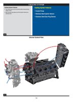
Tài liệu động cơ FORD 6.4L P1- Chapter 4
Bạn đang xem bản rút gọn của tài liệu. Xem và tải ngay bản đầy đủ của tài liệu tại đây (5.92 MB, 22 trang )
81
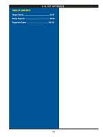
6.4l dit appendix
TABLE OF CONTENTS
Torque Charts ...................................................... 82-87
Wiring Diagram ................................................... 88-89
Diagnostic Codes .............................................. 90-101
82
special torque chart (reference only)
Note: All torque specs are ±10% unless stated otherwise.
COMPONENT STANDARD METRIC
Bedplate mounting bolts (crankcase bolts) Figure C Figure C
Camshaft follower guide bolt/washer 114 lbf/in 13 Nm
Camshaft position (CMP) sensor 114 lbf/in 13 Nm
Camshaft thrust plate mounting bolts 23 lbf/ft 31 Nm
Connecting rod bolt (Initial) 33 lbf/ft 45 Nm
Connecting rod bolt (Final) 50 lbf/ft 68 Nm
Coolant (block) heater 30 lbf/ft 41 Nm
Coolant pump mounting bolts 23 lbf/ft 31 Nm
Coolant pump pulley mounting bolts 23 lbf/ft 31 Nm
Crankcase breather to valve cover 114 lbf/in 13 Nm
Crankcase breather drain fitting to crankcase 18 lbf/ft 25 Nm
Crankcase breather tube clip bolt 23 lbf/ft 31 Nm
Crankcase coolant drain plug (M16) 180 lbf/in 20 Nm
Crankshaft position (CKP) sensor 114 lbf/in 13 Nm
Cylinder head bolts (only use new bolts, note 3) Figure A Figure A
EGR cooler inlet temperature sensor (EGRT Inlet) 32 lbf/ft 44 Nm
EGR coolant system hose clamps 31 lbf/in 3.5 Nm
EGR cooler outlet temperature sensor (EGRT Outlet) 28 lbf/ft 38 Nm
EGR DOC tube to RB up-tube bolts & nuts 23 lbf/ft 31 Nm
EGR DOC tube to EGR cooler horizontal bolts 23 lbf/ft 31 Nm
EGR cooler band clamps Figure K Figure K
EGR cooler vertical to EGR valve housing bolts 23 lbf/ft 31 Nm
EGR cooler vertical bracket mounting bolts 23 lbf/ft 31 Nm
EGR cooler horizontal to EGR cooler vertical flange 23 lbf/ft 31 Nm
EGR throttle body to EGR valve housing 88 lbf/in 10 Nm
EGR valve housing to intake manifold 88 lbf/in 10 Nm
EGR valve to EGR valve housing 88 lbf/in 10 Nm
Engine coolant temperature sensor (ECT) 159 lbf/in 18 Nm
Engine oil pressure switch (EOP) 124 lbf/in 14 Nm
Engine oil temperature sensor (EOT) 159 lbf/in 18 Nm
Exhaust backpressure (EP) connector to DOC tube 20 lbf/ft 27 Nm
Exhaust backpressure (EP) tube bracket nut 80 lbf/in 9 Nm
Exhaust backpressure (EP) tube nut to EP sensor 180 lbf/in 20 Nm
Exhaust backpressure (EP) tube nut to exhaust connector 180 lbf/in 20 Nm
Exhaust manifold flange studs 159 lbf/in 18 Nm
Exhaust manifold heat shield mounting bolts & nut 88 lbf/in 10 Nm
Exhaust manifold heat shield spacers to stud bolts 88 lbf/in 10 Nm
Exhaust manifold mounting bolts and stud bolts (note 4) Figure F Figure F
Exhaust up-tube to exhaust manifold nuts 23 lbf/ft 31 Nm
Exhaust up-tube to turbo bolts 18 lbf/ft 24 Nm
Flywheel/flexplate bolts (only use new bolts, note 3) Figure B Figure B
Front cover mounting bolts 23 lbf/ft 31 Nm
Fuel cooler reservoir mounting bolts 114 lbf/in 13 Nm
Fuel filter cap 20 lbf/ft 27 Nm
Fuel fitting banjo bolt with copper washer (M12) 28 lbf/ft 38 Nm
Fuel fitting banjo bolt with steel washer w/viton insert (M12) 18 lbf/ft 25 Nm
Fuel fitting banjo bolt (M14) 35 lbf/ft 47 Nm
Fuel injector hold down clamp bolts 28 lbf/ft 38 Nm
Fuel injector return tube nut to check valve 28 lbf/ft 38 Nm
Fuel return passage plug (rear of cylinder head) 20 lbf/ft 27 Nm
Fuel rail pressure sensor (FRP) Figure L Figure L
Fuel supply and return tube clamp to upper oil pan 23 lbf/ft 31 Nm
83
special torque chart (reference only)
STANDARD TORQUE CHART
Hex Flange Head
Thread Torque Torque Wrench
Diameter Nm Size (mm)
M6 x 1 114 lbf/in 13 8
M8 x 1.25 23 lbf/ft 31 10
M10 x 1.5 45 lbf/ft 62 13
M12 x 1.75 79 lbf/ft 107 15
M14 x 2 127 lbf/ft 172
M15 x 2 159 lbf/ft 216
M16 x 2 196 lbf/ft 266 21
Torque Chart Notes
1) Lightly coat o-ring with clean engine prior to install.
2) Apply threadlock 262 to bolt threads prior to install.
3) Do not reuse. These bolts are one time stretch to yield.
4) Do not reuse exhuast manifold bolts and studbolts.
COMPONENT STANDARD METRIC
Glow plug 124 lbf/in 14 Nm
Glow plug control module bolts and nuts (GPCM) 114 lbf/in 13 Nm
High pressure common rail (HPCR) mounting bolts 23 lbf/ft 31 Nm
High pressure common rail (HPCR) to fuel injector tubes Figure G, I Figure G, I
High pressure fuel injection pump & pump-to-rail tube installation Figure H Figure H
High pressure fuel injection pump cover mounting bolts 114 lbf/in 13 Nm
High pressure fuel injection pump drive gear bolt 57 lbf/ft 78 Nm
High pressure fuel injection pump mounting bolts 45 lbf/ft 62 Nm
High pressure fuel tube nuts (all) 144 lbf/in 30 Nm
Intake manifold pressure sensor (MAP) 106 lbf/in 12 Nm
Intake air temperature 2 (IAT2) sensor 124 lbf/in 14 Nm
Intake manifold bolts and stud bolts Figure D Figure D
Lifting eye bolts 45 lbf/ft 62 Nm
Oil cooler to crankcase mounting bolts (M8) 23 lbf/ft 31 Nm
Oil filter base to cooler cover screws (M6 thread forming) 89 lbf/in 10 Nm
Oil filter cap 18 lbf/ft 25 Nm
Oil filter housing to filter base bolts 16 lbf/ft 22 Nm
Oil filter stand pipe bolt (M5 thread forming) W/new oil cooler 61 lbf/in 7 Nm
Oil filter stand pipe bolt (M5 thread forming) reusing existing oil cooler 30 lbf/in 3 Nm
Oil pan bolt - lower pan 114 lbf/in 13 Nm
Oil pan bolt - upper pan 114 lbf/in 13 Nm
Oil pan drain plug (see note 1) 32 lbf/ft 44 Nm
Oil pickup tube bolts 114 lbf/in 13 Nm
Oil pump housing bolts 16 lbf/ft 22 Nm
Oil pressure regulator plug 26 lbf/ft 35 Nm
Piston cooling jet mounting bolts (see note 2) 114 lbf/in 13 Nm
Rocker arm assembly bolts Figure J Figure J
Rear cover M10 (manual only) 45 lbf/ft 62 Nm
Rear cover M8 (man & auto) 23 lbf/ft 31 Nm
Thermostat housing hold down plate bolts 114 lbf/in 13 Nm
Turbocharger actuator mounting bolt 168 lbf/in 19 Nm
Turbocharger air inlet duct clamp 44lbf/in 5 Nm
Turbocharger pedestal bolts 45 lbf/ft 62 Nm
Turbocharger to pedestal bolts 148 lbf/ft 201 Nm
Turbocharger crossover tube support mounting 79 lbf/in 9 Nm
Turbocharger heat shield bolts 96 lbf/in 11 Nm
Turbocharger oil supply banjo bolts (M12) 28 lbf/ft 38 Nm
Turbocharger oil supply standoff fittings to center housings 35 lbf/ft 47 Nm
Turbocharger oil supply tube retaining bolt to oil cooler 114 lbf/in 13 Nm
Valve cover base bolts 114 lbf/in 13 Nm
Valve cover bolts and studs 80 lbf/in 9 Nm
Vibration damper bolts (note 3) (only use new bolts) Figure E Figure E
84
special torque chart (reference only)
FIGURE B: Flywheel Bolts
Step 1: Torque the bolts to 44 lbf/in (5 Nm) in
the numerical sequence shown.
Step 2: Torque the bolts to 69 lbf/ft (94 Nm) in the
numerical sequence shown above.
Note: Flywheel bolts may not be reused once torqued.
FIGURE C: Bedplate Bolts (main bearing bolts)
Step 1: Torque the bolts to 110 lbf/ft (149 Nm)
in the numerical sequence shown.
Step 2: Torque the bolts to 130 lbf/ft (176 Nm)
in the numerical sequence shown.
Step 3: Torque the bolts to 170 lbf/ft (231 Nm)
in the numerical sequence shown.
FIGURE A: Cylinder Head Bolts
Step 1: Lightly lubricate M16 head bolt threads and washer
faces with clean engine oil prior to assembly.
Step 2: Torque M16 head bolts (labeled 1-10) to 70
lb/ft (95 Nm) in numerrical sequence shown.
Step 3: Back out M16 head bolts and retorque to 115 lb/ft
(156 Nm) one at a time in numerical sequence shown.
Step 4: Tighten M16 head bolts and additional 90
degrees in numerical sequence shown.
Step 5: Tighten M16 head bolts an additional 90 degrees
(2nd time) in numerical sequence shown.
Step 6: Torque M8 head bolts (labeled 11-15) to 18
lb/ft (24 Nm) in numerical sequence shown.
Step 7: Torque M8 head bolts to 23 lb/ft (31 Nm)
in numerical sequence shown.
Note: Head bolts may not be reused once torqued.
Note: If bolt chatter occurs during step
4, repeat step 3 and continue.
85
special torque chart (reference only)
FIGURE D: Intake Manifold Bolts
Step 1: Loosely install all bolts in the
numerical sequence shown.
Step 2: Torque bolts to 100 lb/in (11Nm) in
the numerical sequence shown.
Note: Bolt locations with double circles represent stud bolts.
FIGURE E: Vibration Damper Bolts
Step 1: Torque each bolt to 50 lb/ft (68 Nm) in
the numerical sequence shown.
Step 2: Tighten each bolt 90 degrees clockwise
in the numerical sequence shown.
Note: Damper bolts may not be reused once torqued.
FIGURE F: Exhaust Manifold Bolts
Step 1: Torque bolts to 18 lb/ft (25Nm) in the
numerical sequence shown.
Step 2: Repeat the sequence using the same torque.
Note: Exhaust manifold bolts and studbolts
may not be reused once torqued.
86
special torque chart (reference only)
FIGURE H: High Pressure Pump and Pump-to-Rail HP Tubes Installation Procedure
Step 1: Install and final torque the high pressure fuel injetion pump to 45 lb/ft (61 Nm).
Step 2: Install the pump cover gasket and make electrical connections between the pump and gasket. Install the pump cover and fasten the bolts.
Step 3: Remove the four plastic caps covering the supply, return, and high pressure rail connectors.
Step 4: Obtain left and right “pump-to-rail” high pressure tubes from the packaging.
Step 5: Position the high pressure tubes between the pump and the rails and fully hand start and seat the tube
nuts onto the mating pump and rails high pressure connections.
Note: Support the tubes while hand snugging the nuts to assure proper assembly of the joints.
Step 6: Snug the tube nuts to 1.5 lb/ft (2 Nm).
Step 7: Torque the pump and rail tube nuts to 106 lb/in (12 Nm +2 / -0).
Step 8: Place a visible mark with a permanent marker on the tube nut and the high pressure fuel rail and the high pressure
fuel injection pump threaded connection. Turn the tube nuts one flat of the nut which is equal to 60 degrees.
FIGURE I: Injector-Pipe-Rail Sub-Assembly Process
Step 1: Place the fuel injectors w/clamps in the head and snug the bolts.
Step 2: Place and snug the fuel rail (leave one thread loose).
Step 3: Place four fuel jumper tubes to injector/fuel rail and start 1-2 threads.
Step 4: Snug injector side tube nuts to 1.5 lb/ft (2 Nm). (Special torque sequence is used, see note below).
Step 5: Snug fuel rail side tube nuts to 1.5 lb/ft (2 Nm). (Special torque sequence is used, see note below).
Step 6: Final torque the fuel rail mounting bolts.
Step 7: Final torque the injector bolts. (Special torque sequence is used, see note below).
Step 8: Final torque the injector side tube nuts to 106 lb/in (12 Nm +2 / -0). (Special torque sequence is used, see note below).
Step 9: Final torque the fuel rail side tube nuts to 106 lb/in (12 Nm +2 / -0). (Special torque sequence is used, see note below).
Step 10: Place a visible mark with a permanent marker on the tube nut and the fuel injector threaded connection. Turn the tube
nuts one flat of the nut which is equal to 60 degrees. (Special torque sequence is used, see note below).
Step 11: Place a visible mark with a permanent marker on the tube nut and the high pressure fuel rail threaded connection. Turn
the tube nuts one flat of the nut which is equal to 60 degrees. (Special torque sequence is used, see note below).
NOTE: Torque the components in the center two cylinders first, then torque the components in the outer two cylinders last.
FIGURE G: HPCR Fuel Components Assembly Procedure
Hand start and hand snug tube nuts.
Step 1: Install injectors, clamps and bolts and hand start the clamp bolts.
Step 2: Rundown the injector clamp bolts to a torque of 1.5 lb/ft (2 Nm). Injectors will seat while torquing the bolts.
Note: The injectors must be fully seated and snugged, but moveable for high pressure connector and HP tube alignment.
Step 3: Install the HP rail and hand start two rail mounting bolts.
Note: Rail must be moveable, but not loose.
Step 4: Remove the four plastic caps from the rail high pressure connectors (HPC’s) and four plastic caps from the injector HPC’s.
Step 5: Obtain four “rail to injector” jumper tubes from the packaging.
Step 6: Position the four (one at a time) between the rail and injectors and fully hand start and seat the tube nuts onto
the mating rail and injector HPC’s. Snug the rail and injector tube nuts using the inside-out step sequence
(i.e. two inside nuts then two outside nuts) with a tube nut click wrench set to 1.5 lb/ft (2 Nm).
Step 7: Final torque the injector clamp bolts to 28 lb/ft (38 Nm).
Step 8: Final torque the two M8 rail bolts to 23 lb/ft (31 Nm).
Step 9: Torque the rail and injector tube nuts to 106 lb/in (12 Nm +2 / -0).
Step 10: Place a visible mark with a permanent marker on the tube nut and the high pressure fuel rail and fuel injector
threaded connection. Turn the tube nuts one flat of the nut which is equal to 60 degrees.
87
special torque chart (reference only)
FIGURE J: Fulcrum Plate / Rocker Arm Support Assembly
Step 1: Position crankshaft at approximate #1 & #4 cylinder TDC by observing damper dowel pin and
clocking it to the 10:30 position (as viewed from the front of the engine)
Step 2: Determine which cylinder is actually in the firing position by installing pushrods, and observing #3 intake and #8 intake.
Step 3: If #3 intake pushrod shows cam lift, this is the #1 firing position. Torque only fulcrum plates #1,2,7,8 per steps 4-6.
If #8 intake pushrod shows cam lift, this is the #4 firing position. Torque only fulcrum plates #3,4,5,6 per steps 4-6.
Step 4: Partially run down both M10 bolts until they just contact the fulcrum plate.
Step 5: Fully run down and torque inboard (upper) bolt to 45 lb/ft (62 Nm).
Step 6: Fully run down and torque outboard (lower) bolt to 45 lb/ft (62 Nm).
Step 7: Rotate crankshafft 360 degrees to position it at the alternate cylinder TDC (dowel pin at 10:30 position).
Step 8: Identify remaining group of fulcrum plates per step 3, and torque per steps 4-6.
FIGURE K: EGR Cooler Mounting Clamps
Horizontal Cooler
Step 1: Pre-torque EGR clamps to 88lb/in (10 Nm).
Step 2: Loosen clamp nuts two full turns.
Step 3: Final torque to 69 lb/in (8 Nm)
Vertical Cooler
Step 1: Pre-torque EGR clamps to 75 lb/in (8.5 Nm).
Step 2: Loosen clamp nuts two full turns.
Step 3: Final torque to 57 lb/in (6.5 Nm).
FIGURE L: Fuel Rail Pressure Sensor (FRP)
Step 1: Snug the sensor hand tight to 1.5 lb/ft (2 Nm)
Step 2: Place a visible mark with a permanent marker on the sensor and the high pressure fuel rail connection.
Turn the sensor one flat of the sensor base which is equal to 60 degrees.
88
wiring diagram (single alt.) reference only
Refer to Ford Wiring Diagrams for Wiring