Automobile training 28 SRS
Bạn đang xem bản rút gọn của tài liệu. Xem và tải ngay bản đầy đủ của tài liệu tại đây (13.66 MB, 526 trang )
SUPPLEMENTAL RESTRAINT SYSTEM – AIRBAG SYSTEM
RS–1
AIRBAG SYSTEM
PRECAUTION
CAUTION:
• The vehicle is equipped with a Supplemental Restraint
System (SRS), which consists of a driver airbag, front
passenger airbag, side airbags, curtain shield airbags
and front seat belt pretensioners. Failure to carry out
service operations in the correct sequence could
cause the SRS to unexpectedly deploy during
servicing, possibly leading to a serious accident.
Furthermore, if a mistake is made in servicing the
SRS, it is possible that the SRS may fail to operate
when required. Before performing servicing (including
removal or installation of parts, inspection or
replacement), be sure to read the following items
carefully, then follow the correct procedures as
indicated in the repair manual.
• Wait at least 90 seconds after the ignition switch is
turned off and the negative (-) terminal cable is
disconnected from the battery before starting the
operation.
(The SRS is equipped with a back-up power source, so
if work is started within 90 seconds of disconnecting
the negative (-) terminal cable of the battery, the SRS
may be deployed).
• Do not directly expose the steering pad, front
passenger airbag assembly, center airbag sensor
assembly, front airbag sensor, front seat inner belt
assembly, seat position sensor, occupant
classification ECU, front seat side airbag assembly,
side airbag sensor, curtain shield airbag assembly,
rear airbag sensor or front seat outer belt assembly to
hot air or flames.
NOTICE:
• Malfunction symptoms of the SRS are difficult to
confirm, so DTCs are the most important source of
information when troubleshooting. When
troubleshooting the SRS, always inspect DTCs before
disconnecting the battery.
• Even in the case of a minor collision when the SRS
does not deploy, the following parts should be
inspected.
– Steering pad
– Front passenger airbag assembly
– Center airbag sensor assembly
– Front airbag sensor
– Front seat inner belt assembly
– Seat position sensor
– Occupant classification ECU
– Front seat side airbag assembly
– Side airbag sensor
– Curtain shield airbag assembly
– Rear airbag sensor
RS
RS–2
RS
SUPPLEMENTAL RESTRAINT SYSTEM – AIRBAG SYSTEM
– Front seat outer belt assembly
• Before commencing repair work, remove the airbag
sensor if any kind of shock is likely to occur to the
airbag sensor during the operation.
• Never use SRS parts from another vehicle. When
replacing parts, replace them with new ones.
• Never disassemble or repair any of the following parts
in order to reuse them. If any of these parts have been
dropped, or a defect is found (e.g. cracks, dents or any
other defects) in any of the housings, brackets or
connectors, then replace the part with a new one.
– Steering pad
– Front passenger airbag assembly
– Center airbag sensor assembly
– Front airbag sensor
– Front seat inner belt assembly
– Seat position sensor
– Occupant classification ECU
– Front seat side airbag assembly
– Side airbag sensor
– Curtain shield airbag assembly
– Rear airbag sensor
– Front seat outer belt assembly
• Use a volt/ohmmeter with high impedance (10 kΩ/V
minimum) for troubleshooting the electrical circuits.
• Information labels are attached to the periphery of the
SRS components. Follow the instructions in the
cautions.
• After work on the SRS is completed, perform the SRS
warning light check (See page RS-31).
• When the negative (-) terminal cable is disconnected
from the battery, the memory will be cleared.
Therefore make a record of the contents stored in
each system before starting work. When the work is
finished, reset each system as it was before. Never
use a back-up power supply from outside the vehicle
to avoid erasing the memory in any system.
• If the vehicle is equipped with a mobile
communication system, refer to the precautions in the
INTRODUCTION section.
HINT:
In the airbag system, the center airbag sensor assembly, front
airbag sensor LH and RH, side airbag sensor LH and RH,
rear airbag sensor LH and RH are collectively referred to as
the airbag sensors.
1. HANDLING PRECAUTIONS FOR AIRBAG SENSORS
(a) Before starting the following operations, wait for at
least 90 seconds after disconnecting the negative () terminal cable from the battery:
(1) Replacement of the airbag sensors
(2) Adjustment of the front/rear doors of the vehicle
equipped with the side airbags and curtain shield
airbags (fitting adjustment)
SUPPLEMENTAL RESTRAINT SYSTEM – AIRBAG SYSTEM
2.
RS–3
(b) When connecting or disconnecting the airbag
sensor connectors, ensure that each sensor is
installed in the vehicle.
(c) Do not use the airbag sensors which have been
dropped during the operation or transportation.
(d) Do not disassemble the airbag sensors.
INSPECTION PROCEDURE FOR VEHICLE INVOLVED
IN ACCIDENT
(a) When the airbag has not deployed, confirm the
DTCs by checking the SRS warning light. If there is
any malfunction in the SRS airbag system, perform
troubleshooting.
(b) When any of the airbags have deployed, replace the
airbag sensors and check the installation condition.
RS
RS–4
SUPPLEMENTAL RESTRAINT SYSTEM – AIRBAG SYSTEM
3.
SRS CONNECTORS
(a) SRS connectors are located as shown in the
following illustration.
RS
Passenger Airbag ON/OFF Indicator
11
12
Front Airbag Sensor LH
9
10
Steering Pad (Driver Side Squib)
5
Spiral Cable
To Other Side
20
6
Front Passenger Airbag Assembly
(Front Passenger Side Squib)
19
7
21
22
8
Front Airbag Sensor RH
9
10
Combination Meter
2
1
4
3
4
3
13
14
Center Airbag Sensor Assembly
ECM
15
16
Main Boby ECU
17
18
H100937E02
SUPPLEMENTAL RESTRAINT SYSTEM – AIRBAG SYSTEM
RS–5
33 Seat Position Sensor
RS
34
31 Front Seat Inner Belt Assembly LH
32
29 Side Airbag Sensor LH (*1)
30
27 Curtain Shield Airbag Assembly LH
(Driver Side Curtain Shield Squib) (*1)
28
25 Front Seat Side Airbag Assembly LH
(Side Squib LH) (*1)
26
To Other Side
23
Front Seat Outer Belt Assembly LH
(Front Pretensioner Squib LH)
24
23
Front Seat Outer Belt Assembly RH
(Front Pretensioner Squib RH)
24
25 Front Seat Side Airbag Assembly RH
(Side Squib RH) (*1)
2
1
4
3
4
3
26
27 Curtain Shield Airbag Assembly RH
(Curtain Shield Squib RH) (*1)
Center Airbag Sensor Assembly
28
29 Side Airbag Sensor RH (*1)
30
35 Occupant Classification ECU
36
*1: w/ Side Airbag Assembly and Curtain Shield Airbag Assembly
H100938E02
RS–6
RS
SUPPLEMENTAL RESTRAINT SYSTEM – AIRBAG SYSTEM
No.
Item
Application
(1)
Terminal Twin-Lock Mechanism
Connectors 2, 4, 9, 11, 13, 15, 19, 21, 22, 25, 29, 31, 33
(2)
Activation Prevention Mechanism
Connectors 2, 4, 6, 8, 20, 22, 24, 26, 28
(3)
Half Connection Prevention Mechanism
Connectors 9, 19, 21, 26, 29
(4)
Connector Position Assurance Mechanism
Connector 9
(5)
Connector Lock Mechanism (1)
Connectors 5, 7, 23, 27
(6)
Connector Lock Mechanism (2)
Connectors 2, 4
(7)
Improper Connection Prevention Lock Mechanism
Connectors 1, 3
Spacer
Housing
H045308E01
(b) All connectors in the SRS except the seat position
sensor connector and the occupant classification
ECU connector are colored yellow to distinguish
them from other connectors. Some connectors have
special functions, and are specially designed for the
SRS. These connectors use durable gold-plated
terminals, and are placed in the locations shown on
the previous page to ensure high reliability.
(1) Terminal twin-lock mechanism:
Each connector is a two-piece component
consisting of a housing and a spacer. This
design enables the terminal to be locked
securely by two locking devices (the retainer and
the lance) to prevent the terminals from
becoming disconnected.
RS–7
SUPPLEMENTAL RESTRAINT SYSTEM – AIRBAG SYSTEM
(2) Activation prevention mechanism:
Each connector contains a short spring plate.
When the connector is disconnected, the short
spring plate creates a short circuit by
automatically connecting the positive (+) and
negative (-) terminals of the squib.
When Connector is Connected
When Connector is Disconnected
Short Spring Plate
Short Spring Plate
Housing
Terminal
Contacting Male Terminal
Housing
Squib
Squib
Closed Circuit
Connectors
Short Spring Plate ON
Short Spring Plate
C127724E01
(3) Half connection prevention mechanism:
If the connector is not completely connected, the
connector is disconnected by the spring
operation so that no continuity exists.
Stopper
Locking Arm
Slider
Spring
Stopper
Locking Part
Rebounded by Slider (Spring)
H101827E01
RS
RS–8
SUPPLEMENTAL RESTRAINT SYSTEM – AIRBAG SYSTEM
(4) Connector position assurance mechanism:
The CPA (yellow part) slides, which completes
the connector engagement, only when the
housing lock (white part) is completely engaged.
RS
Housing Lock (White Part)
CPA (Yellow Part)
H101954E01
(5) Connector lock mechanism (1):
Locking the connector lock button connects the
connector.
Lock Button
Claw
Groove
H101828E01
(6) Connector lock mechanism (2):
Both the primary lock with holder lances and the
secondary lock with a retainer prevent the
connectors from becoming disconnected.
Holder
Lance
Retainer
Holder
Retainer
Retainer
C101082E02
RS–9
SUPPLEMENTAL RESTRAINT SYSTEM – AIRBAG SYSTEM
(7) Improper connection prevention lock
mechanism:
When connecting the holder, the lever is pushed
into the end by rotating around the A axis to lock
the holder securely.
RS
A
A
Lever
1
2
H101830E01
4.
DISCONNECTION OF CONNECTORS FOR
STEERING PAD, FRONT PASSENGER AIRBAG
ASSEMBLY (SQUIB SIDE), CURTAIN SHIELD
AIRBAG ASSEMBLY AND FRONT SEAT OUTER
BELT ASSEMBLY
HINT:
Tape up the screwdriver tip before use.
(a) Release the lock button (yellow part) of the
connector using a screwdriver.
RS–10
SUPPLEMENTAL RESTRAINT SYSTEM – AIRBAG SYSTEM
(b) Insert the screwdriver tip between the connector
and the base, and then raise the connector.
(a)
RS
Lock Button
(Yellow Part)
(b)
Lock Button
(Yellow Part)
H101832E01
Y
5.
CONNECTION OF CONNECTORS FOR STEERING
PAD, FRONT PASSENGER AIRBAG ASSEMBLY
(SQUIB SIDE), CURTAIN SHIELD AIRBAG
ASSEMBLY AND FRONT SEAT OUTER BELT
ASSEMBLY
(a) Connect the connector.
SUPPLEMENTAL RESTRAINT SYSTEM – AIRBAG SYSTEM
RS–11
(b) Push the lock button (yellow part) of the connector
down securely. (When locking, a click sound can be
heard.)
RS
Lock Button
(Yellow Part)
H101833E01
Y
6.
Slider
DISCONNECTION OF CONNECTORS FOR FRONT
PASSENGER AIRBAG ASSEMBLY (INSTRUMENT
PANEL WIRE SIDE)
(a) Place a finger on the slider, slide the slider to
release the lock, and then disconnect the connector.
Slider
Disconnection complete
H101836E01
RS–12
SUPPLEMENTAL RESTRAINT SYSTEM – AIRBAG SYSTEM
7.
RS
Slider
CONNECTION OF CONNECTORS FOR FRONT
PASSENGER AIRBAG ASSEMBLY (INSTRUMENT
PANEL WIRE SIDE)
(a) Connect the connector as shown in the illustration.
(When locking, make sure that the slider returns to
its original position and a click sound can be heard.)
HINT:
When connecting, the slider sides. Do not touch the
slider while connecting, as this may result in an
insecure fit.
Slider
Connection complete
H101837E01
SUPPLEMENTAL RESTRAINT SYSTEM – AIRBAG SYSTEM
8.
RS–13
DISCONNECTION OF CONNECTORS FOR FRONT
SEAT SIDE AIRBAG ASSEMBLY AND REAR SEAT
AIRBAG ASSEMBLY
(a) Place a finger on the slider, slide the slider to
release the lock, and then disconnect the connector.
RS
Slider
Slider
Disconnection complete
H101834E01
9.
CONNECTION OF CONNECTORS FOR FRONT SEAT
SIDE AIRBAG ASSEMBLY AND REAR SEAT AIRBAG
ASSEMBLY
(a) Connect the connector as shown in the illustration.
(When locking, make sure that the slider returns to
its original position and a click sound can be heard.)
HINT:
When connecting, the slider slides. Do not touch the
slider while connecting, as this may result in an
insecure fit.
RS–14
RS
SUPPLEMENTAL RESTRAINT SYSTEM – AIRBAG SYSTEM
Slider
Slider
Connection complete
H101835E01
10. DISCONNECTION OF CONNECTORS FOR CENTER
AIRBAG SENSOR ASSEMBLY
(a) Pull the lever by pushing part A as shown in the
illustration and disconnect the holder (with
connectors).
Holder (with connectors)
A
Disconnection complete
H100822E02
HINT:
Perform the following procedures when replacing
the holder.
SUPPLEMENTAL RESTRAINT SYSTEM – AIRBAG SYSTEM
RS–15
(b) Remove the holder.
(1) Using a screwdriver, unlock the retainer.
RS
Retainer
H100823E01
(2) Release the fitting lances and remove the
holder.
Lances
H100824E01
H100825
(c) Install the holder.
(1) Install the connectors into the holder. (When
locking, a click sound can be heard.)
HINT:
The retainer is locked when the holder is
connected.
11. CONNECTION OF CONNECTORS FOR CENTER
AIRBAG SENSOR ASSEMBLY
(a) Firmly insert the holder (with connectors) into the
center airbag sensor assembly until it cannot be
pushed any further.
RS–16
SUPPLEMENTAL RESTRAINT SYSTEM – AIRBAG SYSTEM
(b) Push the lever to connect the holder (with
connectors). (When locking, a click sound can be
heard.)
HINT:
The holder slides into the center airbag sensor
assembly when it is being connected. Do not hold
the holder while connecting, as it may result in an
insecure fit.
RS
Holder (with connectors)
Lever
Connection is complete
H100903E01
12. DISCONNECTION OF CONNECTORS FOR FRONT
AIRBAG SENSOR
(a) Push down the housing lock (white part) and slide
the CPA (yellow part). (At this time, the connector
cannot be disconnected yet.)
(b) Push down the housing lock (white part) again and
disconnect the connector.
HINT:
Do not push down part A shown in the illustration
when disconnecting.
SUPPLEMENTAL RESTRAINT SYSTEM – AIRBAG SYSTEM
RS–17
A
Housing Lock (White Part)
Connector
lock is
released
RS
CPA (Yellow Part)
H101952E01
(c) After disconnecting the connector, check that the
position of the housing lock (white part) is as shown
in the illustration.
H101953
RS–18
SUPPLEMENTAL RESTRAINT SYSTEM – AIRBAG SYSTEM
13. CONNECTION OF CONNECTORS FOR FRONT
AIRBAG SENSOR
(a) Before connecting the connectors, check that the
position of the housing lock (white part) is as shown
in the illustration.
RS
H101950
(b) Be sure to engage the connectors until they are
locked. (When locking, make sure that a click sound
can be heard.)
HINT:
When connecting them, the housing lock (white
part) slides. Do not hold the housing lock (white
part) and part A, as it may result in an insecure fit.
A
Housing Lock (White Part)
CPA (Yellow Part)
Connection is complete
H101951E01
SUPPLEMENTAL RESTRAINT SYSTEM – AIRBAG SYSTEM
Outer
H100826E01
RS–19
14. DISCONNECTION OF CONNECTORS FOR SIDE
AIRBAG SENSOR AND REAR AIRBAG SENSOR
(a) While holding both sides of the outer connector
locking sleeve, slide the outer in the direction shown
by the arrow.
(b) When the connector lock is released, the
connectors are disconnected.
HINT:
Be sure to hold both outer flanks. Holding the top
and bottom sides will make disconnection difficult.
Connector lock is released
Disconnection is complete
H100827E01
15. CONNECTION OF CONNECTORS FOR SIDE AIRBAG
SENSOR AND REAR AIRBAG SENSOR
(a) Connect the connector as shown in the illustration.
(When locking, make sure that the outer returns to
its original position and a click sound can be heard)
HINT:
When connecting, the outer slides. Do not hold the
outer while connecting, as it may result in an
insecure fit.
Outer
Outer
Connection is complete
H100828E02
RS
RS–20
SUPPLEMENTAL RESTRAINT SYSTEM – AIRBAG SYSTEM
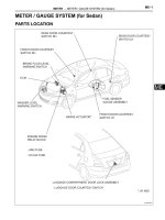
PARTS LOCATION
HATCHBACK:
RS
COMBINATION METER
w/o Tachometer:
w/ Tachometer:
SRS WARNING LIGHT
SRS WARNING LIGHT
FRONT PASSENGER SEAT
BELT WARNING LIGHT
FRONT AIRBAG SENSOR RH
FRONT PASSENGER
AIRBAG ASSEMBLY
SPIRAL CABLE
ECM
STEERING PAD
DLC3
CENTER AIRBAG
SENSOR ASSEMBLY
Passenger Airbag ON/OFF Indicator
FRONT AIRBAG SENSOR LH
H100912E02
RS–21
SUPPLEMENTAL RESTRAINT SYSTEM – AIRBAG SYSTEM
HATCHBACK:
RS
FRONT SEAT SIDE AIRBAG
ASSEMBLY RH (*1)
CURTAIN SHIELD AIRBAG
ASSEMBLY LH (*1)
CURTAIN SHIELD AIRBAG
ASSEMBLY RH (*1)
REAR AIRBAG
SENSOR RH (*1)
SIDE AIRBAG
SENSOR LH (*1)
FRONT SEAT OUTER
BELT ASSEMBLY LH
SIDE AIRBAG
SENSOR RH (*1)
FRONT SEAT SIDE AIRBAG
ASSEMBLY LH (*1)
FRONT SEAT OUTER
BELT ASSEMBLY RH
SEAT POSITION SENSOR
REAR AIRBAG
SENSOR LH (*1)
OCCUPANT CLASSIFICATION ECU
FRONT SEAT INNER BELT ASSEMBLY LH
*1: w/ Side Airbag Assembly and Curtain Shield Airbag Assembly
C141225E01
RS–22
SUPPLEMENTAL RESTRAINT SYSTEM – AIRBAG SYSTEM
SEDAN:
COMBINATION METER
RS
w/o Tachometer:
w/ Tachometer:
SRS WARNING LIGHT
SRS WARNING LIGHT
FRONT PASSENGER
AIRBAG ASSEMBLY
FRONT AIRBAG SENSOR RH
SPIRAL CABLE
FRONT AIRBAG
SENSOR LH
ECM
FRONT PASSENGER
SEAT BELT
WARNING LIGHT
DLC3
STEERING PAD
Passenger Airbag ON/OFF Indicator
CENTER AIRBAG
SENSOR ASSEMBLY
H102139E01
SUPPLEMENTAL RESTRAINT SYSTEM – AIRBAG SYSTEM
RS–23
SEDAN:
FRONT SEAT SIDE AIRBAG
ASSEMBLY RH (*1)
CURTAIN SHIELD AIRBAG
ASSEMBLY RH (*1)
CURTAIN SHIELD AIRBAG
ASSEMBLY LH (*1)
REAR AIRBAG
SENSOR RH (*1)
SIDE AIRBAG
SENSOR LH (*1)
FRONT SEAT OUTER
BELT ASSEMBLY LH
SIDE AIRBAG
SENSOR RH (*1)
FRONT SEAT
SIDE AIRBAG
ASSEMBLY LH (*1)
FRONT SEAT OUTER
BELT ASSEMBLY RH
SEAT POSITION
SENSOR
REAR AIRBAG
SENSOR LH (*1)
OCCUPANT CLASSIFICATION ECU
FRONT SEAT INNER
BELT ASSEMBLY LH
*1: w/ Side Airbag Assenmbly and Curtain Shield Airbag Assembly
C141226E02
RS
RS–24
SUPPLEMENTAL RESTRAINT SYSTEM – AIRBAG SYSTEM
SYSTEM DIAGRAM
Front Airbag Sensor LH
Steering Pad (Driver Side Squib)
Front Airbag Sensor RH
Front Passenger Airbag Assembly
(Front Passenger Side Squib)
RS
Side Airbag Sensor LH *1
Front Seat Side Airbag Assembly LH
(Side Squib LH) *1
Side Airbag Sensor RH *1
Front Seat Side Airbag Assembly RH
(Side Squib RH) *1
Rear Airbag Sensor LH *1
Rear Airbag Sensor RH *1
Front Seat Inner Belt Assembly LH
Front Seat Outer Belt Assembly LH
(Driver Side Pretensioner Squib)
Center Airbag
Sensor
Assembly
Front Seat Outer Belt Assembly RH
(Front Pretensioner Squib RH)
Seat Position Sensor
Occupant Classification ECU
Curtain Shield Airbag Assembly LH
(Driver Side Curtain Shield Squib) *1
Curtain Shield Airbag Assembly RH
( Curtain Shield Squib RH) *1
: CAN
*1: w/ Side Airbag Assembly and
Curtain Shield Airbag Assembly
Passenger Airbag ON/OFF Indicator
ECM
Combination Meter
Main Body ECU
H100904E02
SUPPLEMENTAL RESTRAINT SYSTEM – AIRBAG SYSTEM
RS–25
SYSTEM DESCRIPTION
1.
GENERAL
(a) Airbag for Frontal Collision
(1) The dual-stage SRS driver and front passenger
airbags deploy simultaneously in the event of a
frontal impact collision as supplements to the
seat belts. The dual-stage SRS airbag system
controls the airbag inflation output by judging the
extent of the impact, the seat position and
whether the seat belt is fastened.
Front Airbag Sensor
(RH or LH)
Driver Side Front
Seat Outer Belt
Impact
Collision
Seat Belt Buckle Switch
Streering Pad
Center Airbag
Sensor Assembly
Seat Position Sensor
Front Passenger Airbag
Combination Meter
(SRS Warning Light)
Front Passenger Side
Front Seat Outer Belt
ECM
CAN
Seat Belt Buckle Switch
Occupant Classification
ECU
H101935E01
RS