Windows Server 2003 Clustering & Load Balancing PHẦN 3 ppt
Bạn đang xem bản rút gọn của tài liệu. Xem và tải ngay bản đầy đủ của tài liệu tại đây (742.6 KB, 41 trang )
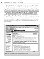
Microsoft pledges it won’t send any information on your drive to Microsoft itself,
and it archives your system to find what you do or don’t have. This is done rather
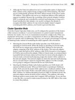
quickly. You’re then asked what you want to install from here and, as you can see in
Figure 2-1, Service Pack 2 for Windows 2000 is a selectable option. This is a quick way
to get the most updated software available from Microsoft and it takes all the guesswork
out of it. You can customize Windows Update to download and install only what you
want installed by selecting specific components, hot fixes, or entire service packs.
The site will scan your machine for what you need to install and give you the
options on what to install on your system. At press time, you want to install Service
Pack 3 and all post-Service Pack 3 hot fixes on your system.
Once you complete your Service Pack install, make sure your entire hardware install
is also current with the latest revisions or service packs on software and firmware on
your SCSI cards or BIOS. If an update is needed, now is the time to do it. Remember,
it’s better to do all this now, rather than when your system is in production and you
have to down it.
64 Windows Server 2003 Clustering & Load Balancing
OsbNetw / Windows Server 2003 Clustering & Load Balancing / Shimonski/ 222622-6 / Chapter 2
Figure 2-1. Selecting Service Pack 2 to be installed on your server
P:\010Comp\OsbNetw\622-6\ch02.vp
Monday, March 24, 2003 9:57:39 AM
Color profile: Generic CMYK printer profile
Composite Default screen
Although Chapter 1 explained that having a cluster makes it easier to down and
repair a production system, that doesn’t mean you want to be put in that position. A
Systems Administrator might not be at his happiest if he gets called in the middle of
the night to fix a system that crashed. Do all your testing and checking now before you
have users connected to the production system. Unforeseeable issues always pop up
here and there, but keeping them to a bare minimum is always something you should
strive for.
Now, once all packs and fixes are in, boot up clean and make sure you aren’t getting
any errors. When I say errors, I mean anything visible from the start of the boot process
to the end. You might have a problem with Windows Advanced Server itself, where
you get a Service Control Manager error pop-up. If you do get any errors while booted
into Windows, you should immediately check the Event Viewer. (I recommend checking
it anyway, whether or not you get errors, for good measure.) You can get to the Event
Viewer by opening the Computer Management console in the Administrative Tools
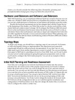
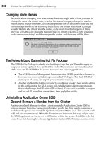
folder within your Start menu programs. In Figure 2-2, you can see the Computer
Management console with the Event Viewer. In the Details pane of the console,
a potential problem exists with the Dynamic Host Configuration Protocol (DHCP)
service, so flag that and check it before moving on to the next steps of the configuration.
To select an error event, simply double-click it.
Chapter 2: Designing a Clustered Solution with Windows 2000 Advanced Server 65
OsbNetw / Windows Server 2003 Clustering & Load Balancing / Shimonski/ 222622-6 / Chapter 2
Figure 2-2. Using the Event Viewer to troubleshoot your server
P:\010Comp\OsbNetw\622-6\ch02.vp
Monday, March 24, 2003 9:57:39 AM
Color profile: Generic CMYK printer profile
Composite Default screen
Once I open the event (in the following illustration), I can see what the problem is
and it isn’t a real problem at all. Because I haven’t yet configured my IP addresses on
my NIC cards, Windows 2000 Advanced Server was kind enough to notice this and
assign an IP address from the Automatic Private IP Addressing (APIPA) range, so
it can try to communicate with other nodes on the local subnet. This error will be
meaningless once we configure TCP/IP correctly later in the chapter, but it’s important
for you to look at potential problems you might be having. You can also see browser
errors on the Event Viewer System log, which we’ll address in the “NetBIOS and
WINS” section of this chapter.
Other places you can check in Windows 2000 Advanced Server for a quick visual of
your status are in the system applet’s control panel located in the Device Manager. You
can also find this in the Computer Management MMC console. By opening the console,
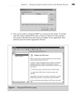
you can verify if you have a problem with your system’s hardware by reviewing the
visual icons, as seen in Figure 2-3.
If you see a large red X (shown in Figure 2-3) on a piece of hardware, this means it
was disabled by the system. The hardware could have created a problem serious enough
to warrant its operational removal, or you might have disabled it. Either way, you can
check here to make certain. If you see a yellow exclamation point or a yellow question
mark, you might need to reinstall drivers or you could have unknown hardware in
your system. Make sure you clean up all this before continuing.
If you use antivirus software, install that now. Check to make sure it’s installed
properly and that you downloaded and installed the most current virus definitions.
66 Windows Server 2003 Clustering & Load Balancing
OsbNetw / Windows Server 2003 Clustering & Load Balancing / Shimonski/ 222622-6 / Chapter 2
P:\010Comp\OsbNetw\622-6\ch02.vp
Monday, March 24, 2003 9:57:40 AM
Color profile: Generic CMYK printer profile
Composite Default screen
Chapter 2: Designing a Clustered Solution with Windows 2000 Advanced Server 67
OsbNetw / Windows Server 2003 Clustering & Load Balancing / Shimonski/ 222622-6 / Chapter 2
PRECLUSTER SYSTEM CUSTOMIZATION
AND CONFIGURATION
This section deals with configuring the cluster service installation, as well as noting
preinstall configurations and other configuration planning considerations.
Disk Drive Configuration
After both servers have Windows 2000 Advanced Server installed and configured, you
need to make sure your hard disks and shared storage (quorum) are all visible and
configured correctly. Let’s look at the configuration of the drives on each server. First,
power up Node A (remember, only power up one node at a time, so you don’t corrupt
the shared storage) and open the Disk Management utility.
You can view the Disk Management utility (as seen in Figure 2-4) by going to Start |
Programs | Administrative Tools folder, and then selecting the Computer Management
MMC. If you don’t have the Start menu programs extended from the taskbar properties,
Figure 2-3. Device Manager problems
P:\010Comp\OsbNetw\622-6\ch02.vp
Monday, March 24, 2003 9:57:40 AM
Color profile: Generic CMYK printer profile
Composite Default screen
68 Windows Server 2003 Clustering & Load Balancing
OsbNetw / Windows Server 2003 Clustering & Load Balancing / Shimonski/ 222622-6 / Chapter 2
you can quickly access it by going to the My Computer desktop icon, right-clicking it,
and then selecting Manage. If you need yet another place to pull this console from,
you can go to the Control Panel and access Administrative Tools. When you open the
console, you’ll see a Storage icon. Expand it to expose the Disk Management Folder.
When you select the folder, it takes a moment for Windows 2000 Advanced Server to
pull all the current information and display it. Then you can configure the shared disk
array you already set up in the first portion of this chapter.
Create disks with user-friendly names, so you know what you’re looking at.
Because this is a shared bus, you can see what you have in the server and what you’re
connected to externally.
Make sure you format all drives with the NT file system (NTFS), which is based on
permissions that are more efficient than the file allocation table (FAT). To format your
drives, you can select the drive itself by clicking it, right-clicking it, and then selecting
Figure 2-4. Disk Management utility
P:\010Comp\OsbNetw\622-6\ch02.vp
Monday, March 24, 2003 9:57:40 AM
Color profile: Generic CMYK printer profile
Composite Default screen
Chapter 2: Designing a Clustered Solution with Windows 2000 Advanced Server 69
OsbNetw / Windows Server 2003 Clustering & Load Balancing / Shimonski/ 222622-6 / Chapter 2
Format from the menu options. Remember, formatting the disk wipes out all data on it.
Once you select format, the Create Partition Wizard will prompt you to begin. This is
the easiest way to create a formatted partition. Let’s walk through it and configure our
quorum device. First, the welcome screen, as seen in the following illustration, prompts
you to create a partition on a basic disk, which is important.
Once you begin formatting, read the welcome screen to get your definition of the basic
disk. In Windows 2000, you have the option to make a disk basic or dynamic. A basic disk
is a physical disk that contains primary partitions, extended partitions, or logical drives.
Basic disks can also contain spanned, mirrored, striped, and RAID-5 volumes created
using Windows NT 4.0 or earlier. MS-DOS can access basic disks, whereas a dynamic
disk is a physical disk managed by Disk Management. Dynamic disks can contain only
dynamic volumes (that is, volumes created with Disk Management). Dynamic disks
can’t contain partitions or logical drives and MS-DOS can’t access them.
Now that you have your disks laid out, you need to remember they all need to
be basic disks. Next, you want to select the type of partition you need. In the next
illustration, you can see you have an option to select either primary or extended (then
logical) partitions. Set up a primary partition, which is defined as a volume you create
using free space on a basic disk. As you can see in the following dialog box, it also lets
you know you can set up to four primary partitions on a basic disk or you can create
P:\010Comp\OsbNetw\622-6\ch02.vp
Monday, March 24, 2003 9:57:40 AM
Color profile: Generic CMYK printer profile
Composite Default screen
70 Windows Server 2003 Clustering & Load Balancing
OsbNetw / Windows Server 2003 Clustering & Load Balancing / Shimonski/ 222622-6 / Chapter 2
three primary partitions and one extended one. Our example is a basic setup, so we’ll
select only the primary partition.
As you can see in the following illustration, you can now set the size you want to
make your partition. Here, we’ll use the entire disk and all available space. The 4GB I
allocated for my four folders, which only contain 500MB of data, is more than enough
and gives me additional room for future growth until I need to redo the entire system.
If you preplan your cluster, you’ll know exactly what you need in the future.
P:\010Comp\OsbNetw\622-6\ch02.vp
Monday, March 24, 2003 9:57:40 AM
Color profile: Generic CMYK printer profile
Composite Default screen
Chapter 2: Designing a Clustered Solution with Windows 2000 Advanced Server 71
OsbNetw / Windows Server 2003 Clustering & Load Balancing / Shimonski/ 222622-6 / Chapter 2
Next, you can assign a drive letter to your disk. Assigning drive letters in a cluster
solution is different than assigning drive letters for a standard standalone system.
Because both nodes will be accessing this shared storage device, you need a common
drive letter that both nodes can access. You might want to set your drive letter fairly
high and not have your cluster nodes run login scripts. If you configure your nodes
to access—for example, drive F—and you add some disks to your nodes, both nodes
might not be pointing to the same drive and common storage space anymore. Assigning
your shared storage high-drive letters, with a Z ranking and working your way down
as you configure storage, is safer. This is because many systems administrators
commonly use lower drive letters in login scripts to assign shared logical drives on
systems running the login script. Most commonly, you can avoid this by starting with
Z and working your way down. Checking with your systems’ administration staff to
verify what letters in drive mappings they might be using today would also be safe.
In addition, be careful when you assign your nodes to a domain in which you could
be running login scripts that could also conflict or alter your drive mappings. You can
avoid this error by configuring the user properties correctly, which is explained later in
the chapter. The next illustration shows the option of changing the drive letter.
Now you need to format your drive. Formatting your drive with NTFS is imperative.
Keep the allocation size as default and add a user-friendly name for the volume so you
can quickly identify it. I named it “Quorum” to denote this is the shared storage repository.
P:\010Comp\OsbNetw\622-6\ch02.vp
Monday, March 24, 2003 9:57:41 AM
Color profile: Generic CMYK printer profile
Composite Default screen
In the following illustration, you can see where you can set the volume label and
file system type.
You have now completed a format and configuration of your drive. You’ll be
greeted with a completion window, as seen in the next illustration.
72 Windows Server 2003 Clustering & Load Balancing
OsbNetw / Windows Server 2003 Clustering & Load Balancing / Shimonski/ 222622-6 / Chapter 2
P:\010Comp\OsbNetw\622-6\ch02.vp
Monday, March 24, 2003 9:57:41 AM
Color profile: Generic CMYK printer profile
Composite Default screen
Chapter 2: Designing a Clustered Solution with Windows 2000 Advanced Server 73
OsbNetw / Windows Server 2003 Clustering & Load Balancing / Shimonski/ 222622-6 / Chapter 2
You should copy-and-paste the setting information to add to your documentation.
This makes information easier to recall during troubleshooting scenarios.
Page File Configuration
You need to make sure the servers have a properly sized system-paging file. Although
many arguments exist about what size you should set, you should consider the
following characteristics for your clustered nodes:
•
Never put the page file on a shared drive like the quorum.
•
Never put the page file on an extended partition. The best idea is to purchase
a separate drive and install the page file (Pagefile.sys) on its own drive.
•
Never set the page file on a drive with small amounts of free space.
•
Never set the page file size bigger than available space on the drive it resides on.
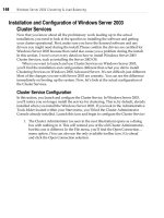
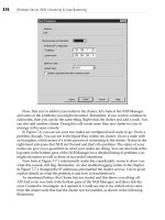
If you find your system running improperly, you might want to view the Task
Manager, as seen in Figure 2-5, and check how your virtual memory is used against
what you physically have in your machine. To open the Task Manager, right-click
your taskbar, and select it.
Pay attention to the physical memory section and make sure you’re running enough
physical memory to meet the demands of the system. If you look at the Memory Usage
bar and see that it runs higher than what you have available, then you are probably disk
thrashing (constant paging to disk) and excessively using virtual memory. (A review of
performance monitoring memory use is in Chapter 8.) If you find your system runs
poorly, you might want to look at that chapter to start resolving problems on your
production network equipment before you go live with the cluster service. To set the
page size properly, look at the amount of physical RAM you have and add 11MB to
that number. That’s it. Remember to place the paging file in the correct location (on its
own physical disk instead of the logical drive) or you can damage system performance.
Configuring Network Properties
You need to preplan your network properties seriously before you install the Cluster
Service. In this section, we configure TCP/IP communications and media speeds, so
your nodes communicate properly. We test this as well. It’s important for you to have
communication with all hosts that play a key role in your implementation on the network
before continuing with the cluster install.
If you don’t have access to IP addressing assignments, you need to contact the
department that assigns them. In larger IT shops, you’ll find that TCP/IP management
is closely monitored and you might have to get a Lead Engineer or Manager involved
to get a block of addresses you can use.
P:\010Comp\OsbNetw\622-6\ch02.vp
Monday, March 24, 2003 9:57:41 AM
Color profile: Generic CMYK printer profile
Composite Default screen
74 Windows Server 2003 Clustering & Load Balancing
OsbNetw / Windows Server 2003 Clustering & Load Balancing / Shimonski/ 222622-6 / Chapter 2
The IPs you use need to be static (not doled out from DHCP, which hands out IP
addresses via a configured scope) and they don’t necessarily need to be on the same
subnet. You can configure the cards on different networks because you’ll be dividing
the cluster into two halves. One half is the LAN connection, where your clients will
Figure 2-5. Windows Task Manager Memory and CPU details
P:\010Comp\OsbNetw\622-6\ch02.vp
Monday, March 24, 2003 9:57:41 AM
Color profile: Generic CMYK printer profile
Composite Default screen
Chapter 2: Designing a Clustered Solution with Windows 2000 Advanced Server 75
OsbNetw / Windows Server 2003 Clustering & Load Balancing / Shimonski/ 222622-6 / Chapter 2
come to access the clustered resources. The other is the Heartbeat Connection network
or the Management network, which is the node-to-node connection where the clustered
servers communicate with each other to make sure they’re operational. The best design
method to use in this scenario is to have two different subnets dividing the publicly
accessible network and the private Heartbeat network. This keeps both networks
separate. I explain all the IP address assignment and network connections in the
following sections.
Heartbeat Connection and Client Access
The first thing that needs to be done when configuring network properties is to make
sure you have two connections available to configure. Open your network and dial-up
connections by right-clicking My Network Places and selecting Properties. Or, you
can open it from the Control Panel. When you open the dialog box, you see the Make
a New Connection Wizard applet and, if your install went properly, you see two
connection icons, as listed in the next illustration. If you don’t see two connections, you
need to open the Device Manager discussed earlier and make sure you have the drivers
installed correctly for the network card. After you have properly configured the drivers,
the network connection should appear.
Windows 2000 has a great way to view your network connections. When using
Windows NT 4.0 Enterprise Edition, you had to open the general TCP/IP properties and
drop down to each NIC card listed in the properties to view its settings. Windows 2000
P:\010Comp\OsbNetw\622-6\ch02.vp
Monday, March 24, 2003 9:57:42 AM
Color profile: Generic CMYK printer profile
Composite Default screen
76 Windows Server 2003 Clustering & Load Balancing
OsbNetw / Windows Server 2003 Clustering & Load Balancing / Shimonski/ 222622-6 / Chapter 2
has improved this method by letting you give a friendly name to your connection. When
you view the network connections for the first time, you’ll see they’re named (by default)
Local Area Connection and Local Area Connection 2. To rename the connection, simply
right-click the name, and select it. In this example, you can call the connection by its
assignment, which is Heartbeat. You don’t want to name just any old interface. You
want to name the interfaces as you have them cabled in the system. The Heartbeat
network connection would be either the crossover cable you ran from one node to
the other, or the dedicated hub, switch, or VLAN you configured for the management
network.
If you already cabled the server and don’t know which is which, this is simple
to determine. With Windows 2000, you can unplug the network cable and it will pop
up in the system tray (systray) on the bottom right-hand side of your desktop. If you
unplugged the Heartbeat network cable, you’ll see the icon appear with a big red X
through it. Hover your mouse pointer over the connection icon and it will give you
a small description and details pane that either says Local Area Connection or Local
Area Connection 2. Make a note of which one it is, and then go back to your Network
Connections dialog box. Right-click the appropriate connection and rename it to Heartbeat.
Make sure you plug the cable back in. The icon should disappear, unless you configured
it to always appear, which we’ll do later in the section. Now, make sure the other network
connection is also labeled to your satisfaction. For example, this is labeled Local Area
Connection, which is its assignment. This is the connection where your network clients
will make requests of the server’s resources.
The second node can be configured exactly the same way as the first one as far as
the network connection naming and basic configurations. You’re only working on one
node at a time, so you won’t corrupt the shared storage set. Configure this one when
the time comes to bring up the second node.
IP Addressing and NIC Card Configurations
I discuss the entire TCP/IP connection settings here, but only do one node at a time.
Keeping a notepad next to you and jotting down notes on how to configure the other
node helps. Then, you can simply do it after you read this and configure the first node.
Now that you have your node network connection properties labeled correctly, you
can begin to configure your TCP/IP properties. The dialog box shown in the following
illustration has a title bar that reads Heartbeat properties. The bottom of the dialog box
shows a check box that enables the Show icon in taskbar when connected option.
P:\010Comp\OsbNetw\622-6\ch02.vp
Monday, March 24, 2003 9:57:42 AM
Color profile: Generic CMYK printer profile
Composite Default screen
Chapter 2: Designing a Clustered Solution with Windows 2000 Advanced Server 77
OsbNetw / Windows Server 2003 Clustering & Load Balancing / Shimonski/ 222622-6 / Chapter 2
Die-hard Windows veterans know this is a slight mistake in wording as the icon really
appears in the systray but, no matter, you understand the difference. You should check
this box to help you look at something quickly. Simply hover your mouse over the
connection (it will read heartbeat in the popup) and you can double-click it to get to
the properties quickly. You can also see incoming and outgoing data flow by hovering
your mouse over the icon or by double-clicking it.
I selected two identical 3COM NICs for both servers and, because they are identical,
they’re named in an ordinal fashion. Be sure to document which connection goes where
and apply labels on the server. Feel free to get a nice P-Touch—a device that enables
you to make labels—with markable tape to label everything you feel you need to see
on the server. Also, always take notes to log in as documentation later, to use for
troubleshooting. You can configure the NIC from here, as well as in the Device Manager
discussed earlier.
Your next configuration centers on the TCP/IP protocol. As mentioned in prerollout
design, you can’t use anything but TCP/IP. Not IPX/SPX or AppleTalk—only TCP/IP.
P:\010Comp\OsbNetw\622-6\ch02.vp
Monday, March 24, 2003 9:57:42 AM
Color profile: Generic CMYK printer profile
Composite Default screen
78 Windows Server 2003 Clustering & Load Balancing
OsbNetw / Windows Server 2003 Clustering & Load Balancing / Shimonski/ 222622-6 / Chapter 2
Highlight your TCP/IP protocol and select the Properties button. You will open
a dialog box, as seen in the next illustration.
You now need to configure static IP addressing for the clustered nodes. You should
have any server, printer, or network device set statically and configure all your network
clients’ PCs and laptops to grab an address from a DHCP server. You will need to
configure four interfaces with IP addresses. I list them here initially, so you can implement
for the second node that you’ll need to configure. These are the settings I configured on
my servers, so yours might be different or you can choose my settings. Just make sure
you understand the concepts explained. I also configured my Node A, so I’m in the
process of configuring Node B now. I set the TCP/IP addressing as follows:
•
Cluster-Node-B has a Heartbeat Connection IP address of 192.168.1.2,
with a 24-bit subnet mask.
•
Cluster-node-B also has a Local Area Connection IP Address of 10.0.0.3,
with a 24-bit subnet mask.
P:\010Comp\OsbNetw\622-6\ch02.vp
Monday, March 24, 2003 9:57:42 AM
Color profile: Generic CMYK printer profile
Composite Default screen
Chapter 2: Designing a Clustered Solution with Windows 2000 Advanced Server 79
OsbNetw / Windows Server 2003 Clustering & Load Balancing / Shimonski/ 222622-6 / Chapter 2
•
Cluster-node-A has a Heartbeat Connection IP address of 192.168.1.1,
with a 24-bit subnet mask.
•
Cluster-Node-A has a Local Area Connection IP Address of 10.0.0.2,
with a 24-bit subnet mask.
Both Cluster-Node-A and B have a default gateway of 10.0.0.1 /24 and I’ll be logging
into a domain controller with an IP address of 10.0.0.4, with a 24-bit subnet mask. I’ll
break these settings down for you as you configure it step-by-step. Figure 2-6 shows
you what this will look like on a topology map.
Once you get deeper into the install, you’ll see another address is needed. Don’t
worry about this now, though. Just remember I mentioned earlier that you’ll need to
Figure 2-6. High-level overview of TCP/IP configuration
P:\010Comp\OsbNetw\622-6\ch02.vp
Monday, March 24, 2003 9:57:42 AM
Color profile: Generic CMYK printer profile
Composite Default screen
allocate five IP addresses and a specific NetBIOS name for the cluster you’re configuring.
We’ve just configured the IP address for one node (192.168.1.2 /24). This is for the
Heartbeat network. Now you need to configure the node’s other network connection,
called Local Area Connection. You can select that one the same way you selected the
Heartbeat network, by right-clicking the icon in the Network Connections dialog box
and selecting Properties. When you open the dialog box, you need to configure it the
same way as you configured the Heartbeat connection, except you enter the IP address
of 10.0.0.2 with a 24-bit subnet mask. On this network connection, however, you must
configure more than just an IP address and a subnet mask. The server needs a default
gateway on the local segment to which it’s connected. Remember, this server needs to
respond to and serve resources to the network clients. You might have to configure
a default gateway (local router) if you have clients accessing your cluster from other
networks or from across a wide area network (WAN).
You eventually need an IP address for every resource you set up in your cluster.
If you set up a SQL Server 2000, you need a new IP address for it (something like
10.0.0.6 /24), but you’ll still be using the two-node cluster with IP addresses of 10.0.0.2
and 10.0.0.3. If you know you’ll be setting up quite a few clustered solutions, you might
want to ask your Network Engineer (or slot them yourself) for a block of IPs. You could
use 10.0.0.2–10.0.0.10 for the nodes and quite a few resources. If you expect more growth,
then block out some more.
Advanced Configuration and Troubleshooting for Network
Connections
Getting this right before the installation of the Cluster Services is important. Make
sure you open the Device Manager, as seen in Figure 2-7, and view the NICs for any
possible errors. Next, select each of them, one at a time, and double-click them to
access their properties.
When viewing the NIC properties, as shown in the following illustration, you can
pinpoint bus locations and see if the card is enabled. A handy troubleshooter option
can help you if you need it. You can use the troubleshooter, but the explanations of
the problems are rather vague and basic, so it might not help much.
80 Windows Server 2003 Clustering & Load Balancing
OsbNetw / Windows Server 2003 Clustering & Load Balancing / Shimonski/ 222622-6 / Chapter 2
P:\010Comp\OsbNetw\622-6\ch02.vp
Monday, March 24, 2003 9:57:42 AM
Color profile: Generic CMYK printer profile
Composite Default screen
Chapter 2: Designing a Clustered Solution with Windows 2000 Advanced Server 81
OsbNetw / Windows Server 2003 Clustering & Load Balancing / Shimonski/ 222622-6 / Chapter 2
Figure 2-7. Viewing multiple NICs in the Device Manager
P:\010Comp\OsbNetw\622-6\ch02.vp
Tuesday, March 25, 2003 11:14:15 AM
Color profile: Generic CMYK printer profile
Composite Default screen
82 Windows Server 2003 Clustering & Load Balancing
OsbNetw / Windows Server 2003 Clustering & Load Balancing / Shimonski/ 222622-6 / Chapter 2
Next, click the Advanced tab (as seen in the following illustration), so you can learn
how to configure (or hardcode) the speeds for your NIC card manually if they didn’t
autonegotiate properly or if you want to tweak a few milliseconds out of your system
by eliminating the time it takes to autonegotiate from the NIC to the Switch port. By
viewing media type, you can select to put the card at different speeds, but if you hardcode
this, make sure you know how to configure the switch on the other side of the connection,
in case it has a problem. I’ve seen cases where a skilled technician hardcoded the NIC
at 100 Mbps and couldn’t figure out why he lost the connection when plugged into a
Cisco 1900 Catalyst switch. Well, the 1900 series switch ran at 10BaseT and, because
a high-level overview and topology map wasn’t used, he assumed the speed was
100 Mbps because it was a Cisco switch.
Now, after you configure all your IPs, speeds, and connections the way you want them,
you need to run a test to make sure it all works. Because we’ve done this step-by-step—
checking along the way—it’s easy to see problems and immediately eliminate or fix
them without having to backtrack too far in the installation.
Use the command prompt for your troubleshooting. This can be pulled up quickly
by going to the Start button and opening the Run dialog box. Type CMD, and then
P:\010Comp\OsbNetw\622-6\ch02.vp
Monday, March 24, 2003 9:57:43 AM
Color profile: Generic CMYK printer profile
Composite Default screen
Chapter 2: Designing a Clustered Solution with Windows 2000 Advanced Server 83
OsbNetw / Windows Server 2003 Clustering & Load Balancing / Shimonski/ 222622-6 / Chapter 2
press ENTER. You open a Command Prompt window, as shown in Figure 2-8. Check
to see what your configuration is set at by typing IPCONFIG /ALL, and then press
ENTER. This will show you all your configuration statistics. You should jot down (or
copy-and-paste) this information for your log and documentation. You should have
Cluster-Node-A or B (or whatever you called your clustered servers). You should also
have your Local Area Connection configurations exactly as you entered them. And, you
should have your Heartbeat configurations just as you entered them in the network
properties. If you have any discrepancies, backtrack until you find your error. Next,
type PING and try to make contact with your server from a network client (or another
server). Because the Heartbeat connection is listed here, you might be unable to connect
yet—until the other server is up and running. What I generally do is set up a VLAN for
the Heartbeat and ping all NICs from within a Layer 3 switch. This is the easiest way to
verify the connectivity of your clustered node set.
Finally, you need to power down the first node you configured and power up the
second node to configure its IP addressing as well. You can do this now or wait until
you completely finish all configurations. Most of the major ones have been discussed,
but we can explore a few more topics to improve your clustered and Highly Available
solution.
Figure 2-8. Using the PING command to test connectivity
P:\010Comp\OsbNetw\622-6\ch02.vp
Monday, March 24, 2003 9:57:43 AM
Color profile: Generic CMYK printer profile
Composite Default screen
84 Windows Server 2003 Clustering & Load Balancing
OsbNetw / Windows Server 2003 Clustering & Load Balancing / Shimonski/ 222622-6 / Chapter 2
NETBIOS and WINS
NetBIOS is a protocol without legs. I won’t give a history on the NetBIOS protocol, but
it’s an integral part of pre-Windows 2000 network communications. Unless you have
100 percent Windows 2000 rolled out across your infrastructure, you’re stuck with WINS
to find and use resources on the network. Many places where I work still run Windows 95,
so NetBIOS will be a part of our IT-based lives. We need to set up NetBIOS properly on
a Windows 2000 clustered solution. In the following illustration, we revisit the network
properties for our Heartbeat connection. Open the network properties, and then go to
the advanced settings within the TCP/IP protocol stack. Click the WINS tab and you
can disable the NetBIOS resolution use for your Heartbeat connection. It’s a point-to-point
connection and it’s unneeded. You don’t want to disable this for your LAN that your
network clients access because it could create a problem with NBT resolution (NetBIOS
over TCP/IP). You can, however, add another configuration tweak into the cluster node
for better performance when you disable it on the back-end connection.
P:\010Comp\OsbNetw\622-6\ch02.vp
Monday, March 24, 2003 9:57:43 AM
Color profile: Generic CMYK printer profile
Composite Default screen
NetBIOS is broadcast-based and when you implement a Windows Internet Naming
Service (WINS) server, you can have all NetBIOS names and services log directly to a
database on a server, which cuts down broadcasting tremendously. You can configure
your network to use such a feature to control performance and bandwidth utilization
on your cluster segment.
Also, you might find your system’s Event Viewer could be filling up with
unnecessary browser announcements from your server participating in browser
wars. The network browser service manages a list of servers and services running
on your network, so all clients can find them. This is used to build a list of systems
and services found within My Network Place (formerly Network Neighborhood) for
you to access. Unfortunately, this creates unwanted traffic and fills your logs with
nonsense about elections (who will be what type of browser) and other issues about
servers being unable to participate in or losing an election. For a dedicated server set
to provide a clustered resource, you can safely assume your domain controllers can
float this list around and your cluster should ignore the possibility of using it or
participating in it.
The only way to kill the Browser Service (the service that runs on the Windows server
that allows for browser list elections) without stopping the Server Service or disabling
File and Print Sharing is to attempt a registry hack. This is safe and easy, but as always,
you should know that changes are hard to reverse and make sure you have a backup of
your registry before attempting the following hack.
You can disable the NetBIOS browser wars by making our cluster node not participate
in a browser election. Simply open your Registry Editor by clicking the Start button,
select Run from the Start menu, and type regedit in the Run dialog box. Press
ENTER
and you will open the Registry Editor, as seen in the next illustration.
Chapter 2: Designing a Clustered Solution with Windows 2000 Advanced Server 85
OsbNetw / Windows 2000 & Windows Server 2003 Clustering & Load Balancing / Shimonski/ 222622-6 / Chapter 2
P:\010Comp\OsbNetw\622-6\ch02.vp
Monday, March 24, 2003 9:57:43 AM
Color profile: Generic CMYK printer profile
Composite Default screen
Browse to the following path: HKEY_LOCAL_MACHINE\SYSTEM\
CurrentControlSet\Services\Browser\Parameters and double-click the MaintainServerList
string. You open a dialog box, as seen in the following illustration.
Change the setting from Auto to No. This will stop you from participating in the
browser wars that fill up your Event Viewer logs.
Last, you still need a reserved name for the entire cluster. A fact of networking
with NetBIOS is you can’t duplicate NetBIOS names, so this name must be unique on
the network. This is why you need to plan on the cluster name having its own unique
NetBIOS name because, if you accidentally duplicate it, you might have networking
problems when the system goes live. We use this name later when we run the install
for the cluster services. You need to name each of your cluster members, and then
name the entire cluster. You’ll see this clearly when we go through the installation
and configuration of MSCS.
User Accounts and Security
A domain user account for your Cluster Service needs to be configured on the domain
controller where your servers will authenticate. Both cluster nodes need to be part of
a domain or the service won’t install, which means they’ll have a computer account
on the domain controller.
When you join the domain, you use a service account that we’ll create later in the
chapter. I simulated a failed install to show it can’t be done until you join a domain,
which you see soon. To create an account, go to a domain controller on your network
and create a new account. You can do this by opening the Active Directory Users and
Computers MMC console. Go to your Administrative Tools folder in the Control Panel.
Create a new account by right-clicking the Users folder in the console, and then create
a new User object in the directory. You’ll open a new dialog box, as seen in the next
illustration. You can name this account anything you want, but follow the naming
convention dictated by your organization.
86 Windows Server 2003 Clustering & Load Balancing
OsbNetw / Windows Server 2003 Clustering & Load Balancing / Shimonski/ 222622-6 / Chapter 2
P:\010Comp\OsbNetw\622-6\ch02.vp
Monday, March 24, 2003 9:57:44 AM
Color profile: Generic CMYK printer profile
Composite Default screen
Chapter 2: Designing a Clustered Solution with Windows 2000 Advanced Server 87
OsbNetw / Windows Server 2003 Clustering & Load Balancing / Shimonski/ 222622-6 / Chapter 2
If your organization doesn’t implement a naming convention (this is a bad thing),
then make up an account that you’ll know by looking at the name, for example,
Cluster_Service. When you finish, click Next, and then select a password that can’t
be guessed or easily hacked. I generally select a password from a phrase (which is
one of the best ways to create a secure password). You can use something like, “My
dog loves to play catch with a black Frisbee,” and use the first letter from each word,
which creates the password, MDLTPCWABF. Now that you’ve selected a good password,
select the two check boxes, as seen in the following illustration, for Password never
expires and User cannot change password. Uncheck the option to have the user change
the password at the next logon.
P:\010Comp\OsbNetw\622-6\ch02.vp
Monday, March 24, 2003 9:57:44 AM
Color profile: Generic CMYK printer profile
Composite Default screen
88 Windows Server 2003 Clustering & Load Balancing
OsbNetw / Windows Server 2003 Clustering & Load Balancing / Shimonski/ 222622-6 / Chapter 2
Click Next and finish the User objects’ basic settings. Once you finish and the new
Cluster_Service object is created, you need to configure it further with one quick tweak
I mentioned before. You don’t want to run login scripts that could conflict with drive
mappings used on the cluster for shared storage because this might cause a problem.
Be aware of this or create a separate script and assign it explicitly to the user, so it
won’t alter the drive mappings on the clustered nodes. If you have a problem with
this, either take the script out or designate the specific user with a customized login
script, as seen in the next illustration.
Cluster Service Account Advanced Configuration
In this section, I discuss other ways to configure the account, Cluster_Service. The
reason it’s so important that you know how to configure this account is this: if you ever
change anything with this account, if someone else accidentally changes something, if
you assign a different account, or any reason whatsoever, you’ll need to know how to
reconfigure the account in which we named Cluster_Service from before. Note these
important points about the Cluster Service account:
•
The account must be a domain account (created on a domain controller)
•
The account must have local administrative rights to every node in your cluster
If you need to add the account to local machines, all you need to do is open the
Computer Management Console for each node and go to the Local Users and Groups
P:\010Comp\OsbNetw\622-6\ch02.vp
Monday, March 24, 2003 9:57:44 AM
Color profile: Generic CMYK printer profile
Composite Default screen