Practical Arduino Cool Projects for Open Source Hardware- P35 pptx
Bạn đang xem bản rút gọn của tài liệu. Xem và tải ngay bản đầy đủ của tài liệu tại đây (212.11 KB, 10 trang )
CHAPTER 15 VEHICLE TELEMETRY PLATFORM
c2 Direction of longitude: E = East, W = West (a).
d1 Position type: 0 = Invalid or not available, 1 = Autonomous
position, 2 = RTCM or SBAS differentially corrected (n).
d2 Number of satellites used in position computation (nn).
f1 Horizontal dilution position: HDOP (nn.nnn).
f2 Altitude in meters above the reference ellipsoid. For 2-D position
computation, this item contains the user-entered altitude used to
compute the position computation.
M Altitude units: M = meters (a).
f3 Geoidal separation in meters (+/–ddd.dd).
M Geoidal separation units: M = meters (a).
d3 Age of differential corrections in seconds (nnn).
d4: Base station ID for RTCM use only (nnnn).
cc Checksum.
Most developers think of NMEA 0183 only as a way to talk to GPS receivers, but it’s actually a much
more general communications protocol that is used in marine environments for a whole range of
devices including echo sounders, autopilots, and weather sensors. Wikipedia has more information
about the NMEA 0183 standard at en.wikipedia.org/wiki/NMEA_0183.
Assemble the Power Supply on the Shield
Normally, the power supply circuit is the most boring part of a project, but this one has a few tricks that
are worth paying close attention to. See the schematic in Figure 15-17.
319
CHAPTER 15 VEHICLE TELEMETRY PLATFORM
Figure 15-17. Schematic of Vehicle Telemetry Platform power supply
Because this system will run directly from the car’s power, we need to regulate it down from the 12–
14V range provided through the OBD-II connection to a nice, consistent 5V.
However, keep in mind for other automotive projects that although the vast majority of cars operate
on a 12V negative-ground system, there are exceptions: many trucks operate at 24V, motorcycles at 6V,
and some modern cars use an internal 42V power bus.
Because we’re using the OBD-II connector as the power source, and the OBD-II standard stipulates
that it supply 12V, we’re fairly safe. But if you try connecting directly to a vehicle power supply, there
may be cases where you see something other than 12V. To regulate the 12V supply down to 5V, we’re
using an LM2940CT-5 linear voltage regulator, which is the automotive-rated version of the ever popular
LM7805 voltage regulator. If you’ve used an LM7805 in another project, then an LM2940CT-5 will seem
perfectly familiar: it’s in the same physical package, it has the same pinout, and you can drop it directly
into a circuit where you would normally use an LM7805 and it will simply work. Reference schematics
for the LM7805 abound online, so it’s easy to figure out how to hook them up.
You might be wondering why we didn’t simply use an LM7805 and went instead for a much more
expensive and sometimes hard-to-find, but otherwise apparently equivalent, part.
The answer is found in the electrical environment of a typical car, which runs most commonly at a
nominal 12 to 14 volts but can vary wildly outside that range. While powering the starter motor, the
battery has to supply an enormous current for several seconds, during which time the voltage across the
battery terminals can often drop to as little as 6V. The LM2940CT-5 is designed to allow for that and is an
“LDO” or “low drop-out” regulator that can maintain its output voltage at a stable level when the input
falls to just 0.5V above the required output. A traditional LM7805, by comparison, needs its input to be at
least 2V higher than the desired output. This means an LM7805 can’t maintain a 5V output unless you
feed it at least 7V on the input. Dropping the input to 6V on an LM7805 could cause your Arduino to
spontaneously reset, but an LM2940CT-5 will handle it with ease.
Other than handling under-voltage situations better, the LM2940CT-5 also handles over-voltage
spikes and even reverse-voltage inputs far better than an LM7805. Car electrical systems can sometimes
experience a phenomenon known as “load dump,” when the alternator pushes voltage spikes of 60V or
more onto the wiring loom momentarily. This can happen when a battery connection is a little bit loose
and the load being driven by the alternator suddenly decreases, causing it to dump the excess power
onto the wiring loom in the form of increased voltage before the alternator’s built in output monitoring
circuit has time to react. Jump-starting a car can have similar nasty effects as the batteries and
alternators of both cars interact with each other as the second car starts up and also as the jumper leads
are unplugged.
320
CHAPTER 15 VEHICLE TELEMETRY PLATFORM
The result of all this is that you can use an LM7805 voltage regulator in an automotive project if you
really want to, and it will probably work fine for a while, but it’s quite likely that it will eventually find the
noisy electrical environment of a car too much to handle and stop working. It’s better to save yourself
the grief and use a proper automotive-rated voltage regulator right from the start. Automotive-rated
parts were designed for a reason, after all!
If you were sharp-eyed, you probably noticed that the ELM327 adapter shown back in Figure 15-7
has a regular LM7805 in it because it’s not intended to be left connected permanently and the
manufacturer wanted to save a couple of dollars in their manufacturing costs. If you were feeling
paranoid, you could clip the LM7805 out and replace it with an LM2904CT-5, but that’s probably not
worth the effort unless it happens to fail.
The other thing that is a little bit unusual about our power supply circuit is that we’ve deviated from
the typical reference design by fitting an enormous capacitor across the voltage regulator input and
feeding the input through a power diode. We’ve also included a voltage divider in front of the power
diode and a Zener diode to act as a voltage clamp on the bottom of the divider.
The reason for doing this is to give the Arduino the ability to elegantly handle power failure. Having
a very large capacitor on the input of the voltage regulator provides enough reserve power to keep the
voltage regulator running at its rated voltage for a few extra milliseconds after power is disconnected
from the input. By having the CPU detect input failure through the voltage divider, it can use that time to
quickly put its house in order before the power drops out entirely. Tasks it might need to do in that time
include closing any files that are open on the USB memory stick, because if the power fails while a file is
open it probably won’t be written properly and could end up corrupted or even entirely empty with all
your logged data gone forever.
Fit the LM2940CT-5 to the prototyping shield, with the common (center) pin connected to ground
on the shield and the output (right) pin connected to +5V. The Mega prototyping shield from NKC
Electronics we used in our prototypes has handy ground and 5V rails beside each other down the center
of the board, so the voltage regulator can be fitted straight across them with two of the pins on the two
supply rails. The input (left) pin will eventually be connected to the car’s +12V supply line via the OBD
adapter.
If the pins of the voltage regulator are just a little too big to fit comfortably through the holes in the
prototyping shield, you can cut them off to about half length and very carefully trim a fraction off the
thickness of each leg with wire cutters or a small file. You could alternatively drill out the holes in the
PCB with a slightly larger drill bit, but if you do that you’ll also remove the through-hole plating inside
the holes, so make sure you solder the pins into place on both the top and bottom of the PCB. You also
need to be careful not to short out the ground plane if there is one on the particular shield you use.
Also connect the 47uF electrolytic capacitor between the output pin and ground. This capacitor
provides high-frequency damping of the output of the regulator and helps the voltage regulator
maintain a constant voltage. The specifications for the LM2940CT-5 state that it needs a capacitor of at
least 22uF connected to the output stage for stable operation, but we increased this value to 47uF to
provide a bit of extra decoupling.
You’ll note that the parts list specifies that the 47uF capacitor should be rated to no more than 16V,
which at first sounds like a very odd requirement. Normally it’s fine to use parts that are rated for a
higher voltage than required, but in this case it can actually cause problems. In a perfect world,
capacitors would only ever exhibit capacitance and have zero resistance or inductance, but the reality of
the manufacturing techniques and materials used in the physical construction of capacitors means they
tend to exhibit a small amount of resistance as well. This is referred to as ESR, or equivalent series
resistance, and tends to be higher for capacitors rated to higher voltages. The ESR limits the ability of a
capacitor to charge or discharge rapidly, preventing it from following high-frequency voltage transients.
To minimize ESR, it’s a good idea to use a 10V- or at most a 16V-rated electrolytic in this case, and
ideally one specifically rated as “Low ESR” if available. If all else fails, another solution is to put a second,
smaller value capacitor (perhaps 100nF or so) in parallel.
321
CHAPTER 15 VEHICLE TELEMETRY PLATFORM
The smaller capacitor will help follow high-frequency transients while the larger one will store a
larger amount of energy, and between them they will keep the regulator stable. When connecting the
47uF electrolytic, make careful note of the polarity—electrolytics have a nasty habit of going BANG and
making a smelly, smoky mess if they are connected backward! Electrolytic capacitors usually have the
negative lead marked on the case, and also have their leads cut to different lengths with the positive lead
longer than the negative lead. The negative lead goes to ground, while the positive lead goes to the
output of the regulator.
Also install the 4700uF electrolytic capacitor between the input pin and ground, once again noting
the polarity. The negative (short) lead goes to ground, while the positive (long) lead goes to the input of
the regulator. For this capacitor, we specified a 63V or greater rating because it could potentially be
exposed to 60V spikes if the alternator ever load-dumps into the loom. The only part we could find
locally was a 50V-rated version, but if you can find a 63V or higher rating, that’s preferable. A large value
capacitor in a high-voltage rating is likely to be physically very large, and you can see that the one we
used is about the size of a C-cell battery. There was no way to mount it neatly on the shield, so we had to
fit it elsewhere in the case and use short lengths of hookup wire to connect it to the circuit.
Next, fit a 1N4001 or equivalent power diode so that the cathode (banded) end connects to the input
pin of the LM2940CT-5, which is also where the positive lead of the 4700uF capacitor is connected. The
+12V supply from the car will need to connect to the anode (nonbanded) end, so you can either solder a
piece of wire directly in place for the +12V connection or do what we did and fit an oriented 2-pin
captive terminal with the other terminal pin connected to ground on the shield. This way, you can make
up a handy cable to link to +12V and ground connections from the OBD-II adapter, which has direct
access to vehicle ground and power through the OBD-II connector.
In order to detect power loss, the Arduino needs an input from the unregulated (+12V) side of the
power-supply circuit. The input needs to change state fast enough for it to be detected and necessary
action taken before the large capacitor on the input has time to discharge below the voltage regulator’s
minimum stable input voltage of about 5.5V. Because the electrical system of a car can be very “noisy”
with spikes and transient voltages, it’s a good idea to keep the Arduino on the regulated side of the
circuit as decoupled from the input side of the power supply as possible. To achieve power-supply
sensing, we used a pair of resistors as a voltage divider and a Zener diode as a voltage clamp with the
output connected to a digital input on the Arduino.
The voltage divider connects directly in front of the power diode so that it samples the voltage being
supplied to it. If the input voltage falls, the voltage divider will see the drop immediately, even though
the large capacitor on the voltage regulator input will remain high for a while. The diode prevents the
capacitor from discharging back through the voltage divider and vehicle wiring loom and fooling the
Arduino into thinking the input voltage is still normal until it’s too late.
The voltage divider consists of a 100K upper half and a 47K lower half. The result is that the output
of the voltage divider will be the input voltage times a factor of
47 / (100 + 47) = 0.32
So with a 12V input to the top of the divider, the output will be
12 × 0.32 = 3.84V
With a 14V input, the output will be
14 × 0.32 = 4.48V
We can also work back the other way to figure out the threshold at which the input voltage causes
the output to fall low enough for the Arduino to detect a “logic low” level and begin its emergency
shutdown procedure. The upper threshold for an input low voltage on ATMega CPUs is 0.3 × supply
voltage. So for a CPU running at 5V, the trigger point for an input to see a logic low is any voltage below
1.5V.
The minimum voltage that needs to be applied to the top of the voltage divider to cause the input to
see 1.5V or more can be calculated as follows:
1.5 / 0.32 = 4.7V
322
CHAPTER 15 VEHICLE TELEMETRY PLATFORM
Simply dividing the voltage down isn’t quite enough protection for the Arduino input, though.
Imagine what would happen in the case of a load-dump when the alternator pumps 60V into the
system—the voltage divider output would rise to 19.2V!
The 5.6V Zener diode across the 47K resistor provides that extra protection. A Zener diode has the
unusual property that when exposed to a reverse-biased voltage below a specific “Zener voltage” it acts
as an open circuit and you would hardly know it’s there, but if the voltage rises above that point the
Zener diode begins to conduct almost like a short-circuit. The result is that it can act as an over-voltage
protection clamp that prevents the Arduino input from seeing a voltage beyond its rated level.
Combined with the high-impedance input presented by the voltage divider, it provides pretty much
bulletproof protection against anything a car electrical system can throw at it.
Note that although Zener diodes have a specific rated voltage, their conductivity isn’t quite as binary
as being totally off below that voltage and totally on above it. They begin to conduct gradually a little
below the rated voltage, which is why we chose a 5.6V Zener to protect a 5V input. If we’d chosen
something like a 5.1V Zener instead, it would actually start clamping the input prematurely once it rose
above about 4.7V or 4.8V. The 5.6V part we selected is just right for protecting a 5V input.
Fit the pair of resistors for the voltage divider, with one end of the 100K resistor joined to the +12V
input, the other end joined to the 47K resistor, and the far end of the 47K resistor joined to ground as
shown in the power supply schematic in Figure 15-17. Connect the Zener diode in parallel to the 47K
resistor with the banded (cathode) end to the joint between the resistors, and the nonbanded (anode)
end connected to ground. Then fit a jumper wire that connects the center of the voltage divider to the
Mega’s digital I/O pin 2. This input is used specifically because it can have an interrupt attached to it in
the ATMega1280 CPU, allowing the software to detect changes to it at any time without having to
continuously poll the input to see if it has changed. In the software, we will attach a “falling edge”
interrupt to pin 2 so that if the voltage transitions from a high state to a low state the program will enter
an emergency shutdown mode to protect the data on the USB memory stick.
As a general principle, it’s a good idea to always test a newly constructed power supply in isolation
from the rest of the circuit. With the shield separate from the Arduino and nothing else fitted on it,
connect a +12V power supply to the ground and voltage regulator input connections, and use a
multimeter to measure the voltage between the ground and +5V rails on the shield. It should be in the
range 4.95V to 5.05V if everything is connected properly. Also measure the voltage on the center of the
voltage divider where it connects to Arduino digital I/O pin 2, and make sure it’s at the level you expect
based on your actual power-supply input voltage and the calculations shown previously.
Fit the Serial Connections on the Shield
Because both the GPS module and the OBD-II adapter use serial interfaces, we need to fit two oriented
4-pin male headers to the prototyping shield for the serial connections. To keep the wiring simple, we
fitted them at the end of the board near the Arduino’s serial I/O pins.
RX and TX (the first serial port on the Arduino) aren’t used by any peripherals, so they remain free
for a host to connect to the data logger.
Link the OBD-II serial connection ground pin to ground on the shield, and run short jumper wires
to link the RX pin to the Mega’s RX1, and the TX pin to the Mega’s TX1. These two connections are for
the second serial port on the Mega, named “Serial1” because port numbering starts from 0. Technically,
the first serial port is Serial0 even though the name is abbreviated to simply “Serial.” You don’t need to
connect the VCC pin on the serial connector to anything because, as mentioned previously, we don’t use
it to power the OBD-II module. Only ground, TX, and RX need to be connected.
Likewise, link the GPS serial connection ground pin to ground on the shield and run short jumper
wires to link the RX pin to the Mega’s RX2, and the TX pin to the Mega’s TX2. These serial connections
are for the third serial port on the Mega, named “Serial2.” Yes, the naming can be a bit confusing
sometimes!
323
CHAPTER 15 VEHICLE TELEMETRY PLATFORM
Because the GPS module needs to be powered from the Arduino, we do need to connect up the VCC
pin, but because we’re using an LS20031 that runs at 3.3V we can’t simply link the serial VCC line to +5V
on the shield. Instead it needs to be connected to the 3.3V header on the shield using a short piece of
hookup wire.
The two serial ports are wired up in almost exactly the same way, and as far as software is concerned
they are interchangeable, but because of the different connections for power it’s important to keep track
of which one is which. Make a note or put a mark on the board to show which is the OBD-II socket
(Serial1, no power) and which is GPS (Serial2, 3.3V).
Prepare the VDIP1 Module
A recurring question on Arduino mailing lists, forums, and blogs is how to connect it to some form of
mass-storage device to keep a record of data collected from sensors and inputs. The Arduino’s ATMega
CPU contains nonvolatile storage called EEPROM (Electrically Erasable Programmable Read-Only
Memory), but it has very small capacity: 512bytes in the ATMega168, 1KB in the 328P, and 4KB in the
1280. We use it in this project to store configuration values entered via menus on the LCD, but for storing
a larger amount of data we have to look elsewhere. More information about the internal EEPROM is
available on the Arduino site at www.arduino.cc/en/Reference/EEPROM.
The next step up in capacity is direct connection to flash memory chips that are fairly commonly
available in the region of 1Mbit (128KB) to 4Mbit (512KB) capacity. With an external flash memory chip,
the Arduino can certainly store more data, but it’s still trapped within your project and can’t be easily
accessed externally. If you want to access the data later, you will need to have a routine in the Arduino
that can read it back out and send it to a host via the serial port or a network connection, and then have a
program at the other end capable of reading and storing the stream of data. It’s also just a big flat chunk
of memory, so you have to keep track of what data you have stored and where it’s located within the
memory space, because it has no concept of a filesystem. Flash memory chips are typically connected
using SPI (Serial Peripheral Interface) or I2C, both of which are very well supported by Arduino. See
www.arduino.cc/playground/Code/Dataflash or www.arduino.cc/playground/Code/I2CEEPROM for
more information.
Beyond directly connected flash memory chips is the use of things such as MicroSD flash memory
cards, commonly used in digital cameras. They’re inexpensive, small, and have large capacities: not just
megabytes of data, but gigabytes. Something not many people realize is that MicroSD memory cards
support a standard SPI connection just like flash memory chips, so they’re quite easy to communicate
with. One approach that a number of people have taken is to solder wires directly to the metal tabs on a
MicroSD card and talk to it directly from an Arduino. Once again, the filesystem itself is the stumbling
block, though, because attempting to implement support for even a limited subset of something like a
VFAT filesystem on a microcontroller such as an Arduino would use up all its resources and render it
pretty much useless for anything else. If you want to go down that path, it’s worth looking at a library
called SDuFAT (SD micro FAT) that implements a very minimal subset of the FAT filesystem. It works by
relying on a host computer to prepare the filesystem and create a single large empty file in advance,
which it then fills with whatever data you want to write into it. See
www.arduino.cc/playground/Learning/SDMMC for more information.
For this project, though, we’ve gone another step further again, using a standard USB memory stick
formatted with a full FAT16 or FAT32 filesystem. This is the Holy Grail of Arduino mass storage: large,
cheap, fast, removable, and the data written to the memory stick is then accessible using standard
software such as a text editor or a spreadsheet on a regular PC. We can create files and directories, delete
them, and read and write them all using simple routines in an Arduino program. Perfect for a data-
logging application like this.
All this is made possible by a chip called a Vinculum VNC1L made by FTDI, the same folks who
created the USB interface adapter used in many Arduino models including the Duemilanove and the
324
CHAPTER 15 VEHICLE TELEMETRY PLATFORM
Mega. The VNC1L builds on their experience creating USB-to-serial interface chips and implements an
entire dual-channel USB host/slave device in a single chip.
This sounds great in theory, but the VNC1L comes in an LQFP-48 format—fine if you have your own
reflow soldering oven and SMT production line at home, but not so useful if you want to solder it by
hand. Luckily, FTDI also supplies the VNC1L preloaded on a handy prototyping module that’s available
in both single-port (VDIP1) and dual-port (VDIP2) formats at a very reasonable price. The VDIP1 (see
Figure 15-18) is perfect for this application and is available for purchase online directly from FTDI’s
online store at www.vinculum.com, and also from regional distributors such as Dontronics in Australia.
It’s a really neat solution that should become very popular as a way to add mass storage to Arduino
projects.
Figure 15-18. The VinculumVDP1 single-port USB module
Both the VDIP1 and VDIP2 modules contain the same VNC1L chip, and in fact the only difference
between them is that one has a single USB socket fitted to it and the other has a pair of sockets. Other
than that, they are identical and can run the same firmware, and in fact all the connections for the
second USB port are included on the single-port VDIP1 so you can even wire up a second connector to it
yourself.
The VNC1L can be loaded with a variety of different firmware variations so that the two channels
can be any combination of USB client and USB host. The first step is to select the firmware that’s most
appropriate to our particular application and flash the chip.
One of the neat features of the VNC1L is that it can perform its own firmware updates directly from a
memory stick. Just download the required firmware from www.vinculum.com, put it onto a memory
stick, and rename it “ftrfb.ftd.” Then plug the memory stick into the VDIP1 module and power it up. The
VNC1L chip searches memory sticks connected to it for a replacement firmware file that is a different
version than the one already installed, and if it finds one it loads the new firmware into its internal
nonvolatile memory and then automatically reboots. The whole process is totally painless and changing
firmware versions couldn’t be easier.
For this project, we use what FTDI refers to as “VDAP” (Vinculum Disk And Peripheral) firmware,
which allows it to act as a USB host to other USB slave devices, such as memory sticks and other
peripherals, and includes FAT support. If your VDIP1 module was supplied with a different firmware
325
CHAPTER 15 VEHICLE TELEMETRY PLATFORM
preinstalled, you’ll need to download the VDAP firmware from www.vinculum.com and install it using
the process just discussed.
The VNC1L supports three communication modes: serial UART, SPI, and parallel FIFO. For this
project, we used a serial connection with the VDIP1 in UART mode. The communication mode is set
using the jumpers on the pair of 3-pin headers at one end of the board, and putting both jumpers into
either pull-down (left) or pull-up (right) positions will select UART mode. The supported jumper modes
are shown in Figure 15-9.
Figure 15-19. Mode jumpers for VDIP1 and VDIP2 modules
The data pins on the VDIP1 have different meanings depending on the communications mode. The
VDIP1 datasheet includes pinout tables for all modes including SPI and parallel FIFO, but we’re using
serial UART mode so we’ll use the UART pin assignment shown in Table 15-5.
Table 15-5. VDIP1 pinout in UART mode
Pin Name Type Description
6 TXD Output Tx data output
8 RXD Input Rx data input
9 RTS# Output Request To Send (active low)
10 CTS# Input Clear To Send (active low)
11 DTR# Output Data Terminal Ready output (active low)
12 DSR# Input Data Set Ready input (active low)
13 DCD# Input Data Carrier Detect input (active low)
326
CHAPTER 15 VEHICLE TELEMETRY PLATFORM
14 RI# Input Ring Indicator input (active low)
15 TXDEN# Input Enable Tx for RS485 (active low)
We use only TXD, RXD, RTS, and CTS connections for OBDuinoMega, so pins 11 through 15 can be
ignored.
Other than the specific communications pins, the other ones we need to be concerned with are VCC
(+5V), GND, PG (program), and RS (reset). VCC and GND connect directly to +5V and GND on the
Arduino via the prototyping shield, while both PG and RS are active-low so they need to be biased high
to +5V via 10K resistors to disable them.
Being able to apply a hardware reset to the VDIP1 under software control can be very handy during
development, so also connect the RS pin to Arduino digital I/O pin 12 via a 1K resistor. By setting pin 12
HIGH in normal operation, it’s then possible to force the VDIP1 to reset by pulsing it LOW.The
schematic in Figure 15-20 shows the connections required from the Arduino to the VDIP1 module.
Figure 15-20. Schematic for connections to VDIP1 module
The VDIP1 module could be mounted directly on the prototyping shield, but for ease of access we
decided to mount ours on a subassembly glued in place near the front of the case. We first fitted a pair of
12-pin female headers to the prototyping shield to suit the VDIP1 pinout and mounted the associated
pull-up and communications resistors on the shield so that the module could be plugged straight in for
early testing. Later we used a pair of 12-pin breakaway male headers and some ribbon cable to make
mini “extension leads” that connect the subassembly in the front of the case to the headers on the
prototyping shield
327
CHAPTER 15 VEHICLE TELEMETRY PLATFORM
The LCD Module
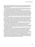
Most OBDuino and MPGuino units are fitted with a 16x2 LCD module with a Hitachi HD44780-
compatible parallel interface similar to the unit used in the Water Flow Gauge project in Chapter 10. The
code has been written to support displays of varying widths and either two or four rows, so by changing
a few configuration values you should be able to connect any HD44780-compatible module. We used the
schematic shown in Figure 15-21 with both 16x2 and 20x4 versions when building our prototypes.
Figure 15-21. Schematic for connecting the HD44780-compatible display module to Arduino
If you are intending to mount the device in your car so that you can see the LCD while driving, it’s
important to select a display that has a high level of contrast and readability. Some displays, including
one of the white-on-blue 20x4 units we used, might look cool but have pathetically poor contrast and are
very hard to read unless you’re at exactly the right angle. The early black-on-yellow/green LCD design
might look a bit dated, but it generally gives the best contrast out of all the color combinations.
An alternative is to go for a more exotic display type. Vacuum-Flourescent Display (VFD) and
Organic LED (OLED) modules with HD44780-compatible interfaces are available from some suppliers.
They are much harder to find and generally more expensive than regular LCD modules, but they give a
far brighter and more legible display, so it may be worth tracking one down if display clarity is critical to
you.
The Water Flow Gauge in Chapter 10 has a description of how HD44780 displays work and includes
an example of driving a display in 4-bit mode using the LiquidCrystal library. This project deviates from
the normal approach, though, because MPGuino/OBDuino don’t use the LiquidCrystal library. Instead
they implement their own LCD driver functions that are optimized to be as small as possible and only
328