Practical Arduino Cool Projects for Open Source Hardware- P13 ppt
Bạn đang xem bản rút gọn của tài liệu. Xem và tải ngay bản đầy đủ của tài liệu tại đây (281.59 KB, 10 trang )
CHAPTER 6 SECURITY/AUTOMATION SENSORS
Home Security System
We have presented this system as simply a way to read security sensors, but it could be extended to build
a complete home alarm system controlled by an Arduino. Alarm systems consist of several subsystems
including the alarm panel, which is the cental control system that runs the show. The alarm panel needs
to be securely locked away inside the house and innaccessible. It is often fitted inside a metal case that is
mounted inside a cupboard or inside the ceiling. To build your own alarm panel, you could mount the
Arduino inside a box and hide it.
An alarm system also needs a mechanism for arming and disarming it. This is often done using a
numeric keypad mounted in an easily accessible location, and containing no critical functionality that
could disable the alarm panel. Intruders should be able to smash or tamper with the keypad without
preventing the alarm panel from being activated. Another mechanism to arm or disarm the system could
be the RFID reader project in Chapter 14. Rather than trigger a strike plate, you could have the RFID
reader deactivate the security system.
Of course, an alarm system also needs a way to get attention, so you could wire up a relay using the
transistor circuit used in the RFID Access Control System project so that it activates a siren and a
flashing light. You could even use your Arduino to control a phone dialler or send an SMS.Battery
backup is also an important part of a security system. By combining a sealed lead acid battery, a
plugpack, and a battery charger, you can ensure your security system will run for many hours or days
even if the power to your house is cut.
Multiple Buttons on One Input
Using an analog input to read the value on a multistate voltage divider is a very handy trick that can also
let you connect multiple buttons to a single analog input. If you’re running low on digital I/O lines and
want to connect more buttons to an Arduino, you can set them up as a resistor ladder that will allow any
one of them to close a circuit and apply a different resistance to one side of a voltage divider. In the
example shown in Figure 6-18, the pull-down resistor to ground could be 100K and all the resistors in the
ladder 10K. With no buttons pushed the analog input will be pulled down hard to 0V.
However, if the first button is pushed, a voltage divider will be created with 10K pulling the pin up
and 100K pulling it down, so the voltage applied to the input will be (100 / (10 + 100) × 5V, or about
4.55V.
If the second button is pushed, a voltage divider will be created with 20K pulling the pin up and
100K pulling it down, so the voltage applied to the input will be (100 / (20 + 100) × 5, or about 4.17V.
The third button sets up a voltage of about 3.84V, the fourth about 3.57V, and so on.
You might notice that for each subsequent button the voltage difference between it and the
previous switch decreases, making it increasingly difficult to distinguish between them on the analog
input. To increase the voltage separation as you move further down the chain, it’s necessary to
progressively decrease the resistance, so in practise you might find it works well to use, say, 33K for the
first two resistors, then 18K, then 10K, then 4K7. With a bit of judicious calculation you can string quite a
number of buttons onto a single analog input pin and distinguish between them by checking the value
returned by analogRead().
If you look at the resistor ladder schematic in Figure 6-18 you may wonder why the first 10K resistor
has been included at all. After all, if that resistor wasn't included you could simply detect the first button
being pressed by measuring a voltage of +5V being applied to the input for an analog reading of 1023 or
very close to it.
99
CHAPTER 6 SECURITY/AUTOMATION SENSORS
100
Figure 6-18. Resistor ladder connected to analog input
The reason for including that resistor is to allow detection of simultaneous presses of multiple
buttons. Without the first resistor, pressing the first button will pull the analog input hard to +5V no
matter what any of the other buttons do. With the resistor in place, however, combinations of buttons
will produce different voltages and it's possible to detect which combination is being pressed at any one
moment. One common real-world application of this technique is the buttons often found on car
steering wheels to control the sound system, cruise control, and other vehicle functions. Because a
steering wheel has to be able to turn, it’s quite tricky getting connections from the static wiring loom
under the dash to buttons mounted on the wheel itself, and car designers often use tricks like spring-
loaded pads mounted on the steering assembly that slide around conductive rings that go around the
steering column. The more connections that have to be made to the steering wheel, the harder it is to
engineer the coupling, so most steering wheel controls use resistor ladders to allow up to a dozen
buttons to be placed on the steering wheel, while using only one or two connections in addition to the
ground connection back through the metal structure of the steering shaft.
If you want to modify your car by adding something such as a PC-based onboard entertainment
system to replace the existing sound system, it’s therefore possible to use an Arduino connected to the
original steering column wiring to read the button presses on the steering wheel and pass button press
events on to another device.
C H A P T E R 7
Online Thermometer
Arduino makes a great building block for data acquisition and logging systems, including sensors
commonly used in home automation such as temperature sensors. By combining an Arduino and a few
DS18B20 temperature sensors, you can install sensors around your home or office and access an up-to-
the-moment report using a web browser.
Readings can also be logged and graphed over time, showing trends or measuring the effectiveness
of your home heating or cooling systems. By placing sensors outside the house, inside your ceiling
cavity, and inside every room, you can plot how well your home maintains its temperature when climate
conditions change.
The information can also be used as part of the feedback loop for a control system, such as to
control active heating or cooling, or to trigger servos or linear actuators to open and close windows and
passive ventilation systems. The required parts are shown in Figure 7-1, and the complete schematic is
in Figure 7-2.
Parts Required
1 Arduino Duemilanove, Arduino Pro, Seeeduino, or equivalent
1 Seeed Studio Ethernet Shield or nuElectronics Ethernet Shield with prototyping
shield
6 DS18B20 Dallas 1-wire temperature sensors (Note: not DS18S20)
6 4K7 1/4W resistors
6 PCB-mount 3-pin male connectors
6 Lead-mount 3-pin female connectors
Twisted-pair cable or alarm cable (minimum 3 conductors)
Source code available from www.practicalarduino.com/projects/online-
thermometer.
101
CHAPTER 7 ONLINE THERMOMETER
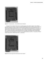
Figure 7-1. Parts required for online temperature sensor
Figure 7-2. Circuit diagram of one channel
102
CHAPTER 7 ONLINE THERMOMETER
Instructions
There are a variety of Ethernet adapters for Arduino, but for this project we chose a Seeed Studio
Ethernet Shield because the designers at Seeed Studio were clever enough to realize something very
important: most people who add Ethernet to an Arduino also want to add other custom parts as well. It’s
not very often that you’d plug an Ethernet shield into an Arduino, connect up power and network, and
let it run just like that. Most of the time you want to add other devices to the spare Arduino inputs or
outputs so it can do something useful, but every other Ethernet shield we’ve seen wastes a large part of
the shield area with blank PCB—not very useful. What Seeed Studio did is cram all the Ethernet circuitry
up toward one end of the board and then use the remaining space to provide a prototyping area with all
the Arduino I/O pins helpfully brought out on pads at the edge. Hallelujah!
But it’s not all cookies and cream. The Seeed Studio Ethernet Shield is based on the design of the
NuElectronics Ethernet Shield and requires use of the NuElectronics etherShield library. Unlike the
official Arduino Ethernet library, which hides the gory details of TCP/IP and lets you create a simple
network client or server with only a few lines of code, the etherShield library exposes a lot of the
nastiness you shouldn’t have to care about, and it can make your Arduino program quite hard to
understand. The version of the etherShield library commonly available for download (v1.0) also has a
bug that prevents it from operating correctly on computers with a case-sensitive filesystem, such as
most Linux machines, so an updated release (v1.1) is available for download from the Practical Arduino
web site.
The result is that the example code in this project will only work as-is with the Seeed Studio and
NuElectronics shields, and not with Ethernet shields based on the “official” design. However, a version
of the code modified to operate on an official shield is also available for download from the Practical
Arduino web site. If you use a shield other than the Seeed Studio design, though, you will probably have
to assemble the project using a prototyping shield that plugs on top of the Ethernet shield rather than
have everything on one board.
Mount PCB Plugs on Shield
To make the shield easy to test, it’s a good idea to use plugs and sockets to connect external devices,
such as the DS18B20 temperature sensors. That way, you can easily plug and unplug things while you’re
working with it on your bench and also while you’re installing it in a more permanent location.
We used 3-pin PCB-mount headers on our prototype because they’re inexpensive, don’t take up
much space on the shield, and only allow you to fit the connectors one way around so it’s almost
impossible to plug in a sensor backward.
The Seeed Studio Ethernet Shield has plenty of space to easily fit six connectors. In fact, if you fitted
another three across the top prototyping area and a third connector just to the left of the one marked
“E,” you could fit up to 10 on the shield. That won’t leave you with enough digital I/O lines on the two
digital connectors at the top of the shield (considering that the Ethernet shield itself uses pins 3, 10, 11,
and 12 to communicate with the Arduino). However, something that many people don’t realize is that
the analog inputs on the bottom of the Arduino can also be used as digital I/O pins.
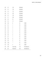
The Arduino’s analog pins can also be addressed as digital pins 14 through 19, as follows:
analog 0 = digital 14
analog 1 = digital 15
analog 2 = digital 16
analog 3 = digital 17
analog 4 = digital 18
analog 5 = digital 19
103
CHAPTER 7 ONLINE THERMOMETER
For example, to use analog pin 3 as a digital input you could simply do the following:
pinMode(17, INPUT);
This is something very handy to keep in mind if you run out of digital pins and don’t need all the
analog inputs.
The example sketch provided for this project only addresses six temperature sensors, but it could
easily be extended to read 10 if you really wanted to pack as much on the board as possible.
Connect +5V and GNDAfter you have soldered the connectors in place on the shield, strip off a short
length of single-core cable (conductors out of Ethernet cable offcuts work great!) and link all the +5V
connections together and then to the +5V connection on the shield.
Likewise, link all the ground connections together and then to the GND connection on the shield.
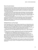
That way, each connector will have its own GND (left) and +5V (right) leads, as shown in Figure 7-3 and
Figure 7-4
Figure 7-3. Pin assignments for male header connections to sensors
104
CHAPTER 7 ONLINE THERMOMETER
Figure 7-4. Connections for +5V and GND to headers on shield
Connect Data Lines
Trim off a few short pieces of single-core cable and use it to link the center (data) pin of each connector
to the matching digital I/O line. The assignments we used are as follows:
sensor A = digital 3
sensor B = digital 4
sensor C = digital 5
sensor D = digital 6
sensor E = digital 7
sensor F = digital 8
Notice that we skipped the first few pins and started at digital pin 3. Pins 0 and 1 are used for the
serial connection (USB) to the host, and pin 2 is used by the Ethernet shield itself to communicate with
the Arduino. Many shields use pin 2 because it’s a special pin associated with an interrupt on the
Arduino.
We installed each wire, in turn, by inserting it from the top of the shield into the center hole behind
the connector and bending the end across to join with the connector pin, then guiding the rest of the
wire to the appropriate digital connection, and finally soldering both ends from underneath the shield.
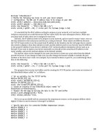
The result is shown in Figure 7-5.
105
CHAPTER 7 ONLINE THERMOMETER
Figure 7-5. Connections to digital I/O lines from center pin of each connector
That’s it for the shield setup. Notice that nothing we’ve done so far is actually specific to the
DS18B20 sensors: in fact, all we’ve done is create an Ethernet shield with connectors that each provide
power, ground, and access to one digital I/O line each. That makes this shield quite useful for a range of
things, such as plugging in other types of sensors or controlling devices if you provide appropriate
external buffering. By modifying the code, you could even have a mix of DS18B20s and other devices all
connected at once.
Assemble Sensors
Most of your sensors will be on long leads so they can be placed in interesting spots, but to test the
system on the bench we’ll fit a DS18B20 directly to a connector so it can be plugged straight into the
shield.
Each DS18B20 needs a 4k7 resistor between the data and +5V pins, so for the first sensor that will be
plugged directly into the board we’ll fit the sensor to the connector and solder the resistor to the sensor
leads.
It’s important to solder on the contacts the right way around because they only fit into the
connector body one way, and it has to align with the pin assignments on the shield. Lay the sensor
facedown on your workbench and fit the contacts so that the open side is up. Be careful to fit each one at
the same position on the pin because they need to line up when they slide into the connector body.
106
CHAPTER 7 ONLINE THERMOMETER
Figure 7-6. Pinout for DS18B20 temperature sensor
Bend one leg of a 4k7 resistor back around so it’s parallel to the other leg, then cut them off about
5mm from the resistor body and bend them slightly sideways.
Solder the resistor across the data and +5V leads on the temperature sensor using the pinout in
Figure 7-6 as a guide, and finally slide the contacts into the connector body to have a fully assembled
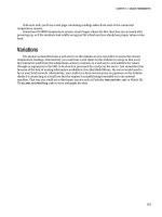
sensor as shown in Figure 7-7.
Figure 7-7. Sensor and resistor soldered to female connector
Plug the sensor into the shield and you’re ready to load the example program and test that it works.
To assemble other sensors on longer leads you can use pretty much any wire you want. Twisted pair
cable such as Ethernet cable works very well, and for shorter runs stereo shielded cable with the shield
connected to ground and the two internal conductors connected up with to data and +5V should work
well. Just be careful of very long runs with shielded cable because the shield can produce capacitance on
107
CHAPTER 7 ONLINE THERMOMETER
the line that interferes with digital data transmission. That shouldn't be a problem for typical cable runs
within a house at a low data rate but it's something to keep in mind for future reference.
We also fitted the 4k7 resistors into the back of the connector so all that’s needed at the other end is
the sensor itself.
If your sensor is going to be installed in an inhospitable environment you might want to smear
silicon on the leads and connections, being careful to leave most of the sensor body exposed so it will
pick up environmental temperature changes quickly.
For our particular application we wanted to fit the Arduino and shield into a protective case and still
be able to easily connect and disconnect sensors. We used a heavy-duty environmental protection case
and fitted it with DIN-rail mounting clips so it could be fitted in place with other electrical equipment in
a home automation system, and fitted inexpensive 3.5mm stereo sockets to the case with a small wiring
loom linking them to the PCB-mount connectors. We cut holes in the side of the case and fitted the
Arduino and shield into it so that the USB, power, and Ethernet sockets are accessible on one side, and
used DIY Power over Ethernet (PoE) to supply power to the system through the Ethernet cable.
More information about this particular home automation system and how Arduino is being used in
it is available at www.superhouse.tv.
Load Program
The example program for this project runs your Arduino as a simple web server that responds to web
requests with a page containing the current sensor readings. The program can be modified to change the
format of the web page that is sent, but before getting into the details of the code there are a few
limitations you should be aware of.
Because this program is based on the etherShield library for nuElectronics and Seeed Studio
Ethernet Shields, it doesn’t implement a full TCP/IP stack. One of the major limitations is that the
etherShield library doesn’t support packet fragmentation, which means the size of the response that can
be sent is strictly limited. A full TCP/IP implementation breaks up large messages into packets, each of
which is transmitted independently across the network and reassembled at the other end to reconstruct
the complete message. Packets are, as a major generalization, limited to between 64 and 1518 bytes in
size including all the headers. Because the TCP/IP header and the checksum eat into that you actually
end up with somewhat less than 1518 bytes as the upper size.
The upshot of this is that the entire web page that you send back has to fit within a single packet or
things simply won’t work, but what exactly is meant by “a single packet” depends a little on how your
local network is set up so we can’t give a definitive answer as to how many bytes it has to be. The
example program limits the TCP buffer to 500 bytes, but you can experiment with other values if you
like.
The other limitation is that the etherShield library doesn’t have any provision for specifying a
gateway or netmask, so it has no concept of routing. You can’t configure a gateway address in your
program and have it initiate a TCP/IP connection to a host outside your network because it simply won’t
understand where to send the packet. Note, however, that you can have it respond to requests from
outside your network if your gateway does source-NAT (network address translation), because as far as
the Arduino is concerned the request came from the gateway, which it thinks is just another host on your
network. It will reply to it on the LAN, and the gateway can then forward the response packet back to the
actual requesting client out on the Internet. TCP/IP networking is a huge topic, though, so we can’t go
into it in detail here.
So, on to the example program. It’s quite long for an Arduino program because so much of the
TCP/IP detail is exposed in the program itself.
First, it includes the etherShield library, then sets some variables to define the networking
configuration.
108