Practical Arduino Cool Projects for Open Source Hardware- P16 pptx
Bạn đang xem bản rút gọn của tài liệu. Xem và tải ngay bản đầy đủ của tài liệu tại đây (215.51 KB, 10 trang )
CHAPTER 8 TOUCH CONTROL PANEL
coordinates to control a 3D cube visualization. Processing is the sister project to Arduino: while Arduino
is all about controlling physical events, Processing is all about visualization, image processing, and
representing events graphically. In fact the Arduino IDE is based on the Processing IDE, so if you’re
familiar with one, you’ll feel right at home with the other.
To run the 3D cube program you’ll need to download the latest version of Processing from
www.processing.org and install it on your computer. You can then download the sketch called
TouchCube from the project page on the Practical Arduino web site.
Processing programs follow a very similar structure to Arduino programs. They have a setup()
function at the start that is called first, just as in Arduino, but rather than having a main program loop
called loop(), it’s called draw() in Processing.
The first thing the TouchCube program does is include the serial port class and create an instance
called myPort.
import processing.serial.*;
Serial myPort;
Then we set up variables for storing values from the Arduino and the current camera position.
int touchX; // The X coordinate value received from the serial port
int touchY; // The Y coordinate value received from the serial port
float xPos = 512; // Current camera X-axis position
float yPos = 512; // Current camera Y-axis position
The setup function determines how big the window should be for the visualization using the size()
function, sets the background fill color, and then opens the serial port to wait for values sent by the
Arduino.
One critical part of this setup function is the line right at the end that tells the serial port object to
buffer (store) all values it receives until it gets a newline. We’ll get back to that in just a moment.
void setup()
{
size( 800, 600, P3D );
fill( 204, 104, 0 );
myPort = new Serial(this, Serial.list()[0], 38400);
myPort.bufferUntil('\n');
}
The main program loop, called draw(), doesn’t need to do anything in this case because everything
is done in an event handler. We still need to declare it though.
void draw() {
// Nothing to do here!
}
This next section might seem a little bit like magic because we declare a function that isn’t called
from anywhere else in the code. However, the serial object uses this function as an event handler that is
automatically invoked when a certain thing happens. In this case, it’s called when the serial port has
buffered some input and then received a newline character as specified in the setup() function using
bufferUntil('\n'). When that occurs, the serialEvent() function is called and the serial port object (called
myPort) is passed into it so the event handler can process it.
129
CHAPTER 8 TOUCH CONTROL PANEL
Very cool, because it means the program can totally ignore the serial port until there is a value
waiting to be processed.
The first thing the event handler does is pull the characters currently in the serial buffer into a
variable called inString.
void serialEvent( Serial myPort )
{
String inString = myPort.readStringUntil( '\n' );
Then, if we’re happy that we were given a value and not just a lonesome newline character with no
other characters, we continue processing it. We also have to chop off any whitespace so we have just the
alphanumeric characters using the trim() function, as follows:
if( inString != null )
{
inString = trim( inString );
At this point we have a value that probably looks something like “32,874” stored in the variable, so
we need to split it apart on the comma delimiter and put the two resulting chunks into an array.
int[] coordinates = int( split( inString, ',' ) );
Finally, we have the X and Y coordinates separated out so we can do something with them.
Because a touch screen that is not being touched will return a very high or very low value on the 0–
1023 range, we chop off the ends of the range. That way we only update the value if the screen is being
touched, and leave it at its previous value if not.
touchX = coordinates[0];
if( touchX > 20 && touchX < 1000 ) {
When updating the coordinate, we apply some trickery to scale it out based on the size of the
window we created earlier. The map function takes an input variable and then two ranges: the first is the
acceptable range for the input, and the second is the required range for the output. What we’re doing
here is taking the touchX value and saying that it currently falls onto a scale between 0 and 1023, but
what we want to do is adjust it onto a scale between 0 and the width of the screen.
What that means is that if the touchX value is halfway along the 0–1023 scale (at, say, 511), the result
will be a value halfway along the 0–width scale. If width is 900, the result will, therefore, be 450.
xPos = map( touchX, 0, 1023, 0, width );
}
Then we do the exact same thing for the Y coordinate.
touchY = int( coordinates[1] );
if( touchY > 20 && touchY < 900 ) {
yPos = map( touchY, 0, 1023, 0, height );
}
We’re almost ready to draw the cube! The next section activates lighting on the window and sets the
background.
130
CHAPTER 8 TOUCH CONTROL PANEL
lights();
background( 51 );
Finally, we set the camera position based on the coordinates we extracted and then draw the actual
3D cube.
camera( xPos, yPos, 100.0, // eyeX, eyeY, eyeZ
0.0, 0.0, 0.0, // centerX, centerY, centerZ
0.0, 1.0, 0.0 ); // upX, upY, upZ
noStroke();
box( 150 );
stroke( 255 );
line( -100, 0, 0, 100, 0, 0 );
line( 0, -100, 0, 0, 100, 0 );
line( 0, 0, -100, 0, 0, 100 );
}
}
With your Arduino connected and running either the TouchscreenCoordinates or the
ReadTouchscreen sketches previously described to feed values through the serial port, and the
TouchCube program running on your computer to read them, you should be able to move your finger
around the Nintendo touch screen and see the view of the 3D cube change.
One little catch though: make sure you turn off the serial monitor in your Arduino IDE first.
Otherwise, Processing might not be able to open the port to receive the coordinates.
You might find the display jumps around a bit because it updates immediately every time it receives
a new coordinate. One approach to minimize this effect would be to use a small «FIFO» (First In, First
Out) buffer that holds perhaps the last three sets of coordinates and then average the values to set the
camera position.
Construct Hardware for Home Automation Control Panel
This project is quite straightforward in terms of both the software and the electronics. The tricky part is
entirely in the physical construction of the panel itself so that you end up with a professional end result.
Of course, the exact process will vary depending on what you will use as a mounting location so we can’t
give precise steps that will work for you, but the following principles should apply in most cases and will
help give you some inspiration for your own designs.
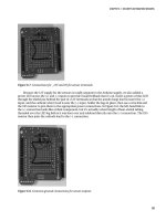
For our prototype we wanted to fit the touch panel into a standard blank electrical wall plate with a
printed background. The Nintendo DS touch screen just barely fits within the plate dimensions, so we
sat the touch screen on top, marked around the edges with a fine felt-tip pen, then carefully cut out the
center with a hacksaw to provide a neat clearance area just barely larger than the touch screen (see
Figure 8-6).
131
CHAPTER 8 TOUCH CONTROL PANEL
Figure 8-6. Wall plate with hole cut for touch screen
The offcut piece was then trimmed to fit snugly into the resulting hole and a slot was cut to allow the
touch screen connection tab to pass through. The pieces were then assembled upside down by placing
the touch screen facedown on a smooth surface, sitting the plastic insert on top of it, fitting the modified
faceplate over the whole lot, and pushing it down flush with the front of the touch screen.
This caused the plastic insert to be recessed several millimeters into the faceplate, just perfectly
aligned to hold the touch screen in place. Two-part epoxy glue was then run in a bead along two of the
edges to attach the insert to the faceplate, and it was left to sit undisturbed while the glue cured.
The result is a faceplate with the front panel recessed just enough for the touch screen to be set in
front of it, plus a slot for the connection tab to pass through to the rear of the panel (see Figure 8-7).
Figure 8-7. Wall plate with removed piece glued back in place behind its original location
132
CHAPTER 8 TOUCH CONTROL PANEL
Next you need to decide what “buttons” you will display behind the touch screen, if any. For a really
sleek look you can leave the touch screen totally blank and just use it as a large “touch on, touch off”
button. You can even combine this with gesture recognition, such as sliding your finger up/down to
increase/decrease volume or brightness of something you’re controlling. If you have electrically
operated drapes you could use slide detection to control them: slide up to open the drapes, slide down
to close them.
With a bit of work you can even implement detection of things such as a circular motion similar to
the scroll wheel on an iPod: clockwise to increase volume or brightness, counterclockwise to decrease.
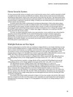
We created a simple graphic to go behind the touch screen to show the location of “hot zones,”
which act as virtual buttons. This is placed on the wall plate and the touch screen is then laid on top. The
graphic can be printed on a self-adhesive sheet and stuck in place to prevent it moving if you prefer.
The areas designated on our prototype were on/off for an exhaust fan, open/closed for electrically
operated drapes, and a slide bar for controlling lighting intensity (see Figure 8-8).
Figure 8-8. Touch control panel with button graphics mounted behind the touch surface
The background isn’t limited to just static elements, either. You could drill holes through the back
panel and mount LEDs to display the current status of the item being controlled, or cut a rectangular
hole and mount 7-segment LED or even LCD modules inside the panel.
If you don’t expect to ever change the graphic overlay you could glue the touch screen in place with
epoxy resin or similar, using a toothpick to apply a tiny amount along the edges where it won’t be seen.
An alternative is to use a piece of self-adhesive vinyl. Cut a rectangle out of the center, slightly
smaller than the touch screen, and stick it over the top so that it overlaps the panel. Then trim it around
the edges so it forms a neat border.
133
CHAPTER 8 TOUCH CONTROL PANEL
Calibrate Hot Zones
Connect your newly constructed touch control panel to your Arduino, plug in the USB connection to
your computer, and run the example code previously described. Open the serial monitor so you can see
the X and Y values being reported by the Arduino.
Draw a sketch of the layout of your buttons for reference, then use a stylus to touch the diagonally
opposite corners of each button in turn. Write down the X,Y values on your sketch. For our prototype we
printed an enlarged (150 percent) version of the background graphic and wrote the coordinates directly
on it (see Figure 8-9).
Figure 8-9. Calibrating touch control panel by noting X and Y coordinates for button regions
What you’ll end up with is a set of coordinates that define the bounds of each button. If you’re using
simple rectangular areas it’s pretty easy to then plot them into a table that shows the range of X and Y
values for each button (see Table 8-1).
134
CHAPTER 8 TOUCH CONTROL PANEL
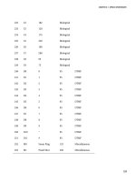
Table 8-1. Example X and Y coordinates for button regions
Button Xmin Xmax Ymin Ymax
Fan on 696 866 546 831
Fan off 696 866 208 476
Drapes open 420 577 540 866
Drapes close 420 577 208 476
You’ll notice that on our prototype the X and Y values don’t start from either the bottom left or top
left corner as you might expect: they start from the bottom right corner. This really doesn’t matter and is
easy to compensate for in software, and can also be adjusted by changing the connections to the touch
screen pins if necessary. In this case we could have changed the orientation by physically rotating the
whole wall plate by 180 degrees to put 0,0 at the top left. Regardless, it works perfectly well in any
orientation.
Having defined the button corner coordinates it should be fairly obvious what needs to be done in
software for the button hot zones: check the X and Y values and compare them to each defined range,
and if a match is found that button is considered to have been pressed. The slide control isn’t much
harder, and simply adds a response value proportional to the Y-axis position within the button.
The ReadTouchscreen example sketch included with the TouchScreen library is a good starting
point for a system to read button presses. All we have to do is extend the program by plugging the values
from the coordinate table into a series of comparisons to determine which button is being pressed.
#include <TouchScreen.h>
TouchScreen ts(3, 1, 0, 2);
void setup()
{
Serial.begin(38400);
}
void loop()
{
int coords[2];
ts.read(coords);
Serial.print(coords[0]);
Serial.print(",");
Serial.print(coords[1]);
if((coords[0] > 696) && (coords[0] < 866)
&& (coords[1] > 546) && (coords[1] < 831)) {
Serial.print(" Fan ON");
}
if((coords[0] > 696) && (coords[0] < 866)
135
CHAPTER 8 TOUCH CONTROL PANEL
&& (coords[1] > 208) && (coords[1] < 476)) {
Serial.print(" Fan OFF");
}
if((coords[0] > 420) && (coords[0] < 577)
&& (coords[1] > 540) && (coords[1] < 866)) {
Serial.print(" Drapes OPEN");
}
if((coords[0] > 420) && (coords[0] < 577)
&& (coords[1] > 208) && (coords[1] < 476)) {
Serial.print(" Drapes CLOSE");
}
if((coords[0] > 139) && (coords[0] < 327)
&& (coords[1] > 208) && (coords[1] < 866)) {
Serial.print(" Illumination:");
Serial.print(map(coords[1], 208, 866, 0, 100));
Serial.print("%");
}
Serial.println();
delay (1000);
}
As you can see the illumination slider reports not just that it is being pressed, but it also maps the Y
coordinate from the range of the slide area onto a range of 0 to 100 to determine the percentage
illumination to apply based on the position of the contact. Touching high on the slide scale will set the
illumination high, and touching it low will set it low.
There’s another improvement we can still make, which is to tweak the handling of the illumination
slider to provide larger areas at the top and bottom of the range for full-on and full-off. With the current
arrangement it would be very hard to turn the lights off entirely because if you touch near the bottom of
the slider it will still probably be at 4 or 5 percent illumination, while undershooting the contact area will
do nothing at all.
There are two ways to fix this problem. The first, and probably the most obvious, is to divide the
illumination slider into three separate zones so that it is treated as if it were three separate buttons. The
top section could map to a “lights on” response, the bottom to a “lights off” response, and the middle
remain as a variable illumination level.
We can also do it in a slightly more subtle way by making use of an obscure property of the map()
function to fudge the values at the top and bottom of the range. If you pass an input value to map() that
is outside the origin range—either lower than the bottom of the range or higher than the top of the
range—it returns a value that will exceed the destination range. We can, therefore, change the
illumination slider section of the previous code by increasing the bottom value and decreasing the top
value to shrink the range away from the ends of the hot zone, as follows:
if((coords[0] > 139) && (coords[0] < 327)
&& (coords[1] > 208) && (coords[1] < 866)) {
Serial.print(" Illumination:");
Serial.print(map(coords[1], 318, 756, 0, 100));
Serial.print("%");
}
136
CHAPTER 8 TOUCH CONTROL PANEL
137
It will then return negative values for contact right near the bottom of the range, and values greater
than 100 percent for contact right near the top of the range.
Negative values and readings greater than 100 percent obviously don’t make much sense, so next
t
he result needs to be constrained so it will be truncated to fit the desired range of 0 to 100. This is done
with the constrain() function that we can wrap around the map() function, as follows:
if((coords[0] > 139) && (coords[0] < 327)
&& (coords[1] > 208) && (coords[1] < 866)) {
Serial.print(" Illumination:");
Serial.print(constrain(map(coords[1], 318, 756, 0, 100), 0, 100));
Serial.print("%");
}
The complete version of this sketch, TouchControlPanel, i
s available for download from the project
page on the Practical Arduino web site.
It’s then a matter of deciding what you want the various buttons to do. You could control devices
directly using
outputs on the Arduino, or you could attach an Ethernet or WiFi shield and have it send
commands to a home automation system using web services
Just for fun we’ve also created a matching program written in Processing called
TouchContr
olPanelDisplay, also available for download from the project page. If you run
TouchControlPanel on your Arduino and TouchControlPanelDisplay on your computer you will see a
visual representation on your computer of the current state of the hot zones on the touch screen.
Mount Arduino
Because wall plates have very little clearance and you only need four analog inputs to read the touch
screen, this project works well with one of the small form-factor Arduino models such as the Pro Mini or
the Arduino Nano. Make sure the breakout board connecting to the touch screen is securely mounted to
prevent the connection ribbon from coming loose, and use short lengths of hookup wire to connect the
pads to the analog inputs on the Arduino. The rest of the installation we'll have to leave to your ingenuity
because you'll almost certainly have a different mounting location and requirements to us.