Practical Arduino Cool Projects for Open Source Hardware- P15 ppt
Bạn đang xem bản rút gọn của tài liệu. Xem và tải ngay bản đầy đủ của tài liệu tại đây (211.49 KB, 10 trang )
CHAPTER 7 ONLINE THERMOMETER
119
If all went well, you’ll see a web page containing readings taken from each of the connected
temperature sensors.
Sometimes DS18B20 temperature sensors return bogus values the first time they are accessed after
powering up, so if
the numbers look wildly wrong just hit refresh and you should see proper values come
back.
Variations
The project as described runs a web server on the Arduino so you can poll it to access the current
temperature readings. Alternatively, you could run a web client on the Arduino in a loop so that every
few minutes it reads from the temperature sensors, connects to a web server, and submits the values
through as arguments in the URL to be stored or processed by a script on the server. Just remember that
because of the lack of routing information available in the etherShield library, the server would need to
be on your local network. Alternatively, you could run a local reverse proxy as a gateway so the Arduino
thinks it’s connecting to a local host but the request is actually being forwarded on to an external
machine. That way you could use a third-party service such as Pachube (www.pachube.com) or Watch My
Thing (www.watchmything.com) to store and graph the data.
C H A P T E R 8
Touch Control Panel
Small four-wire resistive touch screens are now amazingly inexpensive: they are produced in such
enormous quantities for mobile phones, PDAs, and particularly handheld games such as the Nintendo
DS that they can be bought brand new for under US $10.
Larger touch screens are also rapidly falling in price. The popularity of netbooks with screens
between 7 and 10 inches in size has resulted in a healthy market for touch screens that can be retrofitted
to them and plugged into an internal USB port. Despite the fact that they come with control electronics
and a USB interface, those screens are also predominantly four-wire resistive devices, so if you dump the
control module that comes with them and interface to the screen directly you can have a 10-inch touch
screen on your Arduino! And if you want to go even bigger, there are often 15-inch, 17-inch, and 19-inch
touch screen kits available on eBay for under $150.
Note, however, that what is advertised as a “touch screen” is not actually a complete screen
including an LCD. It’s just the transparent glass and plastic panel that fits onto the front of an
appropriately sized LCD so the CPU can detect the coordinates at which the screen is being touched. If
you want your Arduino to display information on a screen and let you select or control it by touch, you’ll
have to do a bit more work to set up the LCD that goes behind the touch screen overlay.
Even on its own, though, a touch screen is a very handy device. They’re very thin and can be
mounted over the top of any flat surface, not just an LCD, so they’re great for creating little custom
control panels with the “buttons” printed on a sheet that goes behind the touch screen. All you have to
do is map the buttons to X/Y coordinates and your Arduino can figure out which button is being pressed
by matching the coordinates. Of course, your control panel could represent anything, not just buttons.
You could have a slider on it to select volume or temperature level by touching somewhere along a scale,
or it could be a plan of a house so you can control lights in different rooms by touching the correct part
of the floor plan.
In this project, we mount a Nintendo DS touch screen on a blank electrical wall plate to create a
touch-sensitive control panel that can link to a home automation system. The techniques we describe
here should work with pretty much any four-wire resistive touch screen available, but note that some
touch screens are also made using other technologies, such as capacitive and infrared, so make sure the
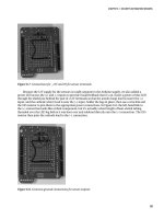
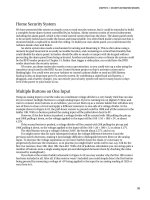
screen you buy is definitely a resistive model. The required parts are shown in Figure 8-1, and the
schematic is in Figure 8-2.
121
CHAPTER 8 TOUCH CONTROL PANEL
Figure 8-1. Parts required for connecting a resistive touch screen
Parts Required
1 Arduino Duemilanove, Mini, Pro Mini, or equivalent
1 Nintendo DS touch screen
1 Nintendo DS touch screen breakout board
1 Blank electrical wall plate
1 4-pin male breakaway header
Source code available from www.practicalarduino.com/projects/touch-control-panel.
122
CHAPTER 8 TOUCH CONTROL PANEL
Figure 8-2. Schematic for connection of resistive touch screen
Instructions
Reading a resistive touch screen accurately is not quite as straightforward as it first sounds because,
despite what you may have read online in various Arduino forums and blogs, they don’t have specific
output connections for X and Y values. You can’t read both the X and Y axis simultaneously: you have to
set up the pins in one configuration to read the X value, and change them to another configuration to
read the Y value. In practice, this can be done so fast that there is no way the user can tell you’re not
reading both the X and the Y value at the same time.
Once you understand the physical structure of a touch screen you’ll realize why they don’t have
simple connections for power, ground, X, and Y, as many people claim.
How Resistive Touch Screens Work
A resistive touch screen consists of several plastic layers built on a glass substrate that provides rigidity to
the whole structure. In front of this substrate is a thin plastic layer coated with a resistive material. In
some touch screens the resistive material is applied directly to the glass substrate to achieve the same
end result. In front of this is a layer of microdots, which are tiny spacers laid over the surface to support a
second thin plastic layer, also coated with resistive material (see Figure 8-3).
123
CHAPTER 8 TOUCH CONTROL PANEL
Figure 8-3. Layers in a resistive touch screen
When the screen is not being touched, the microdots hold the two resistive layers apart to cause it to
be an open circuit. When the front layer is touched, it distorts and makes contact with the back layer,
allowing electricity to conduct from one layer to the other.
Each of the four sides of the touch screen contains a conductive electrode that runs the whole
length of the edge and connects to the resistive surface on either the top or bottom layer matched up by
axis. For example, the left and right edges may connect to the front layer, while the top and bottom edges
connect to the back layer (see Figure 8-4).
Figure 8-4. X and Y axis electrodes inside a resistive touch screen
124
CHAPTER 8 TOUCH CONTROL PANEL
Those four edges are then brought out onto the touch screen connector as X1, X2, Y1, and Y2,
although the order on the connector may vary depending on the particular brand and model of touch
screen. If you have a touch screen with no datasheet available for it, you can figure out the pairs of
connections by measuring the resistance between them with a multimeter while the screen is not being
touched. Each matching pair will have a resistance between them of somewhere around 1K or lower,
while nonmatching electrodes will be open-circuit.
To read one axis of contact with the screen, one of the layers is connected to GND on one edge and
+5V on the other edge to provide a continuously varying voltage across the surface of that layer. One of
the edges on the other layer is then read using an analog input to determine the relative position of the
contact between the two edges: if it’s closer to the GND edge, the reading will be a lower voltage; and if
it’s closer to the +5V edge, the reading will be a higher voltage. When doing this the pins connected to
one layer need to be configured as digital outputs and driven to GND and +5V to power up that layer,
while one of the pins connected to the other layer needs to be configured as an analog input to read the
touch value.
Reading the other axis then requires switching around the connections so that the layer previously
being used for analog input now has GND and +5V applied across it, and one edge of the layer previously
providing power is switched to being an analog input so the value can be read from it.
This is all pretty easy on an Arduino because the analog input pins are actually also general-purpose
digital I/O pins, and their mode can be switched in software as required. We don’t need to waste time
and I/O lines externally switching the touch screen connections between an analog input and GND or
+5V. By connecting the X1, X2, Y1, and Y2 lines of a touch screen directly to four analog input pins, we
can then use software to switch pin modes between readings and use them as digital outputs to provide
GND and +5V to whichever layer needs it at the time.
On a Nintendo DS touch screen, the connector brings out the edges in order as Y1, X2, Y2, and X1.
To keep the physical connections as simple as possible, we’ll maintain that physical order and connect
those to analog inputs A0 through A3, respectively, as follows:
Y1 to A0
X2 to A1
Y2 to A2
X1 to A3
A minimal Arduino program that just reads and returns the values is fairly simple and helps explain
how the touch screen works. Before getting into the details of the project, we’ll look at a sketch that reads
values from the touch screen five times per second and reports the values to a computer via the USB
connection.
We start by defining variables to hold the values as read from the screen, as follows:
int xVal = 0;
int yVal = 0;
Next, we set up the serial connection to the host computer so we can report the X and Y values, as
follows:
void setup()
{
Serial.begin(38400);
Serial.println("Starting up touch screen reader");
}
The main program loop reads the X and then the Y value each time through. Reading the X value
involves setting up the Y-axis analog input pins as digital outputs and then doing an analog read. One
125
CHAPTER 8 TOUCH CONTROL PANEL
optional step we’re doing here is waiting for 2ms after setting up the outputs so the voltages have time to
settle. The Arduino’s analog inputs are very sensitive to eddy currents and induced voltages nearby, and
switching outputs immediately adjacent to an analog input can cause it to give spurious readings.
Adding a delay of a couple of milliseconds allows the input to settle down and returns a more consistent
reading.
void loop()
{
pinMode( 15, INPUT ); // Analog pin 1
pinMode( 17, INPUT ); // Analog pin 3
pinMode( 14, OUTPUT ); // Analog pin 0
digitalWrite( 14, LOW ); // Use analog pin 0 as a GND connection
pinMode( 16, OUTPUT ); // Analog pin 2
digitalWrite( 16, HIGH ); // Use analog pin 2 as a +5V connection
delay(2); // Wait for voltage to settle
xVal = analogRead( 1 ); // Read the X value
At this point we have the X-axis value, but not yet the Y-axis value. Next we need to switch around
the pin modes to do the same thing for the Y axis.
pinMode( 14, INPUT ); // Analog pin 0
pinMode( 16, INPUT ); // Analog pin 2
pinMode( 15, OUTPUT ); // Analog pin 1
digitalWrite( 15, LOW ); // Use analog pin 1 as a GND connection
pinMode( 17, OUTPUT ); // Analog pin 3
digitalWrite( 17, HIGH ); // Use analog pin 3 as a +5V connection
delay(2); // Wait for voltage to settle
yVal = analogRead( 0 ); // Read the Y value
We now have both the X- and Y-axis values, so finally we report them back to the host computer via
the USB connection and then wait a little while before doing it all over again, as follows:
Serial.print(xVal);
Serial.print(",");
Serial.println(yVal);
delay (200);
}
That’s it! Not so hard really when you understand what’s going on.
The complete source code for this sketch is available from the project page on the Practical Arduino
web site, and is called TouchscreenCoordinates.
Basic Touch Screen Connection Test
Touch screen connections are generally a very thin plastic ribbon with flexible metal strips attached to it.
By far the easiest way to connect to them is to use a breakout board with a connector mounted on it to
clip the ribbon into place. The example in Figure 8-5 is from SparkFun, and has a retention clip to lock
the ribbon into the connector. Before the ribbon can be inserted, the locking clip needs to be released by
126
CHAPTER 8 TOUCH CONTROL PANEL
sliding it toward the direction of the ribbon, which you can then insert before sliding the clip back again.
It’s a very delicate operation, though, and the locking clip is small and easily broken, so be careful when
sliding the clip in and out.
Another thing to watch is the thickness of the ribbon on the touch screen. The connector is designed
to firmly grasp a ribbon of 0.3mm thickness, but a bare touch screen ribbon is only about 0.1mm thick
and will pull straight out of the connecter unless it has a shim of some kind to make it thicker. For some
reason, touch screens seem to be supplied either with or without a shim attached and you never know
what you’re going to get. One of the touch screens we used for our prototypes had a tiny mylar shim
attached to the back of the ribbon, while the other one didn’t and needed a little piece of electrical tape
applied to the back to make the ribbon thick enough to lock into the clip.
You can solder hookup wire or ribbon cable to the breakout board if you like, or you can solder a 4-
pin male header to it so you can plug it straight into a breadboard or an Arduino.
The SparkFun breakout board brings the touch screen pins out in the same order as the touch
screen ribbon, which is Y1, X2, Y2, and X1. The example code previously shown also uses this order, so
for a basic connection test you can plug it straight into analog inputs 0 through 3.
Figure 8-5 shows a Nintendo DS touch screen connected to an Arduino Pro using a SparkFun
breakout board. Note that in this picture the touch screen is upside down, To access the touch surface, it
would be folded back over the top of the Arduino.
Figure 8-5. Nintendo DS touch screen connected to Arduino Pro via a SparkFun breakout board with male
headers soldered on
127
CHAPTER 8 TOUCH CONTROL PANEL
Plugging directly into the Arduino probably isn’t very convenient, so a short extension cable
consisting of a four-core strip of ribbon cable with a male header on one end and a female header on the
other can be a handy thing to have on hand.
To test out the touch screen, connect it to your Arduino, then load the previous example sketch in
the Arduino IDE, compile it, and upload it to the Arduino. Then activate the serial monitor in the IDE
and make sure it’s set to 38400bps so you can see the values being reported by the Arduino as you touch
different parts of the touch screen. Try moving your finger or a stylus around on the screen to see how
one value changes if you move along one axis, and the other value changes with the other axis.
If it seems like the touch screen isn’t working, make sure you’re using the correct side—it can be
hard to tell sometimes! The back has a feel like hard glass, while the front (sensitive) side is coated with a
plastic film that will feel softer.
Arduino TouchScreen Library
The previous sketch is a great way to understand how touch screens work and how to interface with
them, but the sections of code that twiddle the analog pins are a bit painful and repetitive. To make it
even easier to write programs that use touch screens, we’ve created an Arduino library that abstracts all
the details away for you. The library is called TouchScreen, and you can find a link to it on the project
page on the Practical Arduino web site.
Once you’ve downloaded and installed the TouchScreen library, you can access the screen with an
even simpler sketch that is included in the library as an example. In the Arduino IDE, go to File ->
Sketchbook -> Examples -> Library-TouchScreen -> ReadTouchscreen to load it up. That example
provides the exact same functionality as the program we just looked at, but is far more concise.
#include <TouchScreen.h>
TouchScreen ts(3, 1, 0, 2);
void setup()
{
Serial.begin(38400);
}
void loop()
{
int coords[2];
ts.Read(coords);
Serial.print(coords[0]);
Serial.print(",");
Serial.println(coords[1]);
delay (200);
}
Much neater!
A full explanation of how the TouchScreen library was written is included in the section “Writing an
Arduino Library” in Chapter 16.
Controlling a “Processing” Program
Seeing raw numbers come back to you on the screen is only interesting for about 20 seconds, so to do
something more visual, we’ve written a simple demonstration program in Processing to use those
128