Practical Arduino Cool Projects for Open Source Hardware- P24 pptx
Bạn đang xem bản rút gọn của tài liệu. Xem và tải ngay bản đầy đủ của tài liệu tại đây (268.22 KB, 10 trang )
C H A P T E R 12
Water Tank Depth Sensor
Water is a precious resource in many parts of the world and many people rely on water tanks to
supplement their water supply by storing collected rainwater or water pumped from a well or bore. But
how do you measure how full a tank is? Tanks are constructed of opaque material to prevent algae
growth and are often kept closed up to prevent mosquito infestation or access by rodents, so it’s
inconvenient to physically look inside. And besides, having a way to measure tank depth electronically
opens up a world of possibilities, such as automatic control of pumps to fill tanks when they get low or to
disable irrigation systems when not enough water is available.
The obvious way to measure tank depth is by placing a series of conductive pickups at various
heights inside the tank and measure the resistance between them. For example, you could attach ten
exposed terminals at equal intervals on a length of material such as PVC tubing, and insert it into a tank
vertically to measure the depth in 10 percent increments simply by reading the resistance between the
bottom terminal and each of the terminals above it. The downside to this approach, though, is that you’ll
need to do a lot of wiring and you’ll also need to read an analog input for every individual terminal. Also
keep in mind that most Arduino designs have no more than six analog inputs. There are ways around
this, such as using a resistor ladder, but it can still end up being quite time-consuming and still give very
poor resolution.
This project works a little differently. It uses a device called a pressure transducer to measure the
water pressure at the bottom of the tank, and from that measurement it calculates how full the tank is.
Water pressure increases by about 9.8kPa per meter of depth (varying slightly depending on the purity of
the water and other factors), so a full tank 1.5 meters tall will have a pressure at the bottom of about
14.7kPa above ambient atmospheric pressure. The “above ambient atmospheric pressure” part is
important: it’s not enough to simply measure the pressure at the bottom of the tank using a single-
ended “absolute” pressure transducer because varying climate conditions will alter the reading as the air
pressure changes. That’s why this project uses a “differential” pressure transducer that has two inlets. By
leaving one inlet open to the atmosphere and connecting the other to the bottom of the tank, the
transducer will output the difference between the two. This approach provides automatic compensation
for varying air pressure and giving a constant reading for constant depth even if the weather changes.
The Arduino then reads the output of the transducer and reports the depth of the tank.
In this project we will use an Ethernet shield so the Arduino can connect to an online datalogging
service called Pachube (www.pachube.com) to generate graphs of water depth over time, but you could
also have it make decisions based on water depth to control items such as a water pump or irrigation
system solenoid. You can see the required parts in Figure 12-1 and the complete schematic in Figure
12-2.
209
CHAPTER 12 WATER TANK DEPTH SENSOR
Parts Required
1 Arduino Duemilanove, Arduino Pro, Seeeduino, or equivalent
1 Ethernet shield or WiShield
1 Prototyping shield
1 MPX2010DP or MPX2053DP differential pressure transducer (see text)
1 LM324 op-amp
1 14-pin IC socket
4 1K resistors
3 22K resistors
1 1K multiturn variable resistor
1 10K multiturn variable resistor
2 10nF MKT capacitors (typically marked “103”)
1 100nF MKT capacitor (typically marked “104”)
10cm of 4mm tubing (commonly used for aquarium air pumps)
3 4mm internal-diameter cable glands (typically sold as “3 to 6.5mm”)
1 small weatherproof PVC box (we used 64mm × 58mm × 35mm)
1 medium weatherproof PVC box with O-ring seal (we used 115mm × 90mm ×
55mm)
2 meters flexible four-conductor wire (such as security cable or telephone wire)
Source code available from www.practicalarduino.com/projects/water-tank-depth-sensor.
210
CHAPTER 12 WATER TANK DEPTH SENSOR
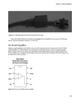
Figure 12-1. Parts required for water tank depth sensor
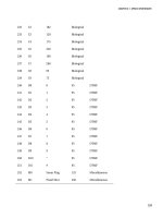
Figure 12-2. Schematic of water tank depth sensor
211
CHAPTER 12 WATER TANK DEPTH SENSOR
Instructions
If you come from a software background and haven’t done much work with electronics before, this
circuit can look a little intimidating, particularly as it deals with analog voltage levels rather than nice,
neat, “on or off” digital levels.
The key to understanding the circuit is to temporarily ignore the section in the top right of the
schematic shown in Figure 12-2 and just look at the overall symmetry of the central section, starting
from the MPX2010DP differential pressure transducer on the left.
Before getting into the details, though, you need to consider the requirements for the pressure
transducer. The MPX2010DP is fairly commonly available, but is only rated to 10kPa, equivalent to the
pressure from just over a meter of water depth. In testing we’ve used it in tanks up to two meters deep
and it’s performed fine, but keep in mind that doing so is pushing the transducer beyond the
manufacturer’s specifications, and if you need to measure depth of a larger tank you may need to use a
part with a higher pressure rating. For example, at the high end of the scale, the MPX2053DP is a similar
part that is rated to 50kPa—equivalent to 5m of water depth.
The transducer has two ports protruding from it and will generate a tiny voltage differential between
its outputs that is proportional to the difference in pressure between those ports. If the pressure applied
to both ports is the same, the sensor will remain in equilibrium and the voltage on both outputs will be
about half of the supply voltage, or about 2.5V in our case. The difference between them will, therefore,
be zero. If the pressure applied to port 1 is higher than the pressure applied to port 2, the voltage on pin
2 will rise and the voltage on pin 4 will fall. The variation is tiny, though: a pressure differential of 10kPa
will cause a voltage differential of only about 12.5mV.
That’s too small to be measured reliably by an analog input on an Arduino, so the rest of the circuit
is dedicated to amplifying that voltage differential up to a higher level.
The two transducer outputs are fed into the inputs of “operational amplifiers,” more commonly
referred to simply as “op-amps.” Op-amps are perhaps one of the most commonly manufactured
nonpassive electronic devices ever, and they work by taking the difference between two inputs and
outputting a signal that is an amplification of that difference. As such, we could have just used a single
op-amp and fed both outputs from the transducer into it, but that wouldn’t have provided enough gain
to raise the signal to a level that the Arduino can read reliably. To overcome this we use a compound
amplifier circuit that amplifies each of the outputs individually, driving the high signal further above the
2.5V reference point and the low signal further below 2.5V. The result is that the voltage difference
between pins 1 and 7 on the outputs of op-amps 1 and 2 will be greater than the voltage difference
between the transducer outputs.
The combination of the 22K resistors and 10nF capacitors linking the output of op-amps 1 and 2
back to their inputs provide “negative feedback,” with a rise in output level decreasing the gain to
maintain stability. It helps the amplifier maintain a steady state and may look counterintuitive, but this
is a very common configuration for op-amps and you’ll see it in many analog circuits. For more
explanation of negative feedback op-amp circuits, see the Wikipedia page at
en.wikipedia.org/wiki/Operational_amplifier.The 1K multiturn variable resistor joining the negative op-
amp inputs together also controls the gain so that the overall effectiveness of the amplification circuit
can be altered to best suit the characteristics of the transducer. Most variable resistors are single-turn,
and adjust from 0R to their maximum rating through only about 270 degrees of rotation. That doesn’t
provide enough sensitivity when tuning an op-amp circuit, though, so we’ve specified multiturn variable
resistors that are commonly available in either 10-turn or 20-turn versions. Multiturn variable resistors
have a tiny threaded rod inside to gear down the turns you apply and provide very fine control of their
resistance.
The outputs from the op-amps in the center of the schematic shown in Figure 12-2 then pass
through a pair of 1K resistors and into the two inputs of op-amp 3, which once again amplifies the
difference to drive an even greater variation on its output on pin 8. The result is that tiny variations in
212
CHAPTER 12 WATER TANK DEPTH SENSOR
voltage across the transducer outputs on the extreme left of the circuit cause much larger voltage
variations at the output on the far right where it will be connected to an Arduino analog input.
That’s not quite the whole story, though. The section of the circuit we’ve been ignoring up in the top
right also comes into play, biasing the input on pin 12 of op-amp 4, which in turn biases the input on pin
10 of op-amp 3. When tuning the circuit, the 10K variable resistor is adjusted until the output of op-amp
4 at pin 14 is about 1V when the pressure difference on the transducer is zero. This provides a base level
of 1V to the Arduino input when the tank is empty.
Having set the bias for an empty reading, the 1K variable resistor controlling the gain on the first two
op-amps is adjusted until the output to the Arduino is about 3V when port 1 of the transducer is exposed
to the pressure at the bottom of a full tank. The circuit, therefore, has an output voltage that swings
linearly between about 1V for an empty tank and 3V for a full tank, a variation of 2V.
So why bother with the bias to pull the “empty” value up to 1V and limit the gain to set the full value
at 3V? Why not remove the “empty” bias and increase the amplification to provide a wider swing from 0V
to 5V on the output and take advantage of the full input range of the Arduino’s analog to digital
converters?
The reason is that the performance characteristics of an op-amp typically don’t allow it to provide a
full rail-to-rail swing, and even if they could do so the linearity of the output could be compromised
toward the edge of the range. Limiting it to a 1V-to-3V swing is well within the performance rating of the
LM324 op-amp we’re using, though, and avoids the non-linear regions toward the edges.
Looking at the schematic in Figure 12-2 you may be a little confused by the fact that it shows four
op-amps, while looking at the photos there is only one integrated circuit. That’s because the LM324 is a
quad package with four op-amps inside one physical chip, all sharing common power and ground
connections. Perfect for this application. What you see in the schematic is the logical representation of
the four op-amps contained in the package because as far as the circuit is concerned they are separate
devices. The fact that they’re in the same physical package is just extra convenience for us when it comes
to assembly.
Assemble the Shield
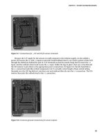
Begin by fitting the 14-pin IC socket, noting the direction of the orientation marker: the little notch in
one end. That notch indicates which end of the chip is pin 1, which in the photo shown in Figure 12-3 is
in the bottom right corner of the IC socket. The rest of the pins are numbered counterclockwise up the
right side to 7 in the top right, 8 in the top left, and down to 14 in the bottom left with the socket oriented
as shown in the photo. Note that this is rotated 180 degrees compared to most IC datasheets, which
typically show the orientation marker at the top with pin 1 on the top left. In this case, though, it made
sense to mount the chip upside down so the supporting parts are nearer the appropriate IC pins.
Next insert the resistors immediately adjacent to the socket, bending the leads underneath the
shield to form jumpers to adjacent pads where necessary. The pair of 10nF MKT capacitors (probably
marked “103K”) just to the right of the socket go in next, and then the resistors are mounted vertically
next to them. Then fit the 10K multiturn variable resistor on the left (marked “103”), and the 100nF MKT
capacitor next to it (marked “104K”) along with the jumpers that link them to ground and +5V. The 1K
multiturn variable resistor and associated links go on the right.
For convenience when assembling and testing the system we fitted a 4-pin oriented male header for
the cable to the pressure transducer. If you prefer, you can solder a lead for the transducer directly to the
board.
213
CHAPTER 12 WATER TANK DEPTH SENSOR
Figure 12-3. Parts assembled on shield ready for insertion of LM324 op-amp into the IC socket
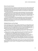
That’s all the hard assembly work done. The only thing left to do on the prototyping shield is to
install a jumper lead that connects pin 8 of the op-amp to analog input 0 on the Arduino. The 1K resistor
mounted on the end connected between pins 8 and 9 provides a very convenient mounting point for one
end of the jumper lead, which then stretches across the board to analog input 0. Connecting the op-amp
output to the analog input with a jumper lead like this makes it easy later if you want to switch to a
different input so you can stack multiple shields.
Finally, insert the LM324 op-amp into the socket. Inserting ICs can be tricky at first because the legs
always spread out wider than the holes in the socket. You can buy special tools for inserting ICs into
sockets but they’re really not necessary on a small IC like an LM234: it’s just as easy to bend the pins in a
little until they align with the holes in the socket. Try putting the IC down on your workbench on one
edge, grip it on the ends, and very carefully push down to bend the pins in. Turn the IC over and do the
same to the other side so it will fit into the socket neatly. Be cautious in applying pressure to the pins, but
don’t be afraid. The worst that can happen is you bend them too far and have to bend them back.
You’ll also notice a short link near the bottom left of the board to connect one of the LEDs provided
on this particular prototyping shield to ground. The other end of the LED is connected to +5V via a 1K
current-limiting resistor. That LED is included just to show when the shield is powered up and is entirely
optional, so it doesn’t appear in the circuit diagram.
214
CHAPTER 12 WATER TANK DEPTH SENSOR
Figure 12-4. Fully assembled tank depth sensor shield
Put the shield aside for a while and move on to assembling the sensor housing.
Determine Sensor Installation Method
Although the basic circuit will be the same regardless of how you mount it, this project has several
options regarding how you expose the transducer to the pressure at the bottom of the tank while also
exposing it to atmospheric pressure outside the tank. Before starting construction of the sensor
assembly you need to think about how it will be connected.
There are four basic options for installation. The first, and most obvious, is to fit the Arduino and
shield into a weatherproof case mounted just above the tank with one transducer hose exposed to the
atmosphere and the other running down inside the tank with a weight attached to hold it on the bottom
(see Figure 12-5). This can work in the short term but can cause problems over time due to diffusion of
air in the tube into the water in the tank. Eventually, the water level will rise up the hose with the result
that your Arduino will be reading the pressure from the height of the top of the water in the hose, not the
pressure at the bottom of the hose. If left in long enough, a full tank will appear to be slowly draining
until you get an “empty” reading. Of course, you can periodically pull the hose out of the tank and drain
it to restore accuracy, but it’s not really a good long-term solution.
215
CHAPTER 12 WATER TANK DEPTH SENSOR
Figure 12-5. Pressure transducer mounted above tank
The second option is to mount the entire Arduino and sensor inside a waterproof container
submerged at the bottom of the tank with a short hose exposed to the water and a long hose running up
and exiting the tank to provide an atmospheric pressure reference (see Figure 12-6). You’ll also need to
pass the power and data cabling up through the tank, and it goes without saying that electricity and
water don’t mix, so you need to be very careful to totally seal the assembly! Plastic project boxes with
waterproof O-ring seals are fairly commonly available, and combined with waterproof cable glands and
liberal doses of silicone sealant you should be able to build an assembly that can withstand long-term
submersion without problems. Getting access to the Arduino for maintenance, though, could be quite
tricky, and condensation in the atmospheric tube could build up over time.
216
CHAPTER 12 WATER TANK DEPTH SENSOR
Figure 12-6. Pressure transducer and Arduino mounted inside tank
The third option is a clever variation on the previous approach that replaces the project box with a
length of large-diameter pipe, sealed at one end and protruding from the bottom of the tank all the way
up out of the water, or alternatively, a sealed box with a pipe attached. An Arduino with two shields
stacked on top will slide easily into the end of a 75mm (3-inch) PVC pipe, and you can then pass a short
length of hose out through a cable gland to sample the water pressure near the bottom of the tank. A 2m
length of 75mm pipe can be inserted vertically into a tank with the top protruding, but be warned that it
will displace a surprisingly large volume of water and will be extremely buoyant, so you will need to
attach a significant weight to hold it down (see Figure 12-7).
You’ll also need to make sure the top isn’t directly exposed to the weather so the pipe fills up and
drowns your Arduino first time it rains! And you’ll be limited to using cabled Ethernet rather than WiFi
for communications because a WiFi shield surrounded by several tons of water will have no range at all.
Overall, though, this is a very practical way to do it and gives you reasonable access to the Arduino for
future maintenance, but watch for corrosion over time since air can circulate so easily all the way down
to the circuitry.
217
CHAPTER 12 WATER TANK DEPTH SENSOR
Figure 12-7. Pressure transducer and Arduino mounted in a pipe
The fourth option, and the one we recommend, is to mount the Arduino just outside the tank with a
short hose from the pressure transducer entering an attached pipe, such as the outlet (see Figure 12-8).
This is probably the safest way to go because you end up with no hose required at all to sample the
outside air, a very short hose to sample water pressure, and much less chance of your Arduino suddenly
turning into a submarine because you missed a spot with the silicone sealant. You retain excellent access
to the Arduino for maintenance, it’s not blocked by the mass of water so WiFi should still work well, and
by placing it all in a weatherproof enclosure you can minimize corrosion and other bad things that
happen to exposed electronics left outdoors.
The downside, though, is that this fitting method is much harder if your tank is already full of water.
You’ll need to drill a hole into the output pipe, and unless you do it on the outside of the stop valve you’ll
need to drain the tank first. Putting it on the outside of the valve isn’t a perfect solution either, though,
because you’ll get an empty reading whenever the valve is closed. If your tank is full and there’s no way
to fit the pressure sensor without draining it, you might have to resort to one of the mounting methods
described previously.
This is the mounting method we’ll describe in this project, though, because it’s definitely the safest
for your Arduino.
218