The Adobe Illustrator CS Wow- P12 potx
Bạn đang xem bản rút gọn của tài liệu. Xem và tải ngay bản đầy đủ của tài liệu tại đây (3.3 MB, 30 trang )
Scratchboard Art
Using Multiple Strokes, Effects, and Styles
Overview: Apply multiple strokes
to simple objects; offset strokes;
apply effects to strokes; create and
apply graphic styles.
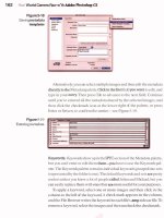
The original scratchboard art consists of simple
primitive shapes
To offset a path's Stroke from its Fill, select the
Stroke in the Appearance palette and apply Free
Distort and Transform from the Effect >Distort &
Transform menu
304 Chapter 9 Live Effects & Graphic Styles
Artist Ellen Papciak-Rose asked consultant Sandee Cohen
if there was a way to simulate scratchboard art in Illus-
trator. Cohen devised a way to transform Papciak-Rose's
artwork using Art Brushes, multiple strokes, and stroke
effects, which were then combined and saved as graphic
styles. Once a series of effects is saved as a graphic style,
you can easily apply that graphic style to multiple objects
to create a design theme. Art directors may find this
method helpful for unifying and stylizing illustrations
created by a number of different artists.
1 Applying Art Brushes and Fills. To create a more natu-
ral-looking stroke, Cohen applied Art Brushes to simple
objects supplied by Papciak-Rose. Cohen used Charcoal,
Fude, Dry Ink, Fire Ash, and Pencil Art Brushes (on the
Wow! CD). Select a simple object, then click on your
choice of Art Brush in the Brushes palette or in a Brush
Library. (For more on Art Brushes, see the Brushes chap-
ter.) Next, choose basic, solid fills for each object.
2 Offsetting a stroke. To develop a loose, sketchlike
look, Cohen offset some of the strokes from their fills.
First, highlight a stroke in the Appearance palette and
apply either Effect > Distort & Transform > Free Distort
or Effect > Distort & Transform > Transform to manually
or numerically adjust the position of the stroke so that it
separates from the fill. This gives the stroke the appear-
ance of a different shape without permanently changing
the path. (You can further reshape the stroke by double-
clicking the Transform attribute in the Appearance pal-
ette and adjusting the offset of the Stroke attribute.)
3 Adding more strokes to a single path. To add to the
sketchlike look, Cohen applied additional strokes to each
path. First, she chose a Stroke attribute in the Appearance
palette and clicked the Duplicate Selected Item icon at the
bottom of the palette. With the new Stroke copy selected,
she changed the color, as well as the choice of Art brush.
She also double-clicked the stroke's Distort & Transform
effect in the Appearance palette and changed the settings
to move the Stroke copy's position. Cohen repeated this
until she had as many strokes as she liked.
To make a stroke visible only outside its fill, make sure
that the object is still selected, and simply drag the stroke
below the Fill in the Appearance palette.
4 Working with graphic styles. To automate the styl-
ing of future illustrations, Cohen used the Appearance
and Graphic Styles palettes to create a library of graphic
styles. Whenever you create a set of strokes and fills you
like, click the New Graphic Style icon in the Graphic
Styles palette to create a new graphic style swatch.
Once Cohen had assembled a palette of graphic style
swatches, she could alter the look and feel of the artwork
by simply applying a variety of graphic styles to selected
paths. Using new colors sent by Papciak-Rose, Cohen's
graphic styles from an earlier scratchboard project were
re-colored to create the graphic styles used here. The use
of graphic styles allows the artist or designer to create a
number of overall themes in a graphic style library, and
then apply them selectively to illustrations or design ele-
ments. This work flow can also be used to keep a cohesive
look throughout a project or series.
This graphic illustrates the individual strokes that
Cohen combined to create the multiple strokes
for the face object in the final illustration
Multiple Strokes applied to an object shown in
the Appearance palette; appearance attributes
saved in the Graphic Styles palette by clicking
the New Graphic Style icon
Applying different graphic styles to objects can
give the same artwork several different looks
Chapter 9 Live Effects & Graphic Styles
305
Embossing Effects
Building an Embossed Graphic Style
Overview: Apply object-level effects
for highlights and shadows; build
appearances, save as graphic styles
and apply to layers.
At the top, making the screw slots (on the left,
the rectangle and on the right, the rectangle
with Round Corners Effect): at the bottom, an
enlarged view of the composite appearance
The Drop Shadow options pop-up dialog box;
edit the X and Y Offset fields to adjust the
position of the shadow and highlight (check the
Preview box to see the effect as you work)
Resizing appearances
If you plan to resize an Illustration
that contains appearances with
stroke values, be sure to apply
the appearances to objects, not
to layers. Illustrator may fail to
re-scale stroke values in layer-
targeted appearances.
Ted Alspach, Senior Product Manager for Adobe Illustra-
tor, choose the embossed letters, numbers and lines of
a license plate to demonstrate the ease and flexibility of
using Illustrator's effects and appearances. In this memo-
rial to French mathematician Pierre Bezier, inventor of
the original Bezier curve, Alspach simulated the look of
embossing by applying a drop shadow effect and by build-
ing a sophisticated graphic style.
1 Applying the drop shadow effect. Start the license
plate by drawing the background shape, circles, curves
and other linework. While technically not a raised sur-
face, the four screw slots still require highlights and
shadows to convey the impression of dimension. To cre-
ate a slot, draw a rectangle and then Fill with White and
Stroke with None. Use the Round Corners Effect (Effect >
Stylize > Round Corners) to give the object a more oval
shape. To cast the plate's shadow on the edge of the slot,
select the slot rectangle and apply the Drop Shadow Effect
(Effect >Stylize >Drop Shadow). In the Drop Shadow
dialog box, choose black for color, Blur 0, and Offset up
and to the left (using negative numbers for "X" and "Y"
offsets). Then click OK. Repeat the drop shadow effect to
make the highlight, except choose a light color and Off-
set down and to the right (using positive numbers). To
further tweak the drop shadows (modifying their color
or width, for example), simply double-click the attribute
name "drop shadow" in the Appearance palette (Win-
dow > Appearance) and edit the values in the dialog box.
306 Chapter 9 Live Effects & Graphic Styles
2 Building multiple appearances. Alspach took another
approach to embossing by building a sophisticated
graphic style in which transparency and multiple offset
strokes simulate highlights and shadows.
To make the license plate lettering, type the characters
in a sans serif font and convert them to outlines (Type >
Create Outlines). Ungroup the characters, select a char-
acter and set its Fill to orange. To make the first emboss-
ing highlight, select the orange Fill appearance attribute
in the Appearance palette (Window > Appearance) and
copy it by clicking the Duplicate Selected Item icon at the
bottom of the palette. Now, select the lower Fill attribute
in the palette, choose white from the Color palette and, in
the Transparency palette, set Opacity to 25% and blend-
ing mode to Screen. Then, choose Effect > Transform >
Distort & Transform to offset it up and to the left by edit-
ing the Move fields (negative Horizontal and positive Ver-
tical). Make two more copies of this white Fill attribute by
once again clicking the Duplicate Selected Item icon. Off-
set each copy farther up and to the left by double-clicking
the Fill's Transform attribute and editing the Move values
in the Transform dialog.
To start the shadows, first duplicate the lowest white
Fill. Now select the bottom white Fill and set its color to
black, Opacity to 50%, and blending mode to Multiply.
Double-click the Fill's Transform attribute and edit the
Move values to offset it down and to the right. Copy this
shadow and offset it farther down and to the right. When
you have finished, the Appearance palette will display six
Fill attributes for the object.
3 Creating and applying a graphic style. Alspach turned
the appearance set into a graphic style by dragging the
Appearance palette's preview icon and dropping it in the
Graphic Styles palette. He then applied the graphic style
to the layer with the number characters. You can achieve
the same embossing look by applying the graphic style to
selected character outlines or to a group composed of the
character outlines.
Appearance palette showing the appearance
preview icon (top left), and the target of the ap-
pearance (Object)
Move values in the Transform Effect dialog box
to offset Fill attribute up and left
Close-up view of the embossed letter characters
with the multiple highlight and shadow strokes
that progressively hide the background artwork
Chapter 9 Live Effects & Graphic Styles
307
Blurring The Lines
Photorealism with Blends and Effects
Overview: Trace a placed image;
draw objects and fill them with col-
ors sampled from the image; create
blends; rasterize objects and apply
Gaussian Blur.
The original composite photograph (made from
separate images in Photoshop) placed on a
template layer
All of the objects Brashear drew for the illustra-
tion, displayed in Outline View
Using a technique he calls "Pen and Eyedropper," artist
Bruce Brashear reproduces photographs in Illustrator
by tracing a placed image and filling objects with colors
sampled from the image (see Brashear's Vector Photos in
the Drawing & Coloring chapter to learn about this tech-
nique). In this illustration, Brashear expands his tech-
nique by employing blends and Gaussian blurs to capture
the subtleties of candlelight and reflections.
1 Placing an image, and drawing and coloring objects.
After beginning a new file, Brashear placed an image of
a candle and flame on a template layer (File >Place). He
traced the shapes for the candle, wick, flame and halo
using the Pen tool. For a complex object like the candle
flame or the candle wick, you may need to create several
objects or blends to completely illustrate its different col-
ors or shapes (Brashear created 11 objects for his candle
flame). To fill your objects with colors from the image on
the template layer, select the Eyedropper tool, select an
object, and Shift-click in the image to sample its color.
2 Making a halo from blends, rasterizing it, and apply-
ing a blur to it. Brashear's soft, round halo behind the
308
Chapter 9 Live Effects & Graphic Styles
flame was created with blends and several effects. To
begin a halo, draw at least two objects to blend (Brashear
made five objects to serve as transitional color blends
in the image's halo). Next, fill each object with a color
sampled from the placed image using the Eyedropper
tool. Then, select the objects and choose Object > Blend >
Make. To set the complexity of the multi-step blend that
Illustrator creates, choose Object >Blend > Blend Options
(or double-click the Blend tool icon in the Tools palette).
In the Blend Options dialog box, click the pop-up menu,
select Specified Steps and enter a high enough number
to provide a sufficient transition of shapes or colors (the
number you choose sets the steps between each pair of
objects, not the total steps for the whole multi-step blend).
If you need to reshape the halo, click on anchor points
with the Direct Selection tool and move the points or
their Bezier handles. Finish by drawing a background
rectangle and filling it with a color that will contrast with
the colors in the halo blend.
While blends can soften the shape and color transi-
tions between objects, you can further soften the appear-
ance of your halo by applying a Gaussian Blur. Because
applying a raster effect to a complex blend can tax your
computer's processor, consider rasterizing the blend
before applying the blur. (Note: because rasterizing art-
work will prevent it from being further edited, save a
copy of it in case you need it later.) To rasterize, select
the black background rectangle and the multi-step blend
you created previously and choose Object > Rasterize. In
the pop-up Rasterize dialog box, set Resolution to a value
that suits the size or medium of your illustration's display
or publication; also, set Anti-aliasing to None. Be sure to
review the Illustrator Basics chapter for guidance on set-
tings that affect the quality of exported Illustrator files
with raster objects and effects.
When you're ready to apply the blur, select the
rasterized object and choose Effect >Blur > Gaussian
Blur. In the Gaussian Blur dialog box, move the slider to
the right or enter a number in the Radius field (Brashear
The background and five halo objects (each halo
object shown here with magenta stroke for
demonstration)
The multistep blend with 12 blend steps be-
tween each of the five original component
objects
Above, the rasterized object created from the
multi-step blend; below, the Object >Rasterize
dialog box
Chapter 9 Live Effects & Graphic Styles
309
Top, the Gaussian Blur dialog box; bottom, the
rasterized object following blurring
The original yellow candle flame tip on the left;
on the right, the original flame tip and a copy
that was scaled smaller and filled with yellow-
white
On the left, an elongated copy of the original
candle flame tip in front of the yellow and white
tips; in the middle, the yellow and white tips are
blurred; on the right, the blurred flame tips after
being masked
applied a blur with a 20 pixel radius to his halo's blend).
If you want to change the blur later, simply select the
blurred object and double-click Gaussian Blur in the
Appearance palette, and enter another Radius value.
3 Blending, blurring and masking the flame. Brashear
observed that the orange tip of the flame in the photo-
graphic image was hard-edged along the sides but gradu-
ally blurred near the tip. You can achieve this visual effect
in Illustrator with a blur and a clipping mask. Start by
selecting the object you drew as a triangular flame tip.
Then select the Scale tool and click on the bottom-left
point of the tip, then click on a point or line on the other
side of the tip and drag inward while pressing the Option/
Alt key to create a smaller copy of the object. Fill the copy
with a yellow-white color. With the copied object still
selected, click on the bottom-left point with the Scale tool,
click on a point or line opposite it and Option-drag/Alt-
drag a new outline that is taller but not wider than the
other tip objects. Next, select the first two tip objects and
choose Effect > Blur > Gaussian Blur; in the pop-up Gauss-
ian Blur dialog box, set the Radius to 1.0 pixel. To finish,
select the blurred tips and the unblurred tip (the second
copy you made) and choose Object >Clipping Mask >
Make. As a result, the blur is confined to the edges of the
clipping mask (but spreads through the empty area at the
top of the masking object).
The two faces of Rasterize
When you apply Effect > Blur >Gaussian Blur to a vector
object, Illustrator automatically rasterizes the paths
"live" (using the parameters found in the Effect >
Document Raster Effects Settings dialog). This doesn't
happen with the Filter version of the Gaussian Blur,
however. You need to convert your vector object to a
raster object using Object > Rasterize before you can
apply the Gaussian Blur filter. Remember that unless
you undo the rasterization, your vector object will be
permanently changed to raster—so make a copy first!
310 Chapter 9 Live Effects & Graphic Styles
Ted Alspach
Ted Alspach used the
Flare tool to create an air
of mystery in this mock
movie poster. The Flare
tool simulates a lens flare
in a photograph by cre-
ating a halo, rays, and
rings around an object.
Alspach selected the Flare
tool (found in the Rect-
angle tool pop-up menu),
clicked and dragged to set
the halo size, then click-
dragged again to set the
distance and direction
of the rings, while using
the Arrow keys to adjust
the number of rings. He
colored some elements
(such as the type) a light
shade of gray to give the
flare an illusion of greater
brilliance. In addition to
the click-drag method,
components of the flare
can be modified using the
Flare Options dialog box.
Here, you can adjust the
diameter, opacity, and
brightness of the flare's
center, as well as the
fuzziness of the halo, the
number of rays, and the
flare's crispness.
Taking care of the Flare
The Flare tool is unusual in that it's the only tool that sometimes
requires a two-step process. When the "Rings" option is checked,
you must click-drag to establish the center, and then click or click-
drag again to determine the length and direction of the path
along which the rings are drawn. If "Rings" is unchecked, drawing
a Flare is a one-step process. Many people don't realize the de-
fault two-step process and click away onto something else before
completing their flare.
Chapter 9 Live Effects & Graphic Styles 311
Warps & Envelopes
Using Warping and Enveloping Effects
Making sure that the flag artwork is grouped.
Note: The Appearance palette shows informa-
tion for the currently targeted (not just selected
or highlighted) object in the Layers palette
The Flag Warp applied to a not-fully-grouped
flag artwork. The stripes are grouped, but the
stars and the union (blue field) are separate
objects
With Preview enabled, experiment with the
Warp Options settings
After the tragic events of September 11, 2001, consultant
Sandee Cohen wanted to make some flag decorations for
her Web site. She used Illustrator's Warping and Envelop-
ing effects to mold copies of a basic rectangular flag into a
waving flag and a bow tie.
Warps are the easier of the two methods to under-
stand and use. Simply choose one of the 15 preset shapes
from the Warp menu and adjust the shape using the
sliders in the Warp Options dialog box.
Envelopes let you use any path, warp preset, or mesh
object to shape and mold your artwork into almost any
form imaginable. You can further manipulate the shape
using the envelope's anchor points.
Although Warps and Envelopes leave original artwork
unchanged, only Warps can be saved as graphic styles.
1 Group clip art for use with Warp effects. Cohen
started with a standard United States flag from a clip art
collection. First, she made sure that the flag artwork was
a grouped object by selecting the flag artwork (which also
targets it in the Layers palette) and checking its descrip-
tion in the Appearance palette. If the artwork is not a
grouped object, then the effects will not be applied to the
artwork as a whole, but rather to each of the paths indi-
vidually (as shown in the sidebar).
2 Make a copy of the flag artwork and apply a Warp
effect. Next, Cohen made a duplicate copy of the flag by
312 Chapter 9 Live Effects & Graphic Styles
Overview: Group clip art for use
with Warp; apply Warp; save Warp
effect as a graphic style; apply Enve-
lope using a shaped path; add a shad-
ing effect using a mesh.
selecting it and, holding down Option/Alt, dragging it
to a position below the original. While the duplicate was
still selected, Cohen chose Effect > Warp > Flag to bring
up the Warp dialog. She enabled the Preview checkbox in
the Warp dialog box so she could preview the effect her
settings would have on the artwork. Cohen set the Hori-
zontal Bend slider to -42% to create the first stage of her
waving flag effect, and clicked OK to apply the Warp. She
then applied a second Warp effect to the flag artwork, to
complete her waving flag. With the artwork still selected,
she chose Effect > Warp > Arc and, with Preview enabled,
set the Horizontal Bend slider to 40%.
Note: In the Warp dialog box, you have access to the full
library of Warp shapes no matter which warp you chose
from the Effect > Warp menu. Simply click and drag on the
style pop-up menu in the Warp dialog box to access any of
the Warp shapes. As long as Preview is enabled, you can
then experiment with each Warp shape and settings to see
how each will affect your artwork before you apply one.
To remove a Warp effect, target your artwork. Then,
in the Appearance palette, select the Warp and either
click on, or drag your selection to, the Trash button.
3 Save your Warp effect as a graphic style. Once you
are pleased with a particular Warp effect or effects that
you have achieved, you can easily save the effects as a
graphic style for application to other artwork. Begin by
targeting the artwork that you applied your warp(s) and
other effects to in the Layers palette. Then Option-click/
Alt-click on the New Graphic Style button at the bottom
of the Graphic Styles palette to create and name your new
graphic style. If the appearance you save as a graphic style
has no fill or strokes, the thumbnail for the graphic style
you created will be blank. When this happens, choose
either the Small or the Large List View (from the Graphic
Styles palette pop-up menu) to view the graphic styles by
name. To apply a graphic style, simply target the object,
group, or layer, and then click on the graphic style in the
Graphic Styles palette.
Applying a second Warp effect. Because Warps
are live effects, the original flag artwork (seen
here as an outline in light blue because the
artwork is still selected) remains unchanged
Removing Warp effects from the artwork by
highlighting the effects in the Appearance
palette, and then clicking on the Trash button to
delete them
To create a new graphic style, target your
artwork, then Option-click/'Alt-click the New
Graphic Style button, and give your new graphic
style a name
Applying a Warp effect graphic style to a
grouped object
Chapter 9 Live Effects & Graphic Styles
313
With Envelope Options fidelity set too low, red
color in the lower right corner of the upper
figure spills outside the bow tie shape. When
the fidelity is set to 99% the artwork conforms
much more closely to the envelope shape.
Bow tie path positioned above the flag artwork,
and selected, just before making the envelope
Applying the envelope, and the resulting art-
work
Using Edit >Paste in Front to create a duplicate
positioned directly over the original artwork
4 Use Envelope Options to maximize Envelope fidelity.
Envelopes are more versatile in the ways you can shape
and manipulate them, but sometimes (especially when
the shape you use to create the envelope is kinked or
makes sharp changes in direction) the artwork may not
conform tightly to the envelope. To minimize this prob-
lem, set the Object >Envelope Distort >Envelope Options
Fidelity to 99%. Note: Setting Fidelity to 100% creates
many more intermediate points along the deformed path,
and is usually not necessary.
Cohen used an Envelope to give her flag the shape of a
bow tie, and added some shading using a mesh.
5 Apply Envelope using a shaped Path. Cohen added
points to a circle and then distorted it into a bow-tie-
shaped path. To apply a shaped path of your own, place
it above your flag artwork, select both the flag and your
shaped path, and choose Object >Envelope Distort >Make
with Top Object.
6 Add a shading effect with a mesh. Next, Cohen added
a shading effect by using a mesh object on top of her bow
tie flag. Begin by creating a duplicate of the bow tie flag
(Edit > Copy), then paste it in front of the first one using
Edit > Paste in Front to exactly align it over the original.
With the duplicate still selected, choose Object > Envelope
Distort > Reset with Mesh. In the Reset Envelope Mesh
dialog box, make sure that Maintain Envelope Shape and
Preview are both enabled. Increase the number of Rows
and Columns until you are satisfied with the mesh grid in
terms of how you intend to shade it. For her mesh, Cohen
used 6 rows and 6 columns. Click OK, and with the mesh
artwork still selected, choose Envelope > Distort > Release
to free the mesh from the flag. Delete the flag artwork
and keep the mesh object. When a mesh object is released
from an envelope, it is filled with 20% black. Select the
mesh object, then with the Direct-select or Lasso tool,
select points on the mesh grid and change their fill to a
shadow color. Cohen selected interior grid points and
314 Chapter 9 Live Effects & Graphic Styles
gave them a value of white until she was satisfied with the
mesh's shading.
Note: Multiple contiguous points and large areas in the
mesh are most easily selected using the Lasso tool.
To see the effect of the shading on the original bow tie
flag beneath the mesh, Cohen (with the mesh selected) set
the Blending Mode in the Transparency palette to Multi-
ply. This applied the Blending mode only to the selected
mesh object, and not the whole layer.
Finally, using the same enveloping and mesh
techniques described above, Cohen created a center for
the bow tie using a copy of some of the stripes and an
elongated rounded rectangle path.
In this illustration,
Cohen applied a U.S.
shaped path as an
envelope to a US flag.
Cohen was not satis-
fied with the way the
flag was enveloped
by default, so she
used the Mesh tool
to add mesh points
to the envelope. She
then moved the new
mesh points manu-
ally to adjust the flag
artwork within the
envelope outline.
3D look, Cohen
added a shaded mesh
over the country-
shaped flag using the
same techniques that
she used to shade the
bow tie-shaped flag
in the lesson.
Creating a mesh object using a duplicate of the
bow tie flag envelope artwork
Using Envelope>Distort>Release to free the
mesh from the flag artwork
Using the Lasso to select multiple mesh points
Before and after applying a blending mode of
Multiply to the shaded mesh object
Chapter 9 Live Effects & Graphic Styles 315
Quick & Easy 3D
Simple 3D techniques
Overview: Draw or modify 2D art-
work, prepare artwork for 3D; apply
3D Effect; expand artwork and edit
objects to complete visual effects.
Some of the standard map symbols that Gordon
modified for the map symbol set
Left, the original tent artwork objects; center,
the white triangle selected; right, the tent after
subtracting the white triangle from the black tri-
angle and changing the fill color to green
Single-axis movements in 3D
In the 3D Extrude & Bevel Options
dialog, you click on a side of the
cube and drag to rotate artwork
using the X, Y, or Z axis. If you
want to move the artwork by just
one axis, click instead on a white
edge of the cube and then drag.
Steven Gordon was hired to design a set of contemporary
map symbols for Digital Wisdom, Inc. that would be
sold as a clip-art set of map symbol artwork and Illustra-
tor symbols (www.map-symbol.com). To make this set
stand out from other map symbol sets and fonts, Gordon
explored Illustrator's new 3D Effect and found that it
made it easy to turn the ordinary into the unusual.
1 Drawing artwork, visualizing 3D appearance, and
using editing tools to prepare for 3D. Gordon started
with some standard map symbol clip-art. For the camp-
ing symbol, he modified the tent artwork by removing
the bottom horizontal object and applying a light green
fill to the remaining triangle. When visualizing how the
object would look in 3D, Gordon realized that the white
and green triangles would both be rendered as 3D objects;
instead he needed the white triangle to form a hole in the
green triangle that would become the tent. He selected
the white and green triangles and clicked the Subtract
from Shape Area icon in the Pathfinder palette to punch a
hole in the green triangle.
As you prepare artwork for the 3D Effect, refer to
the Drawing & Coloring chapter to review techniques
for making compound shapes by combining or cutting
objects (as Gordon did to make the tent opening), and
for making compound paths (which may yield differ-
ent results than applying a 3D Effect to separate artwork
objects). Also, change stroke attributes for caps, joins, and
miter limits to round off path intersections in the 3D ren-
dering you'll create in the next step.
316 Chapter 9 Live Effects & Graphic Styles
2 Apply 3D Effect, modify Position controls to extrude
and rotate objects, and create a Style. When you fin-
ish creating your artwork, make sure it is selected, and
then from the Effect menu, select 3D >Extrude & Bevel.
In the 3D Extrude & Bevel Options dialog box, click the
Preview checkbox to see what your artwork will look like
using the dialog box's default settings.
You can change the artwork's rotation by clicking on
the three-dimensional cube in the Position pane of the
dialog box and dragging until the artwork moves to an
orientation you like. You can also fine-tune the position
by keying in values in the X, Y, and Z axes rotation fields.
To change the amount or depth of the extrusion, use
the Extrude Depth slider in the Extrude & Bevel pane of
the dialog box. To give the tent less depth than the default
setting (50 pt), Gordon dragged the slider to extrude by
40 pt. To simulate perspective, drag the Perspective slider
to adjust the amount of perspective from none/isometric
(0°) to very steep (160°). Gordon used 135° for his art-
work. When you are satisfied with your artwork's appear-
ance, click OK to render the object.
Gordon converted the 3D appearance he had created
for the tent into a reusable style. Refer to the Live Effects
& Graphic Styles chapter for instructions on creating and
modifying styles. You can use a style for other artwork,
as way of providing a uniform 3D appearance for sev-
eral objects, or as a starting point for creating a new 3D
appearance for an object.
3 Editing the artwork after using the 3D Effect. After
applying the 3D Effect to the tent artwork, Gordon
decided to make color and shape changes to the artwork.
To edit shapes or change colors of objects in the 3D art-
work, you must first expand the appearance by choosing
Object >Expand Appearance. (Note: this will remove
the "live" editability of the artwork; it's safer to work
with a copy of the artwork instead of the original.) Once
expanded, ungroup the artwork (Object >Ungroup) and
select and edit its paths.
Artwork in preview mode for several adjust-
ments of the Position cube in the 3D Extrude &
Bevel Options dialog box
The 3D Extrude & Bevel Options dialog box with
the settings Gordon used for the final version of
the tent symbol
Left, the tent artwork after expanding the 3D
artwork (Object >Expand Appearance); right,
shapes after filling with different colors
Selecting and modifying one of the shapes to
create the interior floor of the tent
Chapter 9 Live Effects & Graphic Styles 317
3D Effects
Extruding, Revolving, and Rotating Paths
Overview: Create basic paths work-
ing with a custom template layer;
extrude, revolve, and rotate paths;
map artwork onto shapes.
The original pencil drawing, placed as a tem-
plate, and the vector shapes drawn over them
The original group of paths, selected and re-
volved as a group with the same settings
The wing shape drawn to follow the contour of
the hull and then extruded and rotated slightly
To complete this illustration, Brad Hamann created a
set of basic paths and applied a series of live 3D effects to
them. He then added lighting and mapped artwork to the
components.
1 Planning ahead. Because he would be rotating his
shapes, Hamann needed to draw only one side of the
symmetrical space cruiser. Working over a pencil draw-
ing he had scanned in Photoshop and placed on a des-
ignated template layer, he drew one closed shape for the
hull. He divided it into sections using the Pathfinder tool
so he could color each part differently. He filled the paths
with solid color and no stroke. When revolved, a filled
path with no stroke will present the fill color as its surface
color. A stroked shape that is revolved uses the stroke
color as its surface color, regardless of fill color.
2 Applying the 3D Revolve effect to a group of shapes
and extruding the wings. Hamann chose to revolve
318 Chapter 9 Live Effects & Graphic Styles
the group of shapes that make up the ship's hull all at the
same time, because they shared the same left-side verti-
cal rotation line. He also revolved the three shapes mak-
ing up the rocket-shaped wing end as a group, using the
same settings. Once the shapes were revolved, Hamann
selected and moved each shape into its proper position
within the group, using the Bring to Front command. He
deleted the two inner green circles, because they would be
invisible within the 3D model anyway.
For the wings Hamann then drew a flat shape for the
right wing that followed the contour of the 3D hull and
chose Effect > 3D > Extrude & Bevel. He selected an extru-
sion depth and rotational angle for the wing that would
be visually consistent with the hull.
3 Mapping artwork. Hamann decided to map a star pat-
tern, which he had previously saved as a symbol, onto the
wing to liven up the look of the spaceship. He was able to
return to the 3D Effects settings window by selecting the
wing and clicking the Effect setting from the Appearance
palette. He then clicked the Map Art button to access the
Map Art window, which presented an outline of the first
of the six surfaces available on the wing for mapping.
Hamann chose his star pattern from the menu of avail-
able symbols. He scaled the pattern using the handles on
the bounding box and then clicked OK. At this time, he
also changed the wing color from green to red. Finally,
Hamann selected the wing and the rocket at its end,
and reflected and copied the wing to the opposite side of
the spacecraft. He made a slight adjustment to the rota-
tional angle of the new wing's Y-axis to account for its
new position.
4 Ready for takeoff. Hamann completed his rocket ship
by creating a porthole from a circular path to which he
applied a 5.5 pt ochre-colored stroke. He then extruded
the path and applied a rounded bevel. A blue gradient
filled path, and a Gaussian Blur was applied, which com-
pleted the porthole.
Clicking in the wing's Appearance palette to re-
turn to the 3D Effects settings window
The Map Art window showing the first of the
wing's surfaces available to map art onto
After selecting the star pattern from the Symbol
menu, the pattern was scaled and positioned
onto the wing outline
Chapter 9 Live Effects & Graphic Styles
319
Mike Schwabauer / Hallmark Cards
To announce a company blood drive, artist
Mike Schwabauer produced this illustration
that was emailed as a low-resolution graphic
and printed as a sign. For the background flag,
Schwabauer started with flat, rectangular flag
artwork. He selected the Free Transform tool
to rotate and scale the flag. Then he chose
Object >Envelope Distort >Make with Warp. In
the Warp Options dialog box, he selected Flag
from the Style menu. Schwabauer modified
the default settings for the Flag style. When he
had the look he wanted, he clicked OK. To fade
the flag, he drew a rectangle large enough
to cover the flag and filled it with a black-to-
white gradient. After selecting the rectangle
and the flag, he opened the Transparency pal-
ette and chose Make Opacity Mask from the
palette menu. For the blood drop, Schwabauer
drew half of the blood drop shape. Then he
chose Effect >3D >Revolve and customized
the settings in the 3D Revolve Options dialog
box. After clicking OK, he changed the object's
transparency in the Transparency palette to
93% to make the drop look more like a liq-
uid. To complete the blood drop, Schwabauer
selected the blood drop object and chose
Effect >Stylize>Drop Shadow. In the Drop
Shadow dialog box, he set Mode to Multiply,
Opacity to 50%, Blur to 0.12 inches, and Offset
to-0.5" (X) and 0.2" (Y).
320 Chapter 9 Live Effects & Graphic Styles
Robert Sharif
Robert Sharif used the power of Illustrator's
3D Extrude & Bevel effect to transform and
combine a set of flat shapes into a stunningly
realistic rendering of a classic Fender electric
guitar. Robert chose Off-Axis-Front as the
position for each shape he wanted to extrude,
including the red guitar body, the wooden
neck/headstock, and a grouped set of shapes
containing the fingerboard, frets, and dot-
shaped position markers. Because each extru-
sion shared the same position, the extruded
pieces all lined up. Robert varied the value
of the extrude depth for each piece, from a
deeper extrusion for the body (25 pt), to a
shallower extrusion for the white face plate
(0.65 pt). Robert also chose to add a variety of
bevels to various parts of the guitar, including
rounded bevels to the body and neck, and a
classic bevel to the control knobs. The three
white pickups, the fret board, and other square
edged parts were extruded with the Bevel set
to None. To create the soft highlights on the
guitar body, Robert used the Plastic Shading
rendering style. The 3D Extrude & Bevel effect
was also used to create the screw heads for the
tuning pegs, whose shafts were created using
3D Revolve. The tuning peg handles and other
parts of the guitar were made using gradient-
filled shapes.
Chapter 9 Live Effects & Graphic Styles
321
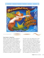
Trina Wai
Trina Wai created her playful panda by taking
full advantage of Illustrator CS's 3D Revolve
and 3D Extrude and Bevel effects. She started
with a series of very simple flat shapes and
ended with a truly organic look. Wai began by
drawing an open path for one side of the pan-
da's head. Choosing Effect>3D >Revolve, she
rotated the path 360° along its left edge. To
create the soft shiny reflections of the panda's
fur, Wai specified plastic shading as the surface
type and added additional light sources using
the New Light button. The bamboo stalk was
also revolved from a simple open path, then
rotated and grouped with a set of flat leaf
shapes. Wai then extruded the main body parts
by selecting 3D Extrude and Bevel. Each shape
received its own extrusion depth ranging from
150 pt for the legs and body, 37.5 pt for the
ears, 30 pt for the nose and 7 pt for the areas
surrounding the eyes. Each shape also received
a rounded bevel and plastic shading lit with a
single light source. The small eyes were created
using a blend between a large black circle and
a smaller gray circle.
322 Chapter 9 Live Effects & Graphic Styles
Mordy Golding / Adobe Systems, Inc.
To demonstrate the 3D effect of Illustrator CS,
Adobe Product Manager Mordy Golding cre-
ated a wine label and then dragged the label
to the Symbols palette (so he could use it next
to create the 3D rendering). He drew a half-
bottle shape and selected Effect >3D >Revolve.
In the 3D Revolve Options dialog box, Golding
clicked the Preview checkbox and then clicked
on the Map Art button. From the Map Art dia-
log box's Symbol menu, he selected the wine
label symbol he had created previously. Back
in the 3D Revolve Options dialog box, Golding
adjusted the preview cube, changing the rota-
tion angles until he was satisfied with the look
of the bottle. He finished the effect by adding
lights, using the New Light icon in the Surface
panel of the dialog box; this created the cas-
cading highlights on the bottle. After creating
the cork, using the same technique as he used
for the bottle, Golding selected the bottle,
moved it above the cork, and changed its opac-
ity to 94% in the Transparency palette.
Chapter 9 Live Effects & Graphic Styles
323
Tom Patterson / National Park Service
Cartographer Tom Patterson used Illustrator's
3D effect to show species movement across the
Sonoran Desert. Patterson drew a straight path
with the Pen tool and chose a 20 pt stroke. To
turn the path into an arrow, he chose Effect >
Stylize >Add Arrowheads. In the Add Arrow-
heads dialog box, he selected an arrowhead
design (11) and specified 25% for Scale. Next,
Patterson chose Effect >3D > Rotate and in the
3D Rotate Options dialog box, he enabled the
Preview and dragged the three-dimensional
cube in the Position pane to adjust the spatial
orientation of the arrow. When the arrow
looked right, he clicked OK. To fill the arrow,
Patterson first chose Object >Group to change
the arrow from an object to a group. Then he
selected Add New Fill from the Appearance
palette menu and applied a custom gradient
to the new fill. He repeated these steps to cre-
ate the other three arrows. To finish, Patterson
targeted the layer containing the arrows and
changed opacity to 80% in the Transparency
palette; he also added a drop shadow (Effect >
Stylize >Drop Shadow) to the layer.
324 Chapter 9 Live Effects & Graphic Styles
Joe Lertola/TIME
Joe Lertola of TIME Magazine relied on the 3D
Effect (Effect >3D > Extrude & Bevel) to turn
an otherwise flat map into an eye-catching 3D
thematic map. After drawing all the artwork,
Lertola created groups for the gray states and
the colored states. To give each group a differ-
ent height, he applied the 3D Effect to each
group, but specified a different Extrude Depth
value in the 3D Extrude & Bevel Options dialog
box for each group (6 pt for the gray states and
24 pt for the colored states). Lertola completed
the effect by adding a second light (he clicked
on the New Light icon in the Surface panel)
to change the position of the highlight and
shadow of each group.
Chapter 9 Live Effects & Graphic Styles 325
Scribble Basics
Applying Scribble Effects to Artwork
Shown here in Outline mode, Stead created her
first tree by drawing with the brush tool
After switching the color scheme for her second
tree, Stead selected the red rectangle back-
ground, hid the edges, and applied the Custom
Scribble option from the Effects menu
Judy Stead's evergreen tree began simply, but with the
help of Illustrator's brand new Scribble effect, it evolved
into an eye-catching Christmas card. Here, you will learn
how to apply the Scribble effect to your artwork, how to
make use of the preset Scribble styles, and how to make
custom adjustments to the effect in order to add excite-
ment and energy to your art.
1 Creating the base art and the variations. Stead began
by using the Brush tool to create a simple, filled shape for
the tree. She used a 5 pt round Calligraphic brush to cre-
ate the star, and applied a red stroke and a yellow fill to
the path. The ornament was drawn using the same brush
and stroke with a magenta fill added. Stead copied and
pasted this shape several times to decorate her tree. She
created the base of the tree using a 12 pt oval Calligraphic
326 Chapter 9 Live Effects & Graphic Styles
Overview: Applying default Scribble
effect settings; choosing from pre-
set Scribble styles; making custom
adjustments to Scribble settings.
brush to draw a single horizontal stroke. She then made
three copies and grouped them against a white rectangle.
Stead decided that her card would contain three
variations of the first tree, so she copied and pasted them
into position and gave each one a different color scheme.
Beginning with the first variation, she selected the red
background rectangle. She chose Effects > Stylize > Scrib-
ble, after first hiding the selection edges of her art ( -Y)
in order to observe the results more clearly. When the
Scribble Options menu appeared, Stead clicked Preview.
Satisfied with the Default settings, she clicked OK. These
settings applied the appearance of a loose, continuous
stroke to her solid red rectangle.
2 Using the Scribble presets. For her next variation,
Stead first selected the light green tree and chose the
Scribble style set entitled Sketch. She decided to leave
the Sketch settings as they were and clicked OK. Then
she selected the magenta background. After applying the
Scribble style set entitled Sharp, she opened up the dense-
ness of the effect's strokes by using the slider to change
the Spacing value from 3 pt to 5 pt. The Scribble Options
palette also contains sliders to control the thickness of
the stroke, the general curviness of the strokes, and the
degree of variation or evenness of the effect.
3 Further Scribble settings. For the final variation, Stead
selected the green background and chose the Swash set-
tings from the Options palette. Using the circular Angle
slider, she changed the preset angle of the strokes from 0
to -30 degrees. Stead then selected all the ornaments on
the tree and applied a final Scribble effect using the Dense
settings from the Scribble Options palette. Stead was able
to go back and readjust all her settings, as needed, by
clicking the instance of the effect in each object's Appear-
ance palette. As a final touch, Stead selected the solid red
tree and sent it backward (Object > Arrange > Send Back-
ward) so that the green Swash scribble effect would over-
lay the tree and provide an interesting texture.
For the light green Christmas tree, Stead chose
the Sketch from the Scribble palette's Settings
Stead applied the Scribble palette's Sharp set-
tings to the background, changing spacing set-
ting from 3 pt to 5 pt for a looser appearance
Stead applied Swash from the Scribble palette's
Settings to the green background of the final
tree art, and changed the angle of the strokes
using the Angle slider in the Options palette
(which then changed the "Settings" to Custom)
Hiding edges to see the effect
Applying a Scribble effect can
generate a complex set of edges
that make it difficult to view the
artwork underneath. Get into the
habit of hiding the edges of your
selection before trying out an ef-
fect. Use the -Y keyboard short-
cut to toggle the visibility of the
edges on and off.
Chapter 9 Live Effects & Graphic Styles
327
Todd Macadangdang/Adobe Systems, Inc.
Todd Macadangdang used the Scribble effect
to turn this photo into an artistic Crosshatch
sketch. Todd started by adjusting the colors
and posterizing the photograph in Photoshop,
using adjustment layers. He then placed the
image in Illustrator and created filled shapes
based on the posterized areas. Starting with
the smallest, front-most area, he clicked on
the area with the Eyedropper tool to set the
Fill color (with Stroke set to None), then traced
over it using the Pencil tool. He repeated this
process, working his way toward the largest
back-most areas; using Object >Arrange >Send
Backward as he went along to keep the shapes
in the correct visual stacking order. Todd then
applied the Scribble effect to each traced area.
To give his image a greater sense of depth, he
created fatter, looser Scribble strokes (using
Settings such as Childlike, Loose, or Snarl) for
the front-most areas and used smaller denser
strokes (with the Angle setting rotated 90°) for
the larger back-most crosshatched areas.
328
Chapter 9 Live Effects & Graphic Styles