Real World Adobe InDesign CS4- P12 potx
Bạn đang xem bản rút gọn của tài liệu. Xem và tải ngay bản đầy đủ của tài liệu tại đây (864.86 KB, 30 trang )
-
Creating Style Groups
To make a new style group with
already-created styles, select the
styles you want to include and
choose New Group from Styles.
InDesign displays
the New Style Group
dialog box. Enter a
name for the group.
InDesign moves the styles
into the style group.
You can duplicate styles
from one group to another
by holding down Option/Alt
as you drag them from in
the panel.
Quick Apply shows you both
style name and style group.
know which of your styles you want in your group, you can add them
while creating the group by rst selecting them rst (see Figure 4-70).
Once you’ve created a style group, you can move any style into
it by dragging the style name in the panel into the group. It’s very
similar to working with folders in your operating system.
One of the coolest things about style groups is that you can have
the same-named styles in more than one group. For example, you
might make a “bodytext” paragraph style in a group called “Business
Section” and another, dierently-styled “bodytext” style in a group
called “Entertainment Section”. We’re not saying you have to create
templates like this, but it can be useful in certain situations.
To copy one or more selected styles to another group, choose
Copy to Group from the panel menu, or Option/Alt-drag them over
another folder.
What’s Wrong with Style Groups? At rst, style groups sound great,
especially if you have dozens of styles in your document. But you
need to be careful with them. First, if do have same-named styles
Real_World_Adobe_InDesign_CS4b.pdf 331Real_World_Adobe_InDesign_CS4b.pdf 331 08/04/2009 05:55:00 p.m.08/04/2009 05:55:00 p.m.
.
with dierent denitions, it can be confusing which bodytext or
which heading you’re applying. is calls for eternal vigilance. It
helps if you apply styles with Quick Apply, because the Quick Apply
window displays both the style name and what style group its in.
e big problems appear if you need to export your documents as
RTF (rich text format) for someone who is editing in Microso Word.
Style groups will cause huge headaches because on export InDesign
changes the style names (it adds the style group name). is isn’t
so bad except that when you reimport the RTF le, it’s not smart
enough to remap the style names back to the document’s styles, so
you end up with all your styles duplicated. It’s horrible. We hope that
Adobe will release a patch to x this problem by the time you read
this, but we’re not holding our breath. Of course, in the meantime,
it’s a good excuse to get your editors to use InCopy instead.
Copying Styles from Other Publications
One of the great things about character and paragraph styles is that
you can use them to unify standard formatting across a range of pub-
lications—the chapters of this book, for example. While you can’t
dene a “master” style sheet and have all publications get their style
denitions from it (as you can in FrameMaker), you can easily copy
styles from one InDesign publication to another.
To copy character styles from another publication, choose
Load Character Styles from the Character Styles panel menu.
InDesign displays the Open a File dialog box. Locate and select
the InDesign publication le containing the styles you want and
click the Open button. InDesign copies the character styles from
that publication into the current document.
To copy paragraph styles from one publication to another
choose Load Paragraph Styles from the Paragraph Styles panel
menu.
To import both character and paragraph styles from another
publication, choose Load All Text Styles from the panel menu
of the Character Styles panel or the Paragraph Styles panel.
When you import styles that have the same name as styles that
already exist in the publication, InDesign overrides the attributes of
the existing styles with the attributes of the incoming styles.
You can also move styles by copying text tagged with the styles
you want from one publication and pasting it into another document
Real_World_Adobe_InDesign_CS4b.pdf 332Real_World_Adobe_InDesign_CS4b.pdf 332 08/04/2009 05:55:01 p.m.08/04/2009 05:55:01 p.m.
(or dragging a text frame from one document into another). If
the styles do not exist in the document you’ve pasted the text into,
InDesign adds them. If the styles already exist, InDesign overrides
the style denitions in the incoming text with the style denitions of
the existing styles.
You can also synchronize style sheets among all the documents in
a book when you use the Book panel, which we talk about in Chapter
8, “Long Documents.”
Styles from imported text les. When you import a Microso Word
or RTF le that includes paragraph or character styles that don’t exist
in the InDesign publication, those styles get added to the Character
Styles and Paragraph Styles panels. You can always tell one of these
styles from those created in InDesign because the panels display a
little gray oppy disk icon next to the style name.
Libraries of Styles. One of our favorite uses for libraries (see “Library
panel” in Chapter 1, “Workspace”) is to save paragraph and charac-
ter styles that we use in multiple documents. In a small text frame,
we type a few words (usually the name of the style) and then apply
one or more styles to them. en we drag the text frame into a library
(select Library from the New submenu, under the File menu, if you
haven’t already made one) and double-click on the library thumbnail
to give it a name and description. Later, when we need that style in
some other document, we can open the library le, drag that text
frame into our document, and then delete the text frame—the styles
remain. Of course, this works with libraries of color swatches, too.
Optical Margin Alignment
Ever since Gutenberg set out to print his Bible, typesetters have
looked for ways to “balance” the edges of columns of text—particu-
larly lines ending or beginning with punctuation. Because the eye
doesn’t “see” punctuation, it can sometimes appear that the le or
right edges of some columns of type (especially justied type) are
misaligned. Some other programs compensate for this problem
by using a “hanging punctuation” feature, which pushes certain
punctuation characters outside the text column. But there’s more
to making the edges of a column look even than just punctuation.
Some characters can create a “ragged” look all by themselves—think
of a “W,” at the beginning of a line, for example.
Real_World_Adobe_InDesign_CS4b.pdf 333Real_World_Adobe_InDesign_CS4b.pdf 333 08/04/2009 05:55:01 p.m.08/04/2009 05:55:01 p.m.
.
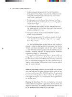
When you select an InDesign story (with either the Selection or
the Type tool) and turn on the Optical Margin Alignment option
in the Story panel (choose Story from the Type menu to display the
Story panel), the program balances the edges of the columns based
on the appearance of all of the characters at the beginning or end of
the lines in the column. is adjustment makes the columns appear
more even—even though it sometimes means that characters are
extending beyond the edges of the column (see Figure 4-71).
e amount that InDesign “hangs” a character outside the text
column depends on the setting you enter in the Base Size eld of
the Story panel (that’s the eld with the icon that looks like it would
make a drop cap). In general, you should enter the point size of your
body text in this eld.
Unfortunately, it turns out that many designers don’t like the look
of Optical Margin Alignment. It’s not that the feature is awed; it’s
that designers (especially younger folks) have become so accustomed
to their type lining up with a particular guide or ruler that they
think it’s wrong to have type inside or outside that (non-printing)
line. Nevertheless, we encourage you to try turning it on and seeing
how your readers like it—we think they’ll nd the text easier to read.
Ignore Optical Margin. Even if you do like Optical Margin Align-
ment, there’s a good chance that you’ll occasionally nd a paragraph
Optical Margin Alignment o
Optical Margin Alignment on
In this close-up view, you can clearly
see the way that InDesign adjusts
the characters at the edge of the text
column.
Punctuation is
positioned outside
the column.
Some characters
hang outside the
column
others are
moved farther
inside the column.
-
Optical Margin
Alignment
Real_World_Adobe_InDesign_CS4b.pdf 334Real_World_Adobe_InDesign_CS4b.pdf 334 08/04/2009 05:55:01 p.m.08/04/2009 05:55:01 p.m.
or two that you wish it wouldn’t apply to. For example, monospaced
code listings should not be optically aligned—that defeats the pur-
pose of using a monospaced font. Fortunately, you have the option
to turn o Optical Margin Alignment on a paragraph by paragraph
basis or in a paragraph style.
To turn it o for one or more selected paragraphs, choose Ignore
Optical Margin from the Control panel or Paragraph panel menu.
To disable it in a paragraph style, turn on the Ignore Optical Margin
checkbox in the Indents and Spacing pane of the Paragraph Style
Options dialog box.
An Old Typesetter Never…
Late night. e sound of the espresso machine in the kitchen about
to reach critical mass and melt down, destroying the oce and civi-
lization as we know it. e oce is dierent, the equipment and the
coee are better, but we still seem to be up late at night setting type.
And, to tell you the truth, we’re not sure we would have it any
other way.
Real_World_Adobe_InDesign_CS4b.pdf 335Real_World_Adobe_InDesign_CS4b.pdf 335 08/04/2009 05:55:01 p.m.08/04/2009 05:55:01 p.m.
You can use InDesign’s drawing tools to draw almost anything—
from straight lines and boxes to incredibly complex freeform shapes.
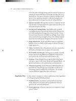
e drawing tools can be divided into three types: the Rectan-
gle, Polygon, Oval, and Line tools are for drawing basic shapes; the
Pencil, Smooth, Eraser, Pen, Add Point, Delete Point, and Convert
Point tools draw or edit more complex paths (see Figure 5-1). e
Scissors tool gives you a way of cutting paths.
Some of the path drawing tools (the Rectangle, Oval, and Polygon
tools) have counterparts that draw frames (the Rectangular Frame,
Oval Frame, and Polygonal Frame tools). e only thing dierent
about these tools is that the “frame” versions draw paths whose con-
tent type has been set to “Graphic.” at’s it.
In this book, we’ll use the default variant of the tool to refer to
both tools—when we say “the Rectangle tool,” we’re referring to both
the Rectangle tool and the Rectangular Frame tool.
Which path drawing tools should you use? Don’t worry too much
about it—the basic shapes can be converted into freeform paths, and
the freeform drawing tools can be used to draw basic shapes.
e paths you draw in InDesign are made up of points, and the
points are joined to each other by line segments (see Figure 5-2).
A path is just like a connect-the-dots puzzle. Connect all the dots
together in the right order, and you’ve made a picture. Because points
along a path have an order, or winding, you can think of each point
as a milepost along the path. Or as a sign saying, “Now go this way.”
Drawing
5
Real_World_Adobe_InDesign_CS4b.pdf 336Real_World_Adobe_InDesign_CS4b.pdf 336 08/04/2009 05:55:01 p.m.08/04/2009 05:55:01 p.m.
Freeform path drawing tools
Pen tool
Pencil tool
Path editing tools
Add Point tool
Delete Point tool
Convert Point tool
Scissors tool
Smooth tool
Erase tool
Basic shape tools
Rectangle tool
Ellipse tool
Polygon tool
Rectangle Frame tool
Ellipse Frame tool
Polygon Frame tool
Line tool
First point in the path
Last point in the path
Point
Line segment
Control handle
Control handle
Line segment
-
Parts of a Path
-
Drawing Tools
Drawing Basic Shapes
e basic shapes tools (the Rectangle, Polygon, Ellipse, and Line
tools, and their frame-drawing counterparts) don’t draw anything
you couldn’t draw using the Pen tool (discussed later in this chapter)
or (even) the Pencil tool; they just make drawing certain types of
paths easier. ey’re shortcuts.
e operation of the basic shapes tools is straightforward: drag
the tool and get a path of the corresponding shape. If you want to
draw a frame, you can either use the frame-drawing variant of the
tool, or draw the path and then convert it to a frame.
To draw a rectangle, oval, polygon, or line, follow the steps below.
1. Select the appropriate tool from the Tools panel.
To specify the type of polygon you’ll be drawing, double-click
the Polygon tool and choose the shape you want in the Polygon
Settings dialog box before you start drawing.
2. Position the cursor where you want one corner of the shape,
then drag. InDesign draws a path, starting where you rst held
down the mouse button.
Real_World_Adobe_InDesign_CS4b.pdf 337Real_World_Adobe_InDesign_CS4b.pdf 337 08/04/2009 05:55:01 p.m.08/04/2009 05:55:01 p.m.
.
To draw squares, hold down Shi as you drag the Rectangle
tool. To draw circles, hold down Shi as you drag the Ellipse
tool. When you hold down Shi as you drag, the Polygon tool
produces equilateral polygons. Holding down Shi as you drag
the Line tool constrains the angle of the line to 45-degree tan-
gents from the point at which you started dragging.
Hold down Option to draw a basic shape from its center.
3. When the basic shape is the size and shape you want it to be,
stop dragging and release the mouse button.
You can also create rectangles and ellipses by specifying their width
and height (see Figure 5-3).
1. Select the Rectangle tool or the Ellipse tool from the Tools panel.
2. Position the cursor where you want to place one corner of the
basic shape, or hold down Option/Alt and position the cursor
where you want to place the center point of the shape.
3. Click. InDesign displays the Rectangle dialog box (if you’ve
selected the Rectangle tool) or the Ellipse dialog box (if you’ve
selected the Ellipse tool).
4. Enter values in the Width and Height elds, then click
the OK button.
You can control the origin of
the basic shape by selecting a
point on the Control panel’s
Proxy before you click.
Select a basic shape
tool, then click on the
page or pasteboard.
InDesign displays a dialog
box (Rectangle, Polygon,
or Ellipse). Enter the
dimensions you want and
click the OK button.
InDesign creates a
basic shape using
the dimensions you
entered.
-
Adding a Basic Shape
“by the Numbers”
Points and Paths
Why is it that the most important things in life are oen the most dif-
cult to learn? Drawing by manipulating Bezier paths—the geomet-
ric construct used to represent path shapes in most of today’s vector
drawing programs—is one of those dicult things. When we rst
encounted Bezier curves, the process of drawing by placing points
and manipulating control handles struck us as alien, as nothing like
drawing at all. en we started to catch on.
Real_World_Adobe_InDesign_CS4b.pdf 338Real_World_Adobe_InDesign_CS4b.pdf 338 08/04/2009 05:55:01 p.m.08/04/2009 05:55:01 p.m.
In many ways, we had been drawing lines from the point of view
of everything but the line; in a Bezier-path-drawing program such as
InDesign, we draw lines from the point of view of the line itself. is
is neither better nor worse; it’s just dierent and takes time to get
used to. If you’ve just glanced at the Pen tool and are feeling confused,
we urge you to stick with it. Start thinking like a line.
Imagine that, through the action of some mysterious potion or
errant cosmic ray, you’ve been reduced in size so that you’re a little
smaller than one of the dots in a connect-the-dots puzzle. For added
detail and color, imagine that the puzzle appears in a Highlights for
Children magazine in a dentist’s oce.
e only way out is to complete the puzzle. As you walk, a line
extends behind you. As you reach each dot in the puzzle, a sign tells
you where you are in the puzzle and the route you must take to get to
the next dot in the path.
Get the idea? e dots in the puzzle are points. e route you walk
from one point to another, as instructed by the signs at each point, is
a line segment. Each series of connected dots is a path. As you walk
from one dot to another, you’re thinking like a line.
Each point—from the rst point in the path to the last—carries
with it some information about the line segments that attach it to the
previous and next points along the path.
Paths and their formatting (ll and stroke) attributes are dierent
things. Even if the ll and stroke applied to the path is “None” or the
stroke weight is 0 there’s still a path there.
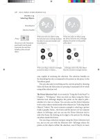
When you select a point, the point “lls in,” becoming a solid
square. Unselected points on the path are shown as hollow squares.
Paths have a direction, also known as “winding” (as in “winding a
clock”). Path direction generally corresponds to the order in which
you placed the points on the path (see Figure 5-4). In our connect-
the-dots puzzle, path direction tells us the order in which we should
connect the dots.
To reverse the direction of a path, select the path and choose
Reverse Path from the Paths submenu of the Object menu. InDesign
inking Like a Line
Winding
12 3 4 5
e order in which
you create points
determines the
direction (or “wind-
ing”) of the path.
-
Path Direction,
or “Winding”
Real_World_Adobe_InDesign_CS4b.pdf 339Real_World_Adobe_InDesign_CS4b.pdf 339 08/04/2009 05:55:02 p.m.08/04/2009 05:55:02 p.m.
.
reverses the direction of the path. You can also reverse the direction
of a selected path using the Reverse Path path operation, as discussed
in “Path Operations,” later in this chapter.
Points on an InDesign path are either corner points or curve points.
Each type of point has its own special properties.
A curve point adds a curved line segment between the current
point and the preceding and following points along the path.
Curve points have two control handles extended from them,
and moving one control handle aects the position of the other
control handle. One control handle aects the curve of the line
segment following the curve point on the path; the other aects
the curve of the line segment preceding the curve point. Curve
points are typically used to add smooth curves to a path (see
Figure 5-5).
A corner point adds a straight line segment between the cur-
rent point and the preceding point on the path (see Figure 5-6).
Corner points are typically used to create paths containing
straight line segments.
Which point type should you use? Any type of point can be
turned into any other type of point, and anything you can do with
one kind of point can be done with the other kind of point. Given
these two points (so to speak), you can use the kinds of points and
drawing tools you’re happiest with and achieve exactly the results
you want. ere is no “best way” to draw with InDesign’s Pen tool,
but it helps to understand how the method you choose works.
Point Types
Curve points curve the line segments
attached to the point. All of the points in
this example are curve points.
Corner points, by default, apply no curve
to the line segments attached to the point.
All of the points in this example are
corner points.
-
Corner Points
-
Curve Points
Real_World_Adobe_InDesign_CS4b.pdf 340Real_World_Adobe_InDesign_CS4b.pdf 340 08/04/2009 05:55:02 p.m.08/04/2009 05:55:02 p.m.
You control the curvature of the line segments before and aer each
point using the point’s control handles. Points can have up to two
control handles attached to them. By default, new corner points have
none and curve points have two. Note that each line segment has
up to two control handles dening its curve—the “outgoing” control
handle attached to the point dening the start of the line segment
and the “incoming” control handle attached to the next point.
If you retract the control handle (by dragging it inside the point),
the control handle has no eect on the curvature of the path. is
doesn’t necessarily mean that the line segment is a straight line,
however—a control handle on the point at the other end of the line
segment might also have an eect on the curve of the line segment.
e control handles attached to a corner point can be adjusted
independently, while changing the angle of one control handle of a
curve point changes the angle of the other control handle (see Figure
5-7). is dierence, in our opinion, makes corner points more
useful than curve points—you can do anything with a corner point
you could do with a curve point.
Control Handles
When you adjust one
control handle on a
curve point, InDesign
adjusts the other con-
trol handle, as well.
To adjust the curvature
of a line segment without
changing the curve of the
following line segment,
use a corner point.
-
Curve Points vs.
Corner Points
To convert a point from one point type to another, click the point
using the Convert Point tool. If you click a curve point, this retracts
both control handles. To convert a curve point to a corner point
while leaving one of its control handles in place, drag the other con-
trol handle using the Convert Point tool (see Figure 5-8).
Drawing Paths with the Pencil Tool
e quickest way to create a freeform path on an InDesign page is
to use the Pencil tool. Click the Pencil tool in the Tools panel (or
press N), then drag the Pencil tool on the page. As you drag, InDesign
creates a path that follows the cursor, automatically placing corner
and curve points as it does so (see Figure 5-9).
Real_World_Adobe_InDesign_CS4b.pdf 341Real_World_Adobe_InDesign_CS4b.pdf 341 08/04/2009 05:55:02 p.m.08/04/2009 05:55:02 p.m.
.
Position the Convert
Point tool over a
curve point…
…and click. InDesign
converts the curve
point to a corner point.
To convert a corner point
to a curve point, drag the
Convert Point tool over
the point.
To convert a curve
point to a corner point,
drag one of the control
handles using the
Convert Point tool.
InDesign converts the
curve point to a corner
point. As you drag the
control handle…
…InDesign adjusts the
curve of the correspond-
ing line segment, but
leaves the other line
segment unchanged.
-
Converting from One
Point Type to Another
Drag the Pencil tool on the
page or pasteboard.
As you drag the Pencil tool, InDesign
positions curve and corner points.
the path looks the way you want it
to, stop dragging.
-
Drawing with
the Pencil Tool
Drawing Paths with the Pen Tool
You use the Pen tool and its variants (the Remove Point, Add Point,
and Convert Point tools)—to create and edit paths.
When you click the Pen tool on a page, InDesign places a corner
point. Drag the Pen tool, and InDesign places a curve point where
you started dragging—you determine the length of the control han-
dles (and, therefore, the shape of the curve) by dragging as you place
the curve point (see Figure 5-10).
To curve the line segment following a corner point, place the
corner point, position the Pen tool above the point (this switches
to the Convert Point tool), and then drag. As you drag, InDesign
extends a control handle from the point (see Figure 5-11).
Real_World_Adobe_InDesign_CS4b.pdf 342Real_World_Adobe_InDesign_CS4b.pdf 342 08/04/2009 05:55:02 p.m.08/04/2009 05:55:02 p.m.
Position the Pen tool
above a point (it will
change into the Convert
Point tool).
Drag a control handle
out of the point.
Click the Pen tool to add
a point. InDesign curves
the line segment connect-
ing the points.
Drag the Pen tool… …and InDesign creates a curve point.
Click the Pen tool… …and InDesign creates a corner point.
-
Dragging a Control
Handle Out of
a Corner Point
-
Placing Curve
and Corner Points
e odd thing about using the Pen tool this way is that you don’t
see the eect of the curve manipulation until you’ve placed the next
point. is makes sense in that you don’t need a control handle for a
line segment that doesn’t yet exist, but it can be quite a brain-twister.
To convert a curve point you’ve just placed to a corner point, posi-
tion the Pen tool above the point (to switch to the Convert Point tool)
and then click the point. InDesign converts the point to a corner
point and retracts the point’s control handles.
You can change the position of points: select the point with the
Direct Selection tool, then drag the point to a new location.
Drawing Techniques
Now that you know all about the elements that make up paths, let’s
talk about how you actually use them.
When you’re drawing paths, don’t forget that you can change the
path aer you’ve drawn it. We’ve oen seen people delete entire
paths and start over because they misplaced the last point on the
Path Drawing Tips
Real_World_Adobe_InDesign_CS4b.pdf 343Real_World_Adobe_InDesign_CS4b.pdf 343 08/04/2009 05:55:02 p.m.08/04/2009 05:55:02 p.m.
.
path. Go ahead and place points in the wrong places; you can always
change the position of any point. Also, keep these facts in mind:
You can always add points to or subtract points from the path.
You can change tools while drawing a path.
You can split the path using the Scissors tool.
It’s also best to create paths using as few points as you can—but
it’s not required. We’ve noticed that people who have just started
working with Bezier drawing tools oen use more points than are
needed to create their paths. Over time, they learn one of the basic
rules of vector drawing: Any curve can be described by two points
and their associated control handles. No more, no less.
e aspect of drawing in InDesign that’s toughest to understand
and master is the care, feeding, and manipulation of control handles.
ese handles are fundamental to drawing curved lines, so you’d
better learn how to work with them.
To adjust the curve of a line segment, use the Direct Selection
tool to select a point attached to the line segment. e control han-
dles attached to that point—and to the points that come before and
aer the selected point on the path—appear. If you don’t see control
handles attached to the point you selected, the curvature of the line
segment is controlled by the points at the other end of the line seg-
ments. Position the cursor over one of the control handles and drag.
e curve of the line segment changes as you drag. When the curve
looks the way you want it to, stop dragging (see Figure 5-12).
To retract (delete) a control handle, drag the handle inside the
point it’s attached to.
You can also adjust the curve of a curved line segment by dragging
the segment itself. To do this, select the line segment (click the line
segment with the Direct Selection tool, or drag a selection rectangle
over part of the line segment) and then drag. As you drag, InDesign
adjusts the curve of the line segment (see Figure 5-13).
Manipulating
Control Handles
Select a point
using the Direct
Selection tool.
Drag the control handle attached to
the point to a new location.
InDesign curves
the line segment.
-
Adjusting Curve Points
Real_World_Adobe_InDesign_CS4b.pdf 344Real_World_Adobe_InDesign_CS4b.pdf 344 08/04/2009 05:55:02 p.m.08/04/2009 05:55:02 p.m.
To add a point to an existing line segment, select the path, switch
to the Pen tool, and then click the Pen tool on the line segment.
InDesign adds a point to the path. You don’t need to select the Add
Point tool—InDesign will switch to it when you move the Pen tool
above a line segment.
To remove a point from a path, select the path, switch to the Pen tool,
and then click the Pen tool on the point. InDesign removes the point
from the path.
If you’ve gotten this far, you probably know how to select points, but
here are a few rules to keep in mind.
To select a point, click it with the Direct Selection tool, or drag a
selection rectangle around it (using the same tool).
You can select more than one point at a time. To do this, hold
down Shi as you click the Direct Selection tool on each point,
or use the Direct Selection tool to drag a selection rectangle
around the points you want to select.
To select all of the points on a path, hold down Option/Alt as
you click the Direct Selection tool on the path.
You can select points on paths inside groups or compound paths
by using the Direct Selection tool.
When you move a point, the control handles associated with
that point also move, maintaining their positions relative to the
point. is means that the curves of the line segments attached
to the point change, unless you’re also moving the points on the
other end of the incoming and outgoing line segments.
To move a straight line segment and its associated points, select
the line segment with the Direct Selection tool and drag.
Adding Points
to a Path
Removing Points
from a Path
Selecting and
Moving Points
Select a line segment using the Direct
Selection tool (drag a selection rect-
angle over the line segment).
Drag the line segment. As you
drag, InDesign adjusts the
curve of the line segment.
-
Another Way to
Adjust the Curve of
a Line Segment
Real_World_Adobe_InDesign_CS4b.pdf 345Real_World_Adobe_InDesign_CS4b.pdf 345 08/04/2009 05:55:03 p.m.08/04/2009 05:55:03 p.m.
.
Paths can be open or closed (see Figure 5-14). An open path has no
line segment between the beginning and ending points on the path.
You don’t have to close a path to add contents (text or a graphic) or
apply a ll to the path.
To close an open path, select the path, select the Pen tool, and
then click the Pen tool on the rst or last point on the path (it doesn’t
matter which). Click the Pen tool again on the other end point.
InDesign closes the path (see Figure 5-15).
Another way to close an open path is to use the Close Path path
operation, as discussed in “Path Operations,” later in this chapter.
To open a closed path, select the Direct Selection tool and click
the line segment between two points on the path (you can also
drag a selection rectangle over the line segment). Press Delete, and
InDesign removes the line segment, opening the path between the
points on either side of the line segment (see Figure 5-16).
To open a path without removing a line segment, select the Scis-
sors tool and click the path. Click on a point to split the path at that
point, or click a line segment to split the path at that location (see
Figure 5-17).
e point closest to the start of the path (following the path’s
winding) becomes the point farther to the back, and the point far-
thest from the start of the path is on top of it.
Another way to open a closed path is to use the Close Path path
operation, as discussed in “Path Operations,” later in this chapter.
Opening and
Closing Paths
Closed path. Open path. A path does not have to
be closed to have a ll.
Move the Pen tool over
an end point of an open
path.
Click the Pen tool, then
move it over the other
end point on the path.
Click on the end point.
InDesign closes the path.
-
Closing an Open Path
-
Open and Closed Paths
Real_World_Adobe_InDesign_CS4b.pdf 346Real_World_Adobe_InDesign_CS4b.pdf 346 08/04/2009 05:55:03 p.m.08/04/2009 05:55:03 p.m.
To join two open paths, follow these steps (see Figure 5-18).
1. Position the Pen tool above the start or end point of one of the
open paths (you don’t need to select a path). InDesign changes
the cursor to show that it’s ready to add a point to the path.
2. Click the Pen tool, then position the cursor over the start or end
point of the second path. InDesign changes the cursor to show
that it’s ready to connect the current path to the point.
3. Click the Pen tool. InDesign joins the two paths.
4. Repeat this process for the other two end points to close the path.
Alternatively, you can select two paths and choose Join from the
Paths submenu of the Object menu. InDesign will join the nearest
points of the two paths (with straight line segments).
Joining Open Paths
Select the Direct Selection tool, then drag a
selection rectangle over a line segment.
Press the Delete key to
delete the line segment.
Click a line segment or
point with the Scissors
tool.
InDesign opens the path. You can drag the path’s
end points apart, if necessary.
-
Opening a Closed Path
-
Opening a Closed Path
by Deleting a
Line Segment
Click the Pen tool on the
end point of one open
path, then click an end
point on the other path.
To close the path, click
one of the remaining
end points.
Click the other end point
to close the path.
-
Joining Two Open Paths
Real_World_Adobe_InDesign_CS4b.pdf 347Real_World_Adobe_InDesign_CS4b.pdf 347 08/04/2009 05:55:03 p.m.08/04/2009 05:55:03 p.m.
.
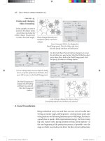
Compound Paths
In the old days, not only did Ole have to walk miles to school in
freezing cold weather, but he also had to work his way through an
impossibly dicult series of steps to create holes inside closed paths.
is did nothing to improve his already gloomy outlook on life.
ese days, creating holes in paths is easier—just make them
into compound paths. Compound paths are made of two or more
paths (which must be unlocked, ungrouped, and closed) that have
been joined using the Make Compound Paths option on the Paths
submenu of the Object menu. Areas between the two paths, or areas
where the paths overlap, are transparent. e following steps show
you how to make a torus, or “doughnut” shape (see Figure 5-19).
1. Select the Ellipse tool from the Tools panel.
2. Draw two ovals, one on top of the other.
3. Fill the ovals with a basic ll.
4. Select both ovals.
5. Press Command-8/Ctrl-8 to join the two ovals.
If you decide you don’t want the paths to be compound paths, you
can change them back into individual paths. To do this, select the
compound path and then choose Release Compound Path from the
Paths submenu of the Object menu.
Select the paths you
want to turn into a
compound path.
Choose Make Compound
Path from the Paths sub-
menu of the Object menu.
InDesign creates a
compound path from
the selected objects
(is makes a hole where
the shapes overlap).
is example shows
a compound path
that we’ve used as a
container for an image.
-
Creating a
Compound Path
Real_World_Adobe_InDesign_CS4b.pdf 348Real_World_Adobe_InDesign_CS4b.pdf 348 08/04/2009 05:55:03 p.m.08/04/2009 05:55:03 p.m.
When you join paths with dierent lines and lls, the compound
path takes on the stroke and ll attributes of the path that’s the far-
thest to the back.
You can subselect the individual points that make up a compound
path in the same way that you subselect objects inside a group—
select the Direct Selection tool and click on the point. Once a point is
selected, you can alter its position (see Figure 5-20).
Editing
Compound
Paths
Use the Direct Selection
tool to select some
points.
Transform (move, scale, shear, or rotate) the
points. In this example, we’ve dragged the
points to a new location.
-
Editing a
Compound Path
To convert a compound path back into two or more normal paths,
select the compound path and choose Release Compound Path
from the Paths submenu of the Object menu (or press Command-
Option-8/Ctrl-Alt-8). InDesign converts the compound path into its
component paths. Note that the paths do not return to their original
formatting when you do this.
If you’re familiar with Illustrator or other drawing programs, you’re
probably used to having two options for lling paths. ese options
go by dierent names in dierent applications, but they’re usually
known as the “Even Odd Fill Rule” and the “Zero Winding Fill Rule.”
ese rules control the way the application lls a path that intersects
itself, or the way the interior areas of a compound path are lled.
If you’ve pasted paths from these applications into InDesign, or
if you’ve drawn a self-intersecting path in InDesign, you’ve probably
discovered that InDesign supports the Zero Winding Fill Rule, but
not the Even Odd Fill Rule.
What the heck are we talking about? It’s much easier to show than
it is to describe (see Figure 5-21).
What can you do when you want the even/odd ll? Do you have
to leave InDesign, create the path in a drawing program, and then
import the path as a graphic?
is question drove Ole to the brink of madness before he dis-
covered that you can simulate the eect of the Even Odd Fill Rule
Splitting
Compound
Paths
Compound Paths and
Even-Odd Fill
Real_World_Adobe_InDesign_CS4b.pdf 349Real_World_Adobe_InDesign_CS4b.pdf 349 08/04/2009 05:55:03 p.m.08/04/2009 05:55:03 p.m.
.
using compound paths and the Add path operation (we’ll discuss
path operations later in this chapter). See Figure 5-22.
1. Select the self-intersecting path.
2. Copy the path, then use Paste In Place (Command-Option-Shi-
V/Ctrl-Alt-Shi-V) to create a duplicate of the object exactly on
top of the original object.
3. Select both items and click the Add button on the Pathnder
panel (Intersect will also work). InDesign creates a compound
path and lls it exactly as the original path would look if it had
been lled using the Even Odd Fill Rule.
-
Fill Rules
Self-intersecting path lled
using the Zero Winding Fill
Rule (InDesign).
Self-intersecting path lled
using the Even Odd Fill Rule
(Illustrator).
-
Simulating the Eect of
the Even Odd Fill Rule
Select the path, then copy
the path and paste the copy
on top of the original using
Paste In Place.
Click the Add button in the
PathFinder panel.
InDesign creates a composite
path that is lled using the
Even Odd Fill Rule.
Smoothing Paths
You like using the Pencil tool. But your mouse hand isn’t perfectly
steady. Or the jerk you share oce space with can’t resist the urge
to bump your arm while you’re drawing. Either way, you need a way
to smooth the path you’ve drawn in InDesign. Are you doomed to
an aer-hours workout with the Pen tool? Not with the Smooth tool
on your side. is handy gadget can help you smooth out the rough
patches in your InDesign paths.
Real_World_Adobe_InDesign_CS4b.pdf 350Real_World_Adobe_InDesign_CS4b.pdf 350 08/04/2009 05:55:04 p.m.08/04/2009 05:55:04 p.m.
To use the Smooth tool, select the tool from the Tools panel (it’s
usually hiding under the Pencil tool). Or select the Pencil tool and
hold down Option/Alt to change the Pencil tool to the Smooth tool.
Drag the tool along the path you want to smooth (see Figure 5-23).
As you drag, InDesign adjusts the control handles and point posi-
tions on the path (sometimes deleting points as you drag).
To control the operation of the Smooth tool, double-click the
Smooth tool in the Tools panel. InDesign displays the Smooth Tool
Preferences dialog box (see Figure 5-24). e Fidelity slider controls
the distance, in screen pixels, that the “smoothed” path can vary
from the path of the Smooth tool (higher values equal more adjust-
ment and greater variation from the existing path). e Smoothness
slider controls the amount of change applied to the path (higher
values equal greater smoothing).
Select the Smooth tool
from the Tools panel.
Select a path.
Drag the Smooth
tool over the path.
InDesign smooths the path by adjusting
control handles, moving points on the path,
and deleting points.
-
Smooth Tool Prefer-
ences
-
Smoothing a Path
Erasing Paths
Imagine that you want to remove an arbitrary section of a path, and
that the beginning and end of the section do not correspond to exist-
ing points on the path. To do this, select the Erase tool from the Tools
panel, then drag the tool over the area of the path you want to delete
(see Figure 5-25).
Real_World_Adobe_InDesign_CS4b.pdf 351Real_World_Adobe_InDesign_CS4b.pdf 351 08/04/2009 05:55:04 p.m.08/04/2009 05:55:04 p.m.
.
Select the Erase tool from
the Tools panel, then select
a path.
Drag the Erase tool over the
parts of the path you want
to erase.
When you drag the Erase tool over a
line segment on a closed path, InDesign
opens the path. When you drag over an
open path, it gets split into two paths.
-
Erasing Part of a Path
Path Operations
Path operations—which is what we call the commands represented
by buttons on the Pathnder panel—create paths from other paths,
or change the shape of paths in some predened way. e rst row
of buttons in the Pathnder panel make it easy to create complex
shapes by combining simple geometric shapes, and to create shapes
that would be very dicult to draw using the Pen tool.
e Convert Shape operations provide a number of “utility” func-
tions for working with paths. Why did they end up in the same panel
with the Pathnder path operations they have little or nothing in
common with? ink carefully before you answer. Do you really
want another panel?
e Pathnder path operations work with the area(s) of intersec-
tion between two or more objects. ese path operations can merge
objects, or create new objects, or remove the area of one object from
another object.
Many people have gotten the impression that the path operations
are “advanced” drawing techniques. “I can’t draw,” they say, “so I
have no use for them. It’s hard enough just using the Pen tool.”
Nothing could be farther from the truth—if you can draw, the
path operations are a nice addition to your toolbox, but if you can’t
draw, or can’t draw with the Pen tool, InDesign’s path operations
can quickly become your best friend. ink about it—even David
can draw just about anything using rectangles, ellipses, and the
occasional polygon. By using path operations, you can do the same,
without ending up with stacks of overlapping shapes on your pages.
Real_World_Adobe_InDesign_CS4b.pdf 352Real_World_Adobe_InDesign_CS4b.pdf 352 08/04/2009 05:55:04 p.m.08/04/2009 05:55:04 p.m.
To apply any of the Pathnder path operations, select two or more
paths, display the Pathnder panel, and click the button correspond-
ing to the path operation you want to apply (see Figure 5-26).
We’ll cover what each of the path operations does, but rst, a few
ground rules:
Original shapes are deleted. Path operations oen consume
the selected shapes and create a new shape. is shape is oen
a compound path. To retain the original shapes, you’ll need to
duplicate them before applying the path eect.
Stacking order matters. Most of the path operations aect either
the foreground or background object in some predened way.
If you try a path operation and don’t get the result you expect,
undo, then shue the order of the objects (using Bring to Front,
Send to Back, Bring Forward, and Send Backward from the
Arrange submenu of the Object menu) and try again.
Formatting changes. In general, the ll, stroke, and other
attributes of the foreground object dene the formatting of the
resulting object. e exception is the Subtract path operation,
where the background object denes the formatting of the result.
Path operations and text frames. When you apply a path opera-
tion to a text frame, the shape of the frame is aected—not the
text in the frame.
Alternatives to clipping paths. You can sometimes use path
operations to avoid clipping paths and nested objects, which
can result in faster printing.
Watch out for path contents. Performing path operations
on objects that contain other objects—such as imported
graphics—sometimes deletes the path content.
e Add path operation creates a new path that has the outline of the
selected objects, removing the area of intersection and any interior
paths from the new object. If the original paths are composite paths,
any interior paths will be retained unless they intersect each other or
fall within the area of intersection of the shapes.
When you want to use one path to cut a hole in another, use the Sub-
tract path operation. It’s like a cookie cutter—the foreground object
cuts a hole in the background object. e resulting object takes on
the ll and stroke of the background object.
Applying Pathnder
Path Operations
Add
Subtract
Real_World_Adobe_InDesign_CS4b.pdf 353Real_World_Adobe_InDesign_CS4b.pdf 353 08/04/2009 05:55:04 p.m.08/04/2009 05:55:04 p.m.
.
e Intersect path operation creates a new object that is the shape of
the area of intersection of the objects in the selection. Intersect will
display an error message if the objects do not share a common area
of intersection.
As we’ve noted, path operations consume the selected objects.
ere are various ways to retain the original objects, but the quickest
by far is to apply the path eect, copy the resulting path, undo (which
restores the original paths), and then press Command-Option-Shi-
V/Ctrl-Alt-Shi-V to paste in place. is trick is particularly useful
when used with Intersect.
e Exclude Overlap path operation creates a compound path from
the selected objects, leaving any areas of intersection unlled.
e Minus Back path operation is the opposite of the Subtract path
operation. When you click the Minus Back button in the Pathnder
panel, InDesign uses the background object to cut a hole in the fore-
ground object. e resulting object takes on the formatting attri-
butes of the foreground object.
Intersect
Exclude Overlap
Minus Back
Select two or more objects…
-
Applying a
Path Operation
Click one of the buttons
in the Pathnder panel
(Add, in this example).
Subtract
Exclude Overlap
Intersect
Add
Minus Back
InDesign applies
the path operation
to the selected
objects.
We used lled shapes for the
two examples to the right
because it’s hard to see what
the path operations do with
unlled shapes.
e star is the
foreground object.
Real_World_Adobe_InDesign_CS4b.pdf 354Real_World_Adobe_InDesign_CS4b.pdf 354 08/04/2009 05:55:04 p.m.08/04/2009 05:55:04 p.m.
To apply any of the Convert Shape operations, select an object and
click one of the buttons in the Pathnder panel.
Convert to Rectangle. Converts the object to a rectangle.
Convert to Rounded-Corner Rectangle. Converts the object to
a rectangle and applies the Rounded corner option (using the
current corner radius setting).
Convert to Beveled-Corner Rectangle. Converts the object to a
rectangle and applies the Bevel corner option.
Convert to Inverse-Rounded-Corner Rectangle. Converts the
object to a rectangle and applies the Inverse Rounded corner
option (using the current corner radius setting).
Convert to Ellipse. Converts the object to an ellipse. If you have
a square selected, the resulting ellipse will be a circle.
Convert to Triangle. Converts the object to a triangle.
Convert to Polygon. Converts the object to a polygon, using the
current settings in the Polygon Settings dialog box. is means
that you can easily change one polygon into another.
Convert to Line. Converts the object to a line.
Convert to Vertical or Horizontal Line. Converts the object to a
vertical or horizontal line.
Open Path. Opens a closed path. Note that this operation does
not remove the last line segment in the path—it simply opens
the path at the rst/last point in the path.
Close Path. Closes an open path.
Reverse Path. Reverses the selected path.
Corner Options
Corner options can change that way corner points are drawn. Use
this feature to add rounded corners to rectangles and squares.
To apply a corner option to a page item, select the page item and
choose Corner Options from the Object menu. InDesign displays
the Corner Options dialog box. Choose the eect you want from the
Eect pop-up menu, enter a value in the Size eld, and then press
Return to apply your change. InDesign changes the corners of the
path based on the corner option you selected (see Figure 5-27).
Applying Convert
Shape Operations
Real_World_Adobe_InDesign_CS4b.pdf 355Real_World_Adobe_InDesign_CS4b.pdf 355 08/04/2009 05:55:05 p.m.08/04/2009 05:55:05 p.m.