Astm e 1040 10 (2016)
Bạn đang xem bản rút gọn của tài liệu. Xem và tải ngay bản đầy đủ của tài liệu tại đây (97.27 KB, 3 trang )
Designation: E1040 − 10 (Reapproved 2016)
Standard Specification for
Physical Characteristics of Nonconcentrator Terrestrial
Photovoltaic Reference Cells1
This standard is issued under the fixed designation E1040; the number immediately following the designation indicates the year of
original adoption or, in the case of revision, the year of last revision. A number in parentheses indicates the year of last reapproval. A
superscript epsilon (´) indicates an editorial change since the last revision or reapproval.
1. Scope
2. Referenced Documents
2.1 ASTM Standards:2
E772 Terminology of Solar Energy Conversion
E948 Test Method for Electrical Performance of Photovoltaic Cells Using Reference Cells Under Simulated Sunlight
E1036 Test Methods for Electrical Performance of Nonconcentrator Terrestrial Photovoltaic Modules and Arrays
Using Reference Cells
E1125 Test Method for Calibration of Primary NonConcentrator Terrestrial Photovoltaic Reference Cells Using a Tabular Spectrum
E1328 Terminology Relating to Photovoltaic Solar Energy
Conversion (Withdrawn 2012)3
E1362 Test Methods for Calibration of Non-Concentrator
Photovoltaic Non-Primary Reference Cells
2.2 Military Specification Sheet:4
MS3106C Connector, Plug, Electric, Straight, Solder
Contracts, AN Type
1.1 This specification describes the physical requirements
for primary and secondary terrestrial nonconcentrator photovoltaic reference cells. A reference cell is defined as a device
that meets the requirements of this specification and is calibrated in accordance with Test Method E1125 or Test Method
E1362.
1.2 Reference cells are used in the determination of the
electrical performance of photovoltaic devices, as stated in Test
Methods E948 and E1036.
1.3 Two reference cell physical specifications are described:
1.3.1 Small-Cell Package Design—A small, durable package with a low thermal mass, wide optical field-of-view, and
standardized dimensions intended for photovoltaic devices up
to 20 by 20 mm, and
1.3.2 Module-Package Design—A package intended to
simulate the optical and thermal properties of a photovoltaic
module design, but electric connections are made to only one
photovoltaic cell in order to eliminate problems with calibrating series and parallel connections of cells. Physical dimensions are not standardized.
3. Terminology
3.1 Definitions—For definitions of terms used in this
specification, see Terminologies E772 and E1328.
1.4 The values stated in SI units are to be regarded as
standard. No other units of measurement are included in this
standard.
4. Classification
4.1 Two types of reference cells are used in the evaluation
of the electrical performance of photovoltaic terrestrial devices:
4.1.1 Primary Reference Cells—Reference cells calibrated
directly in sunlight in accordance with Test Method E1125.
4.1.2 Secondary Reference Cells—Reference cells calibrated against a primary reference cell in accordance with Test
Method E1362.
1.5 This standard does not purport to address all of the
safety problems, if any, associated with its use. It is the
responsibility of the user of this standard to establish appropriate safety and health practices and determine the applicability of regulatory limitations prior to use.
2
For referenced ASTM standards, visit the ASTM website, www.astm.org, or
contact ASTM Customer Service at For Annual Book of ASTM
Standards volume information, refer to the standard’s Document Summary page on
the ASTM website.
3
The last approved version of this historical standard is referenced on
www.astm.org.
4
Available from Superintendent of Documents, U.S. Government Printing
Office, N. Capital and H Streets, NW, Washington, DC 20401.
1
This specification is under the jurisdiction of ASTM Committee E44 on Solar,
Geothermal and Other Alternative Energy Sources and is the direct responsibility of
Subcommittee E44.09 on Photovoltaic Electric Power Conversion.
Current edition approved July 1, 2016. Published August 2016. Originally
approved in 1984. Last previous edition approved in 2010 as E1040 – 10. DOI:
10.1520/E1040-16.
Copyright © ASTM International, 100 Barr Harbor Drive, PO Box C700, West Conshohocken, PA 19428-2959. United States
1
E1040 − 10 (2016)
are (1) an electrically and thermally conductive body with a
low thermal mass, (2) standardized mounting holes, (3) detachable cables using standardized female connectors on the side of
the package, (4) standardized temperature sensors, (5) a flat
rear surface without protrusions, (6) permanent identification
markings, and (7) standardized internal wiring.
5.2.2 Reference Cell Material—The WPVS design specifies
a monocrystalline float-zone Si solar cell because device
stability and quality are desirable for the primary reference
cells that constitute the WPVS. For other applications, additional considerations may be more important and therefore the
float-zone Si solar cell can be replaced with alternative device
types as required, such as polycrystalline Si or GaAs.
5.2.3 Window—The WPVS specifies a “durable, smooth
front window” to protect the photovoltaic cell. A colored glass
or other optical filter may also be used to modify the spectral
response of the cell, if necessary for specific applications.
5.2.3.1 Typical window materials are optical quality glass or
fused silica with a surface roughness of at most 40 nm/mm.
5.2.3.2 Because many colored glass filters have transmission characteristics that change with time, it may be necessary
to increase the frequency of recalibration of reference cells that
use colored glass filters.
5.2.4 Connectors—Subminiature connectors on one side of
the reference cell package avoid problems with integral cables
such as broken wires and flexing of thermocouple leads. The
connectors should be reliable and compatible with the package
size.
4.2 The two types are not physically or electrically different,
but are different in their manner of calibration. Hereafter in this
specification, both types of reference cells will be considered
alike and referred to only as reference cells.
5. Materials and Manufacture
5.1 Requirements for Both Reference Cell Designs:
5.1.1 Product Marking— A label, identification mark, or
serial number shall be permanently stamped or scribed on the
reference-cell holder. This product marking shall identify the
device for reference to other documentation containing electrical and mechanical data, including information such as the
cell material and manufacturer.
5.1.2 The reference cell shall be constructed using a single
photovoltaic cell. Note that in the case of the module-package
design, additional cells inside the package are allowed, but are
not connected electrically.
5.2 Small-Cell Package Design:
5.2.1 The small-cell package design is documented in the
literature as the World Photovoltaic Scale (WPVS) reference
cell package5; the WPVS design meets a number of goals that
are important for the small-cell package design. These goals
5
Osterwald, C. R., Anevsky, S., Bucher, K., Barua, A. K., Chaudhuri, P., Dubard,
J., Emery, K., Hansen, B., King, D., Metzdorf, J., Nagamine, F., Shimokawa, R.,
Wang, Y. X., Wittchen, T., Zaaiman, W., Zastrow, A., and Zhang, J., “The World
Photovoltaic Scale: An International Reference Cell Calibration Program, “Progress
in Photovoltaics: Research and Applications, Vol 7, July/August 1999, p. 287.
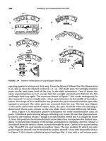
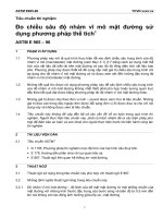
FIG. 1 Two Examples of Module-Package Reference Cell Configurations
2
E1040 − 10 (2016)
5.3.5 Electrical Connections—The electrical connections to
the photovoltaic cell shall consist of a four-wire contact system
(Kelvin probe), with two wires connected to the top contact of
the cell, and two wires to the bottom contact. A minimum
length of 1 m of 1.0 mm (AWG 18) diameter four-conductor
cable with an ultraviolet-stable outer cover rated for outdoor
usage is recommended.
5.3.6 Temperature Sensor—A temperature sensor shall be
attached in a way that will ensure good thermal contact with
the photovoltaic cell. To minimize heating during illumination,
the temperature sensor is normally located behind the photovoltaic cell. The temperature sensor cable should be able to
withstand flexing and connect-disconnect cycles to measurement equipment during use without breaking. Thermocouple
wire should not be allowed to bend or flex at locations where
temperature gradients are likely to occur.
5.3 Module-Package Design—Because the module-package
design is intended to simulate the thermal and optical properties of an actual module, the physical dimensions are not
standardized. Instead, materials and assembly techniques for
the reference cell are as similar as possible to the actual module
materials and assembly techniques. The electrical and optical
environments, as seen by the connected cell, are therefore
similar to actual modules. Two possible configurations of
module-package reference cells are shown in Fig. 1.
5.3.1 The upper configuration in Fig. 1 is a substrate solar
cell surrounded by pieces of unconnected solar cells laminated
in a typical module package.
5.3.2 The lower configuration in Fig. 1 simulates a monolithic superstrate design where individual cells are seriesconnected in a module, but for the reference cell one device in
the series string is isolated and connected to the reference cell
leads.
5.3.3 Because the size of module-package reference cells
can be much larger than the single-cell package, modulepackage reference cells are normally calibrated against a
primary reference cell. Therefore, module-package cells are
typically secondary reference cells.
5.3.4 Electrical Connector—The standard electrical connector shall be MS3106A14S-2S,6 as specified in Military Specification Sheet MS3106A. The leads from one side of the solar
cell shall be connected to contacts A and D on the connector,
and the leads from the opposite side shall be connected to
contacts B and C.
6. Documentation
6.1 A reference cell shall be accompanied by documentation
of its calibration constant, cell area, current-voltage
characteristic, temperature coefficient, and spectral response.
All material used in its construction shall be identified. The
photovoltaic cell used should be identified by the following
information, if available: manufacturer, production lot, production date, and relevant device design features, such as
resistivity, anti-reflectance coating, front surface preparation,
back surface preparation, or contact materials.
7. Keywords
6
Available from Amphenol Corp., 358 Hall Ave., Wallingford, CT 06492, as part
No. MS3106A14S-2S.
7.1 cell; package; photovoltaics, reference
ASTM International takes no position respecting the validity of any patent rights asserted in connection with any item mentioned
in this standard. Users of this standard are expressly advised that determination of the validity of any such patent rights, and the risk
of infringement of such rights, are entirely their own responsibility.
This standard is subject to revision at any time by the responsible technical committee and must be reviewed every five years and
if not revised, either reapproved or withdrawn. Your comments are invited either for revision of this standard or for additional standards
and should be addressed to ASTM International Headquarters. Your comments will receive careful consideration at a meeting of the
responsible technical committee, which you may attend. If you feel that your comments have not received a fair hearing you should
make your views known to the ASTM Committee on Standards, at the address shown below.
This standard is copyrighted by ASTM International, 100 Barr Harbor Drive, PO Box C700, West Conshohocken, PA 19428-2959,
United States. Individual reprints (single or multiple copies) of this standard may be obtained by contacting ASTM at the above
address or at 610-832-9585 (phone), 610-832-9555 (fax), or (e-mail); or through the ASTM website
(www.astm.org). Permission rights to photocopy the standard may also be secured from the Copyright Clearance Center, 222
Rosewood Drive, Danvers, MA 01923, Tel: (978) 646-2600; />
3