Robotics 2 E Part 10 ppt
Bạn đang xem bản rút gọn của tài liệu. Xem và tải ngay bản đầy đủ của tài liệu tại đây (728.62 KB, 30 trang )
260
Feeding
and
Orientation
Devices
FIGURE
7.34
Passive
orientation
of
cup-shaped
details.
opening upward continue
on
their way. From
the
figure
it
follows
that
the
dimensions
b,
d
lt
and
d
2
must
be
related
so
that
d
2
>b>d
l
.
The
guide puts
the
wrongly oriented
parts
on the
next lower level
of the
tray,
in the
right orientation.
Case
d)
shows
the
same separating idea
as in e),
except that
the
wrongly oriented parts
fall
into
the bin
and
begin their
way
again.
The
structure shown
in
Figure
7.34e)
works analogously.
In
this case part
1 is
more
complicated—it
has a
protuberance
in the
middle
of
the
inden-
tation.
The
shape
of
the
cutoff
in the
tray permits
the
parts oriented with
the
open side
upward
to
proceed.
The
other parts
are
removed
from
the
tray.
The
last case
(Figure
7.34f))
is for
parts
with small
h
values. Here,
the
part succeeds when
the
opening
is
downward. These parts remain
on the
tray while those oriented
differently
fall
back.
Next,
Figure 7.35 illustrates passive orientation
for
some representative class
III
parts.
Cylindrical parts moving along
a
vibrating tray rotate.
We
use
this phenomenon.
In
case
a) the
rotation
of
part
1
brings
it to the
position where slot
A is
caught
by
tooth
3.
From this position
the
oriented detail
can be
taken
by a
manipulator
for
further
han-
dling.
To
ensure that rotation
to the
proper orientation
is
complete, electric contact
2
(insulated
from the
device) closes
a
circuit through
the
part. Case
b) is
for
a
part having
a flat.
Shutoff
2
lets only details
in
position
I
pass.
The
rare position
II,
which
can
also
go
through
the
shutoff,
can be
checked
by
another
shutoff.
A
tray with
the
profile
shown
in
Figure 7.35c) orients cylindrical parts having
a flat. A
tray with
a
rail orients parts
7.7
Passive
Orientation
261
FIGURE
7.35
Passive
orientation
of
almost-cylindrical
details with
one
plane
of
symmetry:
a),
d),
and e)
Details
with
slot;
b) and c)
Details
with
flat.
having
a
slot
(Figure
7.35d)).
Details which
are not
oriented properly
fall
from
the
tray
at the end of the
side supports.
The
design shown
in
case
e) is
useful
for
details having
a
diameter greater
than
5 mm. A
section
of
the
tray
is
composed
of
an
immobile element
1 and
vibrating element
3
fastened
by
springs
2. The
direction
A of
vibration causes
rotation
of
detail
4 in
direction
B
until
it is
stopped
by its
slot.
It
can be
difficult
to
distinguish positions
of
cylindrical parts having slightly
differ-
ent
ends,
as
shown
in
Figure 7.36a).
For
this purpose special devices
are
sometimes
designed,
as in
Figure
7.36b).
Here,
a
mechanism moving with
two
degrees
of
freedom
consists
of lug 5
rotating around horizontal axle
4. The
latter
is fixed in
shackle
3,
which
rotates around vertical axle
2.
Spring
1
keeps shackle
3 in
position.
Tail
6 on lug 5
keeps
the
latter
in its
normal position.
In the
scheme
in
Figure
7.36c),
the
response
of lug 5, as
it
depends
on the
orientation
of
the
part
on the
tray,
is
shown. When
the
part
moves
to
the
right with
the
bevelled
face
forward,
lug 5
twists upwards around axle
4;
when
the
part moves with
the
straight edge
forward,
the
system rotates around vertical axle
2. As
a
result
of
this latter rotation, bulge
7
of
shackle
3
removes
the
part
from
the
tray.
To
facil-
itate this action,
the
tray
is
made
as
shown
in
Figure
7.36d).
This idea
is
very
effective
and can be
adapted
for
flat
details with insignificant
differences,
as
shown
in
Figure 7.37.
Here,
the
device must sense
the
small chamfer
at one of the
corners. When
the
part
moves with
the
chamfer
ahead,
lever
1
together
with
strip
4
twists
around
horizontal
axes
3 and the
part passes
the
checkpoint. When
the
chamfer
is in
another place,
the
detail turns lever
1
around vertical axle
2, and
bulge
A
removes
the
part
from the
tray.
Let
us now
consider more examples
of
passive orientation
of
rectangular
parts.
In
Figure
7.38a)
a
part with
four
possible positions
on the
tray
is
shown.
The
shape
and
262
Feeding
and
Orientation
Devices
FIGURE
7.36
Device
for
passive orientation
of
cylindrical
details
with slight
differences
between their
ends,
a)
Examples
of
parts having slightly
different
ends;
b)
Layout
of a
device
able
to
distinguish slightly
different
ends
of the
parts;
c)
Front
view
of the
device
at
work;
d)
Shape
of the
tray
providing
removing
of the
part when needed.
dimensions
of
the
tray allow only
one
stable oriented position
of
the
part, namely, that
marked
I. The
other three possibilities will
be
extracted
from
the
tray. Positions
II and
IV
are
unstable because
of the
location
of the
mass center relative
to the
edge
of the
tray.
The
part oriented
as
shown
in III
falls
from
the
tray when
it
reaches cutouts
1.
Asymmetrical angle pieces
are
conveniently oriented
by the
method presented
in
Figure
FIGURE
7.37
Device
for
passive orientation
of
flat
details with
insignificant
asymmetry.
7.7
Passive
Orientation
263
FIGURE
7.38
Passive
orientation
of
rectangular
details:
a) and b) Due to
force
of
gravity;
c)
Due to air
flow.
7.38b).
These parts
are
brought onto
the
tray
in two
possible positions.
Obviously,
when
suspended
by its
narrow side
on the
vibrating tray's edge,
the
part
falls
back into
the
bin. Another position
selection
method
for
asymmetrical
angle
pieces
is
based
on the
use of
blowing air,
as
shown
in
Figure 7.38c).
The
part placed with
the
wide side ver-
tically
is
blown away
from
the
tray when
it
reaches
the
nozzle.
Oblong
asymmetrical
flat
details
shaped like
the
examples
in
Figure 7.39
are
easily
oriented
as
shown
in
case
a)
when
the
asymmetry
is
strong enough
to
cause loss
of
balance
on the
tray.
When
the
asymmetry
is not
strong enough,
the
idea shown
in
case
b)
can be
used.
The
parts positioned
as I
pass cutout
1
successfully
since they
are
sup-
ported
by
bulge
2,
which
is a bit
smaller than
the
cutout
in the
detail. Details positioned
with
their cutout downward (II)
fall
from
the
tray when they reach cutout
1 in the
tray.
Slotted
details
can be
oriented
as
illustrated
in
Figure 7.40. Details shown
in
section
a)
of the figure are
oriented
by a
rail, when
the
slot should
be
underneath,
or by the
device shown
in
section
b),
when
the
slot must stay
on
top. Details moving
from
left
FIGURE
7.39
Passive
orientation
of
asymmetrical
flat
details.
264
Feeding
and
Orientation
Devices
FIGURE
7.40
Passive
orientation
of flat
slotted
details:
a) The
slot
must
remain
underneath;
b) The
slot
must
remain
on
top;
c) and d) The
slot
is on the
edge
of
the
detail.
to
right
are
caught
by
knife
2
when oriented like
I
(the
knife
fits the
slot).
When ori-
ented otherwise,
for
example,
as in II,
they
are
pushed away
from
the
tray
by
protu-
berance
1 and the
knife
does
not
catch
the
slot.
The
same
happens
when details
are
oriented with
the
slot downwards (case
III).
When
the
details
are
shaped
as in
Figure
7.40c)
(the slot
is on the
edge
of the
detail
as in
case
a or
case
b),
orientation
is
done
as
shown
in
section
d) by the
edge
of
tray
1 and the
force
of
gravity
or by the
edge
2 of
the
tray
and an air
stream. This latter (pneumatic) case
is
useful
for
detail
B.
Details
with protuberances
as
shown
in
Figure
7.4la)
can be
oriented
by the
approach shown
in
this
figure.
Details with
the
protuberance
facing
upwards
are
caught
by
hook
3, so
that
they
do not
fall
from
the
tray.
Details oriented with
the
protuber-
ance downwards
are
extracted
from
the
tray
by
slot
1,
which leads them
out of
tray
2.
Details
which have
passed
the
orientation device continue their movement
in
posi-
tion
5,
held
by
edge
4 of the
tray.
We
leave
it to the
reader
to
analyze
the
orientation
devices
and
processes shown
in
Figures 7.42-7.44.
FIGURE
7.41
Passive
orientation
of a flat
detail with
a
protuberance.
7.7
Passive
Orientation
265
FIGURE
7.42
Exercise. Explain
the
process
of
passive orientation.
FIGURE
7.43 Exercise. Explain
the
process
of
passive orientation.
FIGURE
7.44 Exercise. Explain
the
process
of
passive orientation.
266
Feeding
and
Orientation
Devices
7.8
Active Orientation
Active
parts
orientation
consists
of
actions
which bring every
part
on the
feeder's
tray
into position, oriented
as
required.
No
parts
are
thrown back into
the
hopper.
Some
general methods
for
this purpose
are
described
briefly
in
this section.
To
begin
with,
we
consider
a
method
for
orientation
of a
square part with
an
asym-
metric cutout
A
(see Figure
7.45a)).
This part
can
have eight
different
positions
on the
tray.
To
bring
it
into
the
desired position
IV,
which
is
selected
by
openings
1
(appro-
priately
shaped),
the
part
is
moved along
the
tray. When part
2 is not
properly oriented
and
passes opening
1 it is (by the
shape
of the
tray)
turned
by 90° and
checked
by the
next
opening
1.
Obviously,
the
part will
be
selected
after
three
or
fewer
turns
if it is
moving
on its
correct side.
If
not,
it
passes
a
turnover device
as
shown
in
Figure
7.45b).
Here
the
part
is
forced
to
slide down
from
tray
1 via
inclined guide
4.
Screen
3
turns
it
by
180°
to its
other side. Thus, every part
is
handled
and
sooner
or
later achieves
the
desired
orientation.
Often
the
difference
between
the
geometrical
center
and the
center
of
mass
is
used
for
active orientation (see Figure
7.46).
Here
a
hollow cylindrical part closed
on one
end is
moving along
the
tray
of a
vibrofeeder.
It
approaches opening
1 in one of two
possible states:
the
closed
end
faces
either
the
front
or the
back
of the
part.
The
length
of
the
part
is /, the
center
of
mass
is
located near point
e, and the
width
of
opening
1
in the
tray equals
t.
Because
of the
difference
in
locations
of the
geometrical
and
mass
centers,
the
value
of t can be
chosen
so as to
satisfy
the
following
inequality:
where
FIGURE
7.45
Active
orientation
of a flat,
square
part:
a)
Turning
in the
plane
of the
part;
b)
Turning
over
to the
second side.
7.8
Active
Orientation
267
FIGURE
7.46
Active
orientation
of
cylindrical
details
due to the
difference
between
the
center
of
mass
and the
geometric
center.
Thus,
if the
part approaches opening
1
with
the
closed
end first
(Figure
7.46a)),
it
falls
before
the end of the
part proceeds across
the
opening
by the
distance
1/2
and
con-
tinues
with
the
closed
end in
front
to the
outlet
of the
feeder.
If the
part
approaches
the
opening
1
with
the
open
end in
front,
it
passes
it, as
shown
in
Figure
7.46b),
and
flips
over
as it
falls
with
the
closed
end first.
The
same idea
is
used
for
orientation
in the
example
in
Figure 7.47.
A
modified
form
of
this idea
is
illustrated
by
examples presented
in
Figures 7.48
and
7.49. Here
we
use
both
the
differences
between
the
mass
and
geometrical centers
of the
details
and
their
specific
shapes. These details possess
one
axis
or
plane
of
symmetry.
A
shaft
with
a
neck
is first
oriented along
its
axis
of
symmetry
(Figure
7.48)
and
then
moved through
cylindrical guide
2. If the
neck
is in
front,
the
shaft
moves
up to
support
4,
passes
gap
3,
and
flips
over when
freed
from
the
guide, thus
falling
onto tray
6
with
the
neck toward
the
rear.
If the
neck already
faces
backward when
the
part moves though guide
2, the
shaft
does
not
reach support
4
because cutout
1
permits
the
shaft
to
fall
before
it
passes
gap
3.
Again,
the
part
falls
onto tray
6
with
the
neck
facing
backward. Threshold
5
forces
parts
to
fall
from
tray
6
when
the
latter
is
overfilled.
The
same explanation applies
to
FIGURE
7.47
Active
orientation
of flat
details
due to the
difference
between
the
center
of
mass
and the
geometric center.
268
Feeding
and
Orientation
Devices
FIGURE
7.48
Active
orientation
of
cylindrical
details
with
an
appropriately
shaped guide.
FIGURE
7.49
Active
orientation
of
flat
details with
an
appropriately
shaped guide.
the
case shown
in
Figure 7.49, where
feeding
of a flat
detail
is
illustrated.
Obviously,
for
differently
shaped details
the
device must have
the
appropriate dimensions
and
proportions.
The
reader
can try to
design such devices
for
the
details shown
in
Figure
7.50
(the dimensions
can be
chosen arbitrarily).
The
location
of the
center
of
mass
is
widely used
in
automatic orientation.
For
instance, details having
a
large head such
as
screws, bolts,
and
rivets,
can
easily
be
brought
into
a
position
as
shown
in
Figure
7.5la)
by
means
of a
through slot.
Analo-
gously,
flat
forked
details,
as in
Figure
7.5Ib),
are
oriented.
If
the
slot
is not
deep, Figure 7.52 shows reorientation
of
parts with heads,
so
that
they continue their movement along
the
tray with
the
heads
forward.
Figure 7.53
schematically illustrates
a
device
for
active orientation
of
needle-like details.
Whichever
the
direction
of the
point,
the
cutout
forces
the
needle
to
fall
with
the
point
forward.
7.8
Active Orientation
269
FIGURE
7.50 Exercise.
Try to
design
guide
shapes
for
these
details.
(Use
the
same
idea
as in
Figures
7.48
and
7.49.)
FIGURE
7.51 Active orientation
of: a)
Nail-like
details;
b)
Flat,
forked
details.
FIGURE
7.52 Turning over
of
nail-like
details.
Figure
7.54 illustrates three methods
for
active orientation
of
caplike details. Case
a)
is
based
on the
difference
between
the
center
of
mass
of the
detail
and its
geomet-
ric
center.
Knife
1
supports
the
part under
its
geometric center while gravity turns
the
detail over
so
that
it
always
falls
with
the
heavier
end
forwards.
Case
b)
uses hook
1.
The
parts move
in the
tubular guide
2 in two
possible positions. When approaching
hook
1
with
the
open
end
forward,
the
detail, under pressure
of the
line
of
details
in
the
guide, comes into
the
position shown
by
dotted lines
and
falls
with
the
closed
end
270
Feeding
and
Orientation Devices
FIGURE
7.53 Active orientation
of
needle-like
details.
FIGURE
7.54 Active orientation
of
cup-like cylindrical
details
by the use
of:
a)
Balancing
support;
b)
Hook;
c)
Pin.
downward. When approaching
the
hook with
the
closed
end
forward,
the
part imme-
diately
falls
down, again with
the
closed
end
forward.
In
case
(c) the
shape
of
guide
1
and
auxiliary
pin 2
fulfills
the
same
function:
whatever
the
direction
of the
detail
in
the
upper part
of the
guide, when
it
meets
the pin it
falls
with
the
closed
end
forward.
The
pin
does
not
catch
the
detail when
it
approaches with
the
closed
end
forward.
Otherwise,
the pin
catches
the
detail,
and it flips
over.
We
continue
our
analysis
of
active orientation
by
mechanical
means
with
an
example dealing with conical details (see Figure
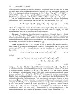
7.55).
The
details roll along inclined
plane
3 and
turn because
of the
difference
in
radii, becoming sorted into
two
lines
of
details, depending
on the
side
to
which radius
r
faces.
The
curvative
of the
trajectory
is
L,
which
can be
calculated
from
the
following
formula:
The
two
rows
can be
merged later, when
the
parts
are
oriented.
Sometimes
the
device
for
active orientation
can
require
a
certain degree
of
sophisti-
cation;
for
instance,
the
orientation
of
rings with internal bevels
on one
side,
as in
Figure
7.56.
Rings
3 are
placed automatically
in the
channel
and
feeler
4 is
brought
in
contact
with each ring. Feeler
4 is
driven
by
lever
10 and
bushing
6,
which slides
in
guide
7. If
the
bevel
faces
the
right side
of the
ring,
feeler
4
penetrates deeper into
it and
screw
8,
which
is
fastened onto feelers
rod 12,
presses
microswitch
9,
thus
energizing
elec-
7.9
Logical
Orientation
271
FIGURE
7.55
Active
orientation
of
rolling
conical
details
(orientation
due to
difference
in
radii).
FIGURE
7.56
Active
orientation
of
rings
with
one
internal
bevelled
face.
tromagnet
2 and
putting
the
directing blade into
the
appropriate position,
say
B.
If
the
bevel
faces
left
(as in
Figure
7.56),
feeler
4
penetrates less
and
compresses spring
5
while screw
8
does
not
reach
microswitch
9.
Magnet
11
is
then
activated, changing
the
position
of
blade
1 so as to
direct
the
ring into channel
A.
7.9
Logical
Orientation
As
was
mentioned earlier, every detail
we
deal with
has a
certain number
of
stable
positions
on the
tray.
Usually,
one
position
is
desired
and the
others must
be
driven
into
the
desired
position
by
forcing
the
detail
to
turn around coordinate axes.
The
desired position
of an
item
can be
described
by
some events which must happen.
For
instance,
an
asymmetrical item must
lie on a
certain side (event
a),
with
a
certain
cutout
facing
in a
given direction (event
b). The
correctly oriented item
is,
thus,
an
event
c
which
is a
logical
function
of two (or
more)
logical variables
a and b.
This state-
ment
can be
written
in
terms
of
Boolean algebra
in the
following
forms:
272
Feeding
and
Orientation
Devices
This
operation
is
called conjunction
(logical
multiplication)
and
means:
statement
c
is
true when
and
only when both statements
a and b are
true. When
a and b
take place
we
write
Thus:
When
one or
both
of the
variables
are not
true
(a
- 0
and/or
b =
0),
the
result also
is
0 and
event
c
does
not
exist
(c
=
0).
It is
convenient
to use
inversion (another oper-
ation
in
Boolean algebra), i.e.,
the
opposite
of
the
variable's value. Thus, denial
a
means
not a.
When
a = 1 the
denial
a = 0. We can
write
In
performing
active orientation,
we
often
deal with only
two
possibilities,
one of
them
c = a and the
other
c = a. For
example,
a
device
for
active orientation
of
disclike
details, which have
one
smooth side
I and
another side
II
with
a
certain degree
of
roughness,
is
shown
in
Figure 7.57.
The
sensor
is
pneumatic.
Its
nozzle
4 is
placed
at
distance
h
from
detail
3. The
pressure
to
which sensor
5
responds depends
on the
smoothness
of the
detail's
surface
under
the
nozzle (the smoother
the
surface,
the
lower
the
pressure
in the
sensor).
In
effect,
the
control unit solves
the
logical task:
• The
pressure
in
sensor
5 is
low: then
the
detail continues
from
table
2 to
tray
7.
• The
pressure
in
sensor
5 is
high:
then
the
detail
is
lowered
by
means
of an
elec-
tromagnet
(controlled
by
unit
6) and the
detail
continues
to
tray
8.
Thus,
the
details
on
trays
7 and 8 are
oriented oppositely.
Another
example
is
shown
in
Figure
7.58.
Here
a
flat
detail with
an
asymmetric cutout
is
actively oriented.
The
details move
in
positions
I or II
along tray
3.
Light
source
1
and
lens
2
project
an
image
of
these
parts onto screen
5,
which
is
placed
behind
diaphragm
4, and
actuate photocells
6 or 7. In
accordance with these signals,
the
logical
decision
is
made
and
rotary gripper
8
brings
the
detail into
the
desired position.
A
more complicated example
is
illustrated
in
Figure 7.59.
Again,
a flat
detail
is
con-
sidered; however, here
four
positions
are
possible.
As it
follows
from
Figure 7.59,
three
FIGURE
7.57
Pneumatic
device
for
active
orientation
of
flat
detail with
one
rough
side.
7.9
Logical
Orientation
273
FIGURE
7.58
Photoelectric
device
for
active
orientation
of
asymmetrical,
flat
detail.
FIGURE
7.59
Device
for
logical
active
orientation
of
asymmetrical
flat
detail:
a)
Possible positions
of the
detail;
b)
The
repositioning
device.
contacts
1,2,
and 3
make
the
following
four
connections when
the
detail being oriented
touches them
in the
various orientations:
1-2-3
events
<2,fe,c,d
1-3
events
b,
0,c,
rf
1-2
events
c,d,a,b
2-3
events
d,a,b,c
The
logical orientation system must
be
able
to
bring
the
detail into
the
desired posi-
tion
from
any
other. This means,
for
instance,
that
if
the
desired position
is "a" and the
detail
is in
state "b,"
the
contact with point
2 is
lacking. This
can be
corrected
by
rotat-
ing
180° around
the
Z-axis.
For
state
"c" to be
brought into
the
desired state,
one
must
rotate
the
detail around
the
X-axis
180°.
State
"d" can be
brought
to
situation
"a" by
rotating
around
the
F-axis
180°.
Alternatively,
the
same
effect
can be
achieved
by two
consecutive rotations around
the Z-
and
X-axes
(both
for
180°).
Figure
7.59b)
shows
a
plan
of a
device
for
this kind
of
manipulation.
The
detail
is
inserted
into
the
in
shaft
12.
This
shaft
is
installed
in
bushing
13 and
rotates around
the
X-axis.
The
bushing,
due to
shaft
4
supported
by
bearing
14,
rotates around
the
Z-axis.
Shaft
12 is
driven
by
bevel
gears
5 and 6.
Wheel
6 is
connected
to
pinion
8.
Stop
7
provides rotation
for
exactly
180°.
The
continuation
9 of
shaft
4 has
pinion
10,
which
is
braked
by
means
of
274
Feeding
and
Orientation
Devices
stop
11.
According
to the
logical
function
denned
by
contacts
1, 2, and 3, the
control
unit processes commands
to
motors (not shown
in the figure),
driving
pinions
8 and
10
so as to
bring
the
detail into
the
required position.
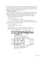
7.10
Orientation
by
Nonmechanical Means
We
discuss
here some
ideas
based
on the use of
electromagnetic
fields for
orien-
tation. Figure 7.60 shows
a
classification
of the
different
combinations
of
materials
and
electromagnetic
fields
that
are
used.
We
will
present some examples relevant
to
elec-
trostatic, magnetostatic,
and
alternating magnetic
fields
(some other special cases
are
omitted)
in
combination with parts made
of
ferromagnetic
or
nonmagnetic conduc-
tors
or
dielectric materials.
The
diagram
in
Figure 7.60 indicates that:
• An
electrostatic
field is
useful
for
orientation
of
oblong
items
made
of any
material;
• A
magnetostatic
field is
useful
mainly
for
orientation
of
items made
of
ferro-
magnetic materials;
• An
alternating magnetic
field can be
used
for
orienting items made
of
non-
magnetic electricity conductors.
Where
do we use
these orientation approaches? What
are
their main properties?
These
are
noncontact methods
of
orientation. Theoretically, orientation could
be
carried
out in a
vacuum, manipulating
the
detail while
it is
suspended
by the
forces
set up by the field.
I-Ferromagnetic
conductive
material
2-Nonmagnetic
conductive
material
3-Dielectric
materials
FIGURE
7.60
Classification
of
electromagnetic
fields in
combination
with
materials
of
different
natures.
7.10
Orientation
by
Nonmechanical
Means
275
•
These
are
active methods
of
orientation.
If
properly designed,
the
devices cre-
ating
the field can
bring
the
details
or
elements into
the
desired position regard-
less
of
their previous position.
•
This orientation method
is
convenient
for
details with slight
or
negligible asym-
metries
in
external shape
or
with
specific
internal features.
Let
us
begin
our
consideration with
an
illustration describing
the use of a
magne-
tostatic
field
(permanent magnetic
field). As was
mentioned earlier, this kind
of field
is
effective
for
ferromagnetic items. Figure 7.61 shows examples
of
details with inter-
nal and
external asymmetry,
and
Figure 7.62 shows
a
coil
2
creating
a
permanent
mag-
FIGURE
7.61
Examples
of
ferromagnetic
details with
either
internal
or
slight external
asymmetry
suitable
for
active orientation
by a
magnetostatic
field.
FIGURE 7.62
Diagram
of an
active orientation device
for the
details shown
in
Figure
7.61.
276
Feeding
and
Orientation
Devices
netic
field
suitable
for
such details.
The
diagram also shows
the
balance
of
forces
appearing
when
the
detail
is put
into
the
coil. There
is a
difference
between
the
forces
F
A
and
F
B
when
the
detail
is
placed symmetrically
in the
coil. This results
in
displace-
ment
of the
detail
so
that
the
distances
/j
and
1
2
are not
equal:
This
difference
is
enough
to be
used
for
active orientation.
Figure
7.63 illustrates
a
dielectric part (clamp-shaped, with
a
slight
difference
between
the
ends,
as
shown
in
part
c) of the figure)
being
oriented
by
means
of an
electrostatic
field. The field is
created between
the
pair
of
electrodes
1. The
parts
2
move
from
the
left
to the
right and, whatever their orientation
I
before
they enter
the
field, the
interaction between
the field and the
parts brings them into position
II,
where
the
thick
end of the
part
faces
forward.
Section
b) of
Figure 7.63 shows
the
creation
of
a
torque
T due to the
difference
between
forces
F
l
and
F
2
appearing because
of the
nonuniformity
of the
electrostatic
field at the
entrance into
the
space between
the
electrodes.
By
appropriately designing
the
shapes
and
relative locations
of the
elec-
trodes, active orientation
of
dielectric parts
can be
achieved.
Another
example
of
this
sort
is
presented
in
Figure 7.64. Here electrodes
1
create
a
nonuniform
field
because
of the
wedge-like space between them. Such
a field
causes
rotation
of
parts
2
from
position
I
into position
II. In
addition,
the
parts
will
stop
in
position
III in the
narrowest section
3 of the field,
which situation provides coinci-
dence
of the
maximum value
of
dielectric permittivity with
the
direction
of
maximum
field intensity.
The
forces
developed
by the field are
usually small;
therefore,
resistance caused
by
friction
or
other
factors
must
be
minimal when using this kind
of
orientation.
The
smaller
the
part,
the
higher
are the
effects.
One
specific
example
can
emphasize this
point. This
is a
process
for
producing imitation velvet, which
is
widely used
for
deco-
ration.
The
process consists
of
glueing short-cut silk
fibers to the
surface
of
paper,
fabric,
board, etc.,
and is
carried
out by an
automatic machine,
the
design
of
which
is
presented
in
Figure
7.65.
The
fabric
(or
paper
or
whatever)
2 is
transported through
FIGURE
7.63
Active
orientation
in an
electrostatic
field: a)
Behavior
of
details
on
the
tray;
b)
Forces
and
torques acting
on
the
detail;
c)
Representative details.
7.10
Orientation
by
Nonmechanical
Means
277
FIGURE
7.64 Active orientation
in an
electrostatic
field of a
cylindrical
detail
having
internal
features.
FIGURE
7.65 Design
of an
automatic
machine
for
producing imitation velvet.
(Electrostatic
field is
used
for
orientation
of
short silk
threads.)
the
machine
from
roll
1 to
roll
10,
supported
by
rollers
3.
Roller
4
deposits glue
on the
lower
surface
of
the
fabric.
The
glue
is
applied
to
roller
4 by
rollers
5,
which take
it
from
glue
pan 6. The cut
silk
fiber
(previously dried)
11
is
supplied
from
hopper
13 by
con-
veyor
belt
8,
which
is
driven
by
rollers
12. The
main purpose
of
this machine
is to
stick
the cut fibers
upright
to the
surface
of
the
fabric
(paper, board,
etc.),
as
shown
in
Figure
7.65a).
It
seems that
the use of an
electrostatic
field is the
only industrially relevant
solution.
The field
orients every single piece
of fiber
along
the field
lines
and
moves
them
from
one
electrode
7
toward
the
other.
After
the fiber is
stuck,
the
product
is
dried
in
dryer
9. The
voltage used between
the
electrodes
7 is
about 10,000-15,000
V
278
Feeding
and
Orientation
Devices
An
alternating magnetic
field is a
means
for
orienting
nonferromagnetic
parts made
of
electrically conducting
materials.
The
physical phenomenon exploited here
is the
interaction between
the
magnetic
field and
eddy currents induced
in the
parts
by the
alternating
field.
Figure 7.66 shows
the
orientation
of
metal
details
having slight dif-
ferences
in
shape
at
their ends, such
as
threading, small holes,
or
cutouts, etc.
The
electrodynamic
forces
F
{
and
F
2
appearing here create
a
torque
T
which turns
the
part
on the
tray.
The
inequality
F
l
>
F
2
is
caused
by the
difference
in the
currents
i
v
>
i
2
,
which
is
due to the
slight
differences
in
shape between
the two
ends
of the
part.
As a
result,
the
part
is
brought
from
position
I
into position
II,
with
the
rough (thread
or
knurling)
end
forwards.
It
is
worthwhile
to
mention here that orienting
of
these kinds
of
parts
by
mechan-
ical means requires
a lot of
effort
(if
it is
even
possible).
To
illustrate this,
we
show here
the
means
to
orient
a
part
(a
stud)
of the
type shown
in
Figure
7.66.
A
mechanical solu-
tion
is
presented
in
Figure
7.67.
The
detail
is
caught
by two
clamps
2.
Knife
3
strikes
the
middle
of the
stud. Because
the
friction
in the
clamp where
the
threatened
end of
the
stud
is
located
is
higher, this
end
will
be
freed
later. Thus,
the
stud
falls
with
the
smooth
end
downward into guide
4.
An
alternating magnetic
field
acting
on
angle pieces develops
forces
as
shown
in
Figure 7.68.
The
resulting
force
5AF
rotates
the
part
from
every
position
I
into
the
desired position
II,
with
the
vertical side
facing
backward.
The
values
of the
forces
in
such
cases
depend
upon:
• The
intensity
of the field,
• The
frequency
of the
alternating
field,
• The
shape
of the
detail being manipulated,
• The
material
of
which
the
detail
is
made,
and
• The
dimensions
and
shape
of the
detail.
This chapter
is
largely
based
on the
valuable material presented
in the
excellent
book
by
Prof.
A.
Rabinovich,
Automatic Orientation
and
Feeding
ofPiecelike
Details
(Technika,
Kiev,
1968)
(in
Russian),
and the
book
by
I.
Grinshtein
and
E.
Vaisman,
Auto-
FIGURE
7.66
Active
orientation
of
asymmetrical
details
in an
alternating
magnetic
field:
a)
Representative
details;
b)
Behavior
of the
details
on the
tray;
c)
Forces
and
torques acting
on the
details.
Exercises
279
FIGURE
7.67 Mechanical
orientation
of a
stud.
FIGURE
7.68 Active
orientation
of an
angle
piece
by an
alternating
magnetic
field.
matic Feeding Systems
in the
Instrument Construction Industry
(Mashinostrojenie,
Moscow,
1966)
(in
Russian).
A
book relevant
to the
subject
of
orientation
by
means
of
electromagnetic
fields is
that
by Dr. B.
Yoffe
and R. K.
Kalnin:
Orientation
of
Parts
by
Electromagnetic
Fields
(Zinatne,
Riga,
1972)
(in
Russian).
Exercise
7E-1
A
strip-feeding device
is
shown
in
Figure 7E-1.
The
thickness
of
the
strip
h =
0.004
m,
and the
force
needed
to
move
it
F=
100 N.
Other dimensions indicated
in the
figure
have
the
following values:
L
=
0.1
m,
/
=
0.05
m, and
H=
0.06
m.
What
is the
force
Q
280
Feeding
and
Orientation Devices
that
the
spring must develop
to
provide reliable functioning
of the
device? What
are
the
reactions
R
x
and
R
y
at
point
O? The
friction
coefficient
//
=
0.15.
FIGURE
7E-1
Exercise
7E-la)
One
of the two
elements
of a
ribbon feeder
is
shown
in
Figure
7E-la).
The
spring
in
it
develops
a
force
F=
20 N. The
spring acts
on two
rollers which,
due to the
shape
of
the
device, create
a
friction
force
between
the
ribbon (point
B) and the
rollers
and
the
inner inclined
surface
of the
housing (point
A).
The
inclination angle
=
15°,
and
the
coefficient
of
friction
fj.
=
0.3. What
is the
pulling
force
Q
that this device
is
able
to
develop?
FIGURE
7E-1a)
Exercise
7E-lb)
A
vertical
rod-feeding
mechanism
is
shown
in
Figure
7E-lb).
The
mechanism
acts
as a
result
of the
friction
forces
developing between
the fed rod and the
gripping jaws.
The
weight
of the
levers holding
the
jaws
P = 0.8 N, the
weight
of the
feed
rod Q = 40 N,
and the
friction
coefficient
ju
=
0.4. Find
the
value
A
that provides
the
normal
feeding
process
of the
mechanism
if
H=
80 mm and h = 20 mm.
Exercises
281
FIGURE
7E-1b)
Exercise
7E-2
Calculate
the
displacement
H per
second
of a
part placed
on the
groove
of a
spi-
rally
vibrating bowl, such
as in
Figure 7E-2,
of a
vibrofeeder.
Pertinent data
for the
feeder
are
clear
from
Figure 7E-2:
Inclination angle
of the
groove
a = 2°,
Slope
angle
of the
springs
7 =
30°,
Coefficient
of
friction
between
the
groove
and the
feed
part
ju
=
0.6,
Frequency
of
vibration/=
50 Hz, and
Amplitude
of the
harmonic vibration
a = 0.1 mm.
FIGURE
7E-2
Exercise 7E-3
This
is the
same exercise
as
that
in the
previous case (Exercise
7E-2)
except
that
the
amplitude
of
vibration
is
increased
to a
value
of
a =
0.15
mm.
282
Feeding
and
Orientation
Devices
Exercise 7E-4
How
many
stable
modes
on the
tray
of a
feeder
can the
part shown
in
Figure 7E-4
have when:
H=B;
H*B;
h =
HI2;and
h
*
HI2?
FIGURE
7E-4
Exercise 7E-5
How
many stable modes
on the
tray
of a
feeder
can the
part shown
in
Figure 7E-5
have when:
H=B =
L;
H*B
=
L;and
H*B*L1
FIGURE
7E-5
8
Functional Systems
and
Mechanisms
8.1
General
Concepts
In
the
previous
six
chapters
we
have discussed
the
problem
of
automatic manu-
facturing
of
products, describing common
features,
approaches, systems, devices,
and
mechanisms typical
for the
kind
of
equipment used.
Now we
must turn
to the
specific
elements that make every machine
useful
for a
specific
task
(or a
group
of
specific
tasks).
The
means that carry
out
these
tasks
or
processes will
be
called functional
systems
and
mechanisms.
The
list
of
such processes
is
endless,
as is the
list
of
systems
and
mechanisms
to
carry them out. Some processes used
in
automatic manufactur-
ing
are:
Metal
cutting,
Molding
of
metals
and
plastics,
Stamping,
Assembling,
Coloring,
Galvanic
coating
and
plating,
Measuring,
controlling,
and
sorting,
and
Chip
technologies.
The
processes listed here
can be
subdivided
further.
For
instance, metal cutting
includes
the
following
operations:
•
Turning,
•
Milling,
283
284
Functional Systems
and
Mechanisms
•
Drilling,
•
Threading,
•
Counterboring,
countersinking,
and
•
Reaming.
Further classification
is
possible even
at
this level.
For
example, there
are
several
methods
for
carrying
out the
process
of
threading. Indeed,
we can
distinguish between:
•
Chase-threading
or
thread-chasing,
•
Single-point-tool threading,
and
•
Threading
by
screw tap.
The
analysis
can
often
continue
to
even lower
sublevels.
Our
purpose
in
this
listing,
however,
is to
show that
an
attempt
to
cover
the
ocean
of
automatic means
of
accom-
plishing
all the
possible manufacturing tasks within
the
limits
of a
chapter
(or
even
a
book)
is not
realistic.
Therefore,
we
discuss here only some selected examples, with
the
emphasis
on
assembling because
this
is an
important
stumbling-block
in
auto-
matic manufacturing today.
8.2
Automatic Assembling
Assembly
accounts
for
about
50 to 60% of the
workload
in
machine building
and
apparatus building.
In
some
fields
this percentage
is
even higher.
For
instance,
in the
electronics industry assembly includes chip production, circuit production,
and
man-
ufacture
of the final
product.
The
high relative importance
of
assembly
in
manufac-
turing makes
the
need
for
automation
of
these processes crucial.
Every
success
in
automating
the
assembling process results
in
considerable
profit.
There
are
many kinds
of
assembly techniques used
in
industry, and, obviously,
the
methods
for
automation
for
each
of
them must also
differ.
A
brief list
of
these tech-
niques
follows:
1.
Mechanical assembly with fastening
by:
screws, rivets, stamping, binding,
expanding,
and
forge-rolling.
2.
Welding:
arc
welding
of
various kinds,
gas
welding, seam resistance welding,
butt
resistance
welding,
and
resistance spot welding.
3.
Soldering
and
brazing: ultrasonic soldering,
flow
soldering
or
brazing, salt-bath
drip brazing,
and
metal
dip
brazing.
4.
Bonding with glues, resins,
and
adhesives.
5.
Sewing
or
stapling with: threads, wires, clips, clamps, etc.
6.
Magnetic mounting, twisting, curling, coiling, interference
fit,
slide
fit,
wedge-
insertion, spring catch (latch, pawl,
trip).
The
assembly process, whatever
its
nature, consists
of a
number
of
operations.
Two
operations that
are
almost always needed
in
assembly
are
alignment
and
control—for
instance, control
for the
presence
of
needed parts, quality control, etc.
The
next oper-
ation
is
completion
of
the
assembly, which requires
appropriate
tools
and
actions.
The
operations needed
for
direct preparation
for
assembly (orientation
of
details, coating
with
glue,
tin-plating, etc.) also depend
on the
nature
of the
whole process.
A
simpli-
fied
example
of
assembly, illustrating this general description,
is
shown
in
Figure
8.1.