Máy đào HuynDai R170W-9 (Phần 1) - P4
Bạn đang xem bản rút gọn của tài liệu. Xem và tải ngay bản đầy đủ của tài liệu tại đây (305.42 KB, 4 trang )
3-29
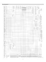
The oil from the A1 and A2 pump flows through the neutral oil passage, bypass oil passage and
confluence oil passage in the main control valve. Then the oil goes to each actuator and operates
them. Check valves and orifices are located on these oil passage in the main control valve. These
control the oil from the main pumps so as to correspond to the operation of each actuator and
smooth the combined operation.
1. OUTLINE1. OUTLINE
B1
A1
A2
B2
P
T2
T4(TGP)
ACC1GP
BR1
BR2
ACC2
ACC1
CT4
P
PGP
CT3
CT1
CT2
dr3
dr2
BRAKE VALVE
ARM
CYLINDER
BUCKET
CYLINDER
TRAVEL MOTOR
FRONT AXLE
REAR AXLE
OSCILLATING
CYLINDER
TRANSMISSION
SWING MOTOR
TURNING
JOINT
BOOM CYLINDER
TP
M2
P
T
P
T
M
K
B
AC1
T3
P1
P1P2
L R
M1
Pu
Pc42
Pb3
Pd41
DR1
Pb21
Pb20
Pa20
Pb1
Pa1
T1
Pc3
Pa21
V3
Pd2
D2
C2
Pc1
D1
C1
Pd1
Ai
B4
B5
A5
Pa5
Pb5
Pa4
Pb4
C5
D5
D4
C4
Pc40
Pd40
DR3
Pc5
Pd5
Rs
C6
D6
P03
PS
P1P2
P3
P0
Patt
P02
PS
Pn1
Pi1(Pump)
Pi2(Pump)
Pn2
PS
PS
Pd6
Pc6
PS
Pc2
P05
Puo
Pc41
DR5
DR2
DR4
DR0
SH
(S/Motor)
ARM 1
BOOM 2
SWING
TRAVEL
OPT-C
BOOM 1
ARM
REGEN
BUCKET
OPT-B
DOZER
ARM 2
HYDRAULIC TANK
DOZER/ OUTRIGGER CYLINDER
PILOT
PUMP
A1
PUMP
A2
PUMP
P04
GROUP 5 COMBINED OPERATIONGROUP 5 COMBINED OPERATION
17W93HC23
3-30
When the swing and boom up functions are operated, simultaneously the swing spool and boom
spools in the main control valve are moved to the functional position by the pilot oil pressure from the
remote control valve.
The oil from the A1 pump flows into the swing motor through swing spool and the boom cylinder
through boom 2 spool.
The oil from the A2 pump flows into the boom cylinders through the boom 1 spool in the right control
valve.
The super structure swings and the boom is operated.
Refer to page 3-13 for the boom priority system.
2. COMBINED SWING AND BOOM UP OPERATION2. COMBINED SWING AND BOOM UP OPERATION
B1
A1
A2
B2
P
T2
T4(TGP)
ACC1GP
BR1
BR2
ACC2
ACC1
CT4
P
PGP
CT3
CT1
CT2
dr3
dr2
BRAKE VALVE
ARM
CYLINDER
BUCKET
CYLINDER
TRAVEL MOTOR
FRONT AXLE
REAR AXLE
OSCILLATING
CYLINDER
TRANSMISSION
SWING MOTOR
TURNING
JOINT
BOOM CYLINDER
TP
M2
P
T
P
T
M
K
B
AC1
T3
P1
P1P2
L R
M1
Pu
Pc42
Pb3
Pd41
DR1
Pb21
Pb20
Pa20
Pb1
Pa1
T1
Pc3
Pa21
V3
Pd2
D2
C2
Pc1
D1
C1
Pd1
Ai
B4
B5
A5
Pa5
Pb5
Pa4
Pb4
C5
D5
D4
C4
Pc40
Pd40
DR3
Pc5
Pd5
Rs
C6
D6
P03
PS
P1P2
P3
P0
Patt
P02
Pn1
Pi1(Pump)
Pi2(Pump)
Pn2
PS
PS
Pd6
Pc6
PS
Pc2
P05
Puo
Pc41
DR5
DR2
DR4
DR0
SH
(S/Motor)
ARM 1
BOOM 2
SWING
TRAVEL
OPT-C
BOOM 1
ARM
REGEN
BUCKET
OPT-B
DOZER
ARM 2
HYDRAULIC TANK
DOZER/ OUTRIGGER CYLINDER
PS
PILOT
PUMP
A1
PUMP
A2
PUMP
P04
17W93HC24
3-31
When the swing and arm functions are operated, simultaneously the swing spool and arm spools in
the main control valve are moved to the functional position by the pilot oil pressure from the remote
control valve.
The oil from the A1 pump flows into the swing motor through swing spool and the arm cylinder
through arm 1 spool.
The oil from the A2 pump flows into the arm cylinder through the arm 2 spool of the right control
valve.
The super structure swings and the arm is operated.
Refer to page 2-35 for the swing operation preference function.
3. COMBINED SWING AND ARM OPERATION3. COMBINED SWING AND ARM OPERATION
B1
A1
A2
B2
P
T2
T4(TGP)
ACC1GP
BR1
BR2
ACC2
ACC1
CT4
P
PGP
CT3
CT1
CT2
dr3
dr2
BRAKE VALVE
ARM
CYLINDER
BUCKET
CYLINDER
TRAVEL MOTOR
FRONT AXLE
REAR AXLE
OSCILLATING
CYLINDER
TRANSMISSION
SWING MOTOR
TURNING
JOINT
BOOM CYLINDER
TP
M2
P
T
P
T
M
K
B
AC1
T3
P1
P1P2
L R
M1
Pu
Pc42
Pb3
Pd41
DR1
Pb21
Pb20
Pa20
Pb1
Pa1
T1
Pc3
Pa21
V3
Pd2
D2
C2
Pc1
D1
C1
Pd1
Ai
B4
B5
A5
Pa5
Pb5
Pa4
Pb4
C5
D5
D4
C4
Pc40
Pd40
DR3
Pc5
Pd5
Rs
C6
D6
P03
PS
P1P2
P3
P0
Patt
P02
PS
Pn1
Pi1(Pump)
Pi2(Pump)
Pn2
PS
PS
Pd6
Pc6
PS
Pc2
P05
Puo
Pc41
DR5
DR2
DR4
DR0
SH
(S/Motor)
ARM 1
BOOM 2
SWING
TRAVEL
OPT-C
BOOM 1
ARM
REGEN
BUCKET
OPT-B
DOZER
ARM 2
HYDRAULIC TANK
DOZER/ OUTRIGGER CYLINDER
PILOT
PUMP
A1
PUMP
A2
PUMP
P04
17W93HC25
3-32
When the swing and bucket functions are operated, simultaneously the swing spool and bucket
spool in the main control valve are moved to the functional position by the pilot oil pressure from the
remote control valve.
The oil from the A1 pump flows into the swing motor through the swing spool in the left control valve.
The oil from the A2 pump flows into the bucket cylinder through the bucket spool in the right control
valve.
The super structure swings and the bucket is operated.
4. COMBINED SWING AND BUCKET OPERATION4. COMBINED SWING AND BUCKET OPERATION
B1
A1
A2
B2
P
T2
T4(TGP)
ACC1GP
BR1
BR2
ACC2
ACC1
CT4
P
PGP
CT3
CT1
CT2
dr3
dr2
BRAKE VALVE
ARM
CYLINDER
BUCKET
CYLINDER
TRAVEL MOTOR
FRONT AXLE
REAR AXLE
OSCILLATING
CYLINDER
TRANSMISSION
SWING MOTOR
TURNING
JOINT
BOOM CYLINDER
TP
M2
P
T
P
T
M
K
B
AC1
T3
P1
P1P2
L R
M1
Pu
Pc42
Pb3
Pd41
DR1
Pb21
Pb20
Pa20
Pb1
Pa1
T1
Pc3
Pa21
V3
Pd2
D2
C2
Pc1
D1
C1
Pd1
Ai
B4
B5
A5
Pa5
Pb5
Pa4
Pb4
C5
D5
D4
C4
Pc40
Pd40
DR3
Pc5
Pd5
Rs
C6
D6
P03
PS
P1P2
P3
P0
Patt
P02
PS
Pn1
Pi1(Pump)
Pi2(Pump)
Pn2
PS
PS
Pd6
Pc6
PS
Pc2
P05
Puo
Pc41
DR5
DR2
DR4
DR0
SH
(S/Motor)
ARM 1
BOOM 2
SWING
TRAVEL
OPT-C
BOOM 1
ARM
REGEN
BUCKET
OPT-B
DOZER
ARM 2
HYDRAULIC TANK
DOZER/ OUTRIGGER CYLINDER
PILOT
PUMP
A1
PUMP
A2
PUMP
P04
17W93HC26