Máy đào HuynDai R170W-9 (Phần 2) - Chapter 3
Bạn đang xem bản rút gọn của tài liệu. Xem và tải ngay bản đầy đủ của tài liệu tại đây (434.08 KB, 8 trang )
4-24
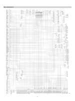
GROUP 3 ELECTRICAL COMPONENT SPECIFICATIONGROUP 3 ELECTRICAL COMPONENT SPECIFICATION
1
C
ST
ACCBR
H
B
2
4
H
I
0,
I
0
3
5
6
5
4
3
2
1
6
CS-2
C
B
A
SUPPLY
SIG
RETURN
CD-7 CD-24 CD-31
CD-35 CD-38 CD-42
CD-44 CD-69 CD-70
CD-74
CD-3 CD-4 CD-5
CD-32
CD-43
CD-73
CD-6
A
B
C
A
B
CN-173
CR-1
CR-24
Part name Symbol Specifications Check
Battery
12V
×
100Ah
(2EA)
※
Check specific gravity
1.280 over : Over charged
1.280 ~ 1.250 : Normal
1.250 below : Recharging
Battery relay
Rated load :
24V
100A (continuity)
1000A
(30seconds)
※
Check coil resistance(M4 to M4)
Normal : About 50
Ω
※
Check contact
Normal :
∞Ω
Glow plug relay 24V 200A
※
Check contact
Normal : 0.942
Ω
(For terminal 1-GND)
Start key
B-BR : 24V 1A
B-ACC : 24V 10A
B-ST : 24V 40A
※
Check contact
OFF :
∞Ω
(for each terminal)
ON : 0
Ω
(for terminal 1-3 and 1-2)
START : 0
Ω
(for terminal 1-5)
Pressure sensor 8~30V
※
Check contact
Normal : 0.1
Ω
Resistor 4W
※
Check resistance
A-B : 120
Ω
4-25
Part name Symbol Specifications Check
Glow plug 24V 200A
※
Check resistance
0.25~0.12
Ω
Temperature
sensor
(hydraulic)
-
※
Check resistance
50
˚
C : 804
Ω
80
˚
C : 310
Ω
100
˚
C : 180
Ω
Air cleaner
pressure switch
(N.O TYPE)
※
Check contact
High level :
∞Ω
Low level : 0
Ω
Fuel sender -
※
Check resistance
Full : 50
Ω
6/12 : 350
Ω
11/12 : 100
Ω
5/12 : 400
Ω
10/12 : 150
Ω
4/12 : 450
Ω
9/12 : 200
Ω
3/12 : 500
Ω
8/12 : 250
Ω
2/12 : 550
Ω
7/12 : 300
Ω
1/12 : 600
Ω
Empty warning : 700
Ω
Relay
(air con blower,
head lamp,
cabin lamp,
fuel heater)
24V 20A
※
Check resistance
Normal : About 200
Ω
(for terminal 1-3)
0
Ω
(for terminal 2-4)
Relay 24V 16A
※
Check resistance
Normal : About 160
Ω
(for terminal 1-2)
0
Ω
(for terminal 3-4)
∞Ω
(for terminal 3-5)
1
2
CD-8
C
2
1
Pa
CD-2
CD-1
CD-10
CN-80
CR-4 CR-13 CR-14
CR-46 CR-78 CR-81
CR-82 CR-83 CR-84
1
2
3
4
3
1
2
4
1
2
3
4
5
2
1
5
3
4
CR-5 CR-12 CR-15
CR-36 CR-45 CR-62
CR-63 CR-66
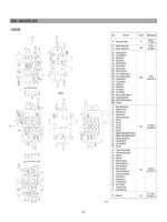
4-26
Part name Symbol Specifications Check
Replay 24V 200A
※
Check resistance
0.25~0.12
Ω
Solenoid valve -
※
Check resistance
50
˚
C : 804
Ω
80
˚
C : 310
Ω
100
˚
C : 180
Ω
Air cleaner
pressure switch
(N.O TYPE)
※
Check contact
High level :
∞Ω
Low level : 0
Ω
Fuel sender -
※
Check resistance
Full : 50
Ω
6/12 : 350
Ω
11/12 : 100
Ω
5/12 : 400
Ω
10/12 : 150
Ω
4/12 : 450
Ω
9/12 : 200
Ω
3/12 : 500
Ω
8/12 : 250
Ω
2/12 : 550
Ω
7/12 : 300
Ω
1/12 : 600
Ω
Empty warning : 700
Ω
Relay
(air con blower)
24V 20A
※
Check resistance
Normal : About 200
Ω
(for terminal 1-3)
0
Ω
(for terminal 2-4)
Relay 24V 16A
※
Check resistance
Normal : About 160
Ω
(for terminal 1-2)
0
Ω
(for terminal 3-4)
∞Ω
(for terminal 3-5)
1
2
CN-75 CN-133 CN-238
CN-239 CN-240 CN-241
CN-242 CN-246
87a
30
87
85
86
87a
85
87
86
30
CR-2 CR-7 CR-9
CR-29 CR-30
CR-47 CR-79
CR-35
1
2
CN-68 CN-69 CN-70
CN-122 CN-123 CN-128
CN-140 CN-149 CN-153
CN-88
CN-135
CN-154
CN-181 CN-206 CN-214 CN-216
CN-220 CN-236 CN-237
3
7
12
11
3
4
5
6
7
8
9
10
11
12
4
8
10
9
2
1
12
2
CS-23 CS-52 CS-67
CS-82 CS-83 CS-99
CS-79
CS-100
1
2
CN-23(LH)
CN-24
(RH)
S
+
-
A
B
C
CN-142
4-27
Part name Symbol Specifications Check
Room lamp 24V 10W
※
Check disconnection
Normal : 1.0
Ω
ON : 0
Ω
(For terminal 1-2)
∞Ω
(For terminal 1-3)
OFF :
∞Ω
(For terminal 1-2)
0
Ω
(For terminal 1-3)
Work lamp,
Cab lamp,
Number plate
lamp
24V 65W
(H3 Type)
※
Check disconnection
Normal : 1.2
Ω
Beacon lamp
21V 70W
(H1 Type)
※
Check disconnection
Normal : A few
Ω
Fuel filler pump
24V 10A
35
ℓ
/min
※
Check resistance
Normal : 1.0
Ω
Service meter 16 ~ 32V
※
Check operation
Supply power(24V) to terminal
No.2 and connect terminal
No.1 and ground
Horn
DC22 ~ 28V
2A
※
Check operation
Supply power(24V) to each
terminal and connect ground.
1
2
CL-5 CL-6 CL-8
CL-9 CL-21
3
2
1
CL-1
1
2
M
CN-61
M
CL-7-
h
3
2
1
CN-48
CL-7
CN-20 CN-25
1
2
4-28
CS-20 CS-53
1
2
3
4
5
6
7
8
9
10
11
12
13
14
15
16
ACC
ILL-
GND
SPK FRT RH-
SPK FRT LH-
TEL MUTE
ANT 12V
BACK UP+
ILL+
NC
SPK FRT RH+
REMOCON+
REMOCON GND
SPK FRT LH+
NC
GND
CN-27
P
1
2
CN-29
CN-29
Part name Symbol Specifications Check
Safety switch
24V 15A
(N.C TYPE)
※
Check disconnection
Normal : 1.0
Ω
ON : 0
Ω
(for terminal 1-2)
∞Ω
(for terminal 1-3)
OFF :
∞Ω
(for terminal 1-2)
0
Ω
(for terminal 1-3)
Wiper cut switch
24V
(N.O TYPE)
※
Check contact
Normal : 0
Ω
(one pin to ground)
Receiver dryer
24V 2.5A
※
Check contact
Normal :
∞Ω
Radio &
CD/MP3 player
24V 2A
※
Check voltage
20~25V
(for terminal 1-3, 3-8)
Washer pump 24V 3.8A
※
Check contact
Normal : 10.7
Ω
(for terminal 1-2)
Wiper motor 24V 2A
※
Check disconnection
Normal : 7
Ω
(for terminal 2-6)
1
2
M
CN-22
4
6
5
3
2
1
2
3
4
5
6
M
CN-21
23
1
1
2
3
CS-4
CS-4 CS-20
CS-53