Máy đào HuynDai R250 - P2.2
Bạn đang xem bản rút gọn của tài liệu. Xem và tải ngay bản đầy đủ của tài liệu tại đây (2.23 MB, 26 trang )
2-21
GROUP 2 MAIN CONTROL VALVE
(PSP)
XBtl
XBs
XAa1
XBp2
XAtl
XAs
XAb2
XBa1
XBp1
CMR2
CMR1
Pz
Btl
Bs
SP
HEAD
Aa1
Ck1
Dr1
FL
FR
CSP
LCa1
Atl
As
CCb HV
ROD
Ba1
Dr2
R1
Pns
Dr6
TRAVEL
(L)
SWING
BOOM2
ARM1
PaL
Pns Dr6
PaL
Ck1
Dr3
Dr2
PG
MR
TS
R1
R2(P2)
Dr4
PbL
Ck2
XAtr
XAo
XAb1 XBk XBa2
TRAVEL
(R)
OPTION
BOOM1
BUCKET
ARM2
Dr4 PbL
Atr
CP2
C2
LCo
LCb1
LCk
LCa2
(Ao)
HEAD
Ab1
HEAD
Bk1
ROD
Bb1 Ak1
ROD
PBP
XBtr XBo
XBb1 XAk
XAa2
Btr
(Bo)
Dr3
FR
Ck1
Ck2
NR1
BC
A1
SP(B2)
STL
A2
BK B1 OP TR
PBP
FL
A
VIEW A
Ck1
P2
R2
Py
PH
Ck2
Dr4
P1
Dr3
Px
P1
TL S B2 A1 BC
TR OP B1 BK A2
C1
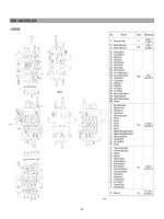
1. STRUCTURE
Port size Tightening torque
Mark
Port name
PF 1
PF 3/4
PF 3/8
PF 1/4
M10
M12
20~25
kgf・m
(115~180
lbf・ft
)
15~18
kgf・m
(109~130
lbf・ft
)
7~8
kgf・m
(50.6~57.8
lbf・ft
)
3.5~3.9
kgf・m
(25.3~28.2
lbf・ft
)
5~6.6
kgf・m
(36.1~47.7
lbf・ft
)
8.5~11.5
kgf・m
(61.5~83.1
lbf・ft
)
R1
Ck1
Ck2
XAtr
XBtr
XAo
XBo
XAk
XBk
XAb1
XBb1
XAa2
XBa2
XAtl
XBtl
XAs
XBs
XAa1
XBa1
XAb2
(Psp)
(XBp1)
(XBp2)
Pz
Py
PG
PH
Px
Dr1
Dr2
Dr3
Dr4
Dr6
FL
FR
Pns
PaL
PbL
PBP
Atr
Btr
(Ao)
(Bo)
Ak1
Bk1
Ab1
Bb1
Atl
Btl
As
Bs
Aa1
Ba1
P1
P2
R2
Make up port for swing
Bucket in confluence port
Bucket in confluence port
Travel right pilot port
Travel right pilot port
Option pilot port
Option pilot port
Bucket out pilot port
Bucket in pilot port
Boom up pilot port
Boom down pilot port
Arm in confluence pilot port
Arm out confluence pilot port
Travel left pilot port
Travel left pilot port
Swing pilot port
Swing pilot port
Arm in pilot port
Arm out pilot port
Boom up confluence pilot port
(Swing priority pilot port)
(Bucket in confluence pilot port)
(Drain port)
Main relief pilot pressure
Signal port for travel
Pilot pressure port
Pilot pressure port
Signal for other acutuators
Drain port
Drain port
Drain port
Drain port
Drain port
Negative control signal port(P1 port side)
Negative control signal port(P2 port side)
Swing logic valve pilot port
Lock valve pilot port
Lock valve pilot port
Drain port
Travel motor right side port
Travel motor right side port
Option port
Option port
Bucket rod side port
Bucket head side port
Boom head side port
Boom rod side port
Travel motor left side port
Travel motor left side port
Swing motor port
Swing motor port
Arm head side port
Arm rod side port
Pump port(P1 side)
Pump port(P2 side)
Return port
29072MC01
2-22
A
B
J
A
P1
TL
TR
S
OP
B2
B1
A1
BK
BC
A2
159
159
159
159
273
Pz
MR
TS
Dr2
NR2
R2(P2)
R1
Dr3
PaL
PbL
Dr4
Dr6
Pns
Px
PG
J
F
C
G
E
D
F
G
C
D
E
H
B
H
XAtl
XAs
XAb2
XBtl
XBs
(PSP)
(XBp2)
103
S
SWING
B2
BOOM 2
A1
ARM 1
SP
SWING PRIORITY
P1
TS
STRAIGHT
TRAVEL
TL
TRAVEL(L)
391
101
561153
XBa1
(XBp1)
XAa1
I
I
153
TS
MR
Pz
CMR1
CMR2
324
325
391
601
338
Ba1
A1
BC
HV
CCb
B2
A2
BK
B1
Ab1
Bk1
B2
A1
BC
B1
BK
A2
Aa1
Bb1
Ak1
J1
561
104
XAtr
XAo
XAb1
XAa2
XBtr
XBo
XBb1
XAk
XBa2
TR
TRAVEL(R)
OP
OPTION
B1
BOOM 1
BK
BUCKET
A2
ARM 2
K
L
R2
L
P2
K
XBk
974
976
975
102
164
154
K
1
158
357
NZy
NZx
357
CS2
CS1
PG
MN
M
N
SECTION A-A SECTION B-B
SECTION I-I
SECTION H-H
SECTION M-M SECTION N-N
975
101 Casing A
102 Casing B
103 Straight travel valve
104 Boom priority valve
153 Plug
154 Plug
155 Plug
158 Plug
159 Plug
164 O-ring
165 O-ring
166 O-ring
167 O-ring
168 O-ring
169 O-ring
201 Cover
202 Cover
203 Cover
204 Cover
207 Cover
209 Flange
251 Control valve assy
252 Lock valve assy
254 Swing logic valve assy
261 O-ring
262 O-ring
264 O-ring
273 Socket screw
301 Travel spool
302 Arm 1 spool assy
303 Boom 1 spool assy
304 Bucket spool
305 Swing spool
306 Arm 2 spool
307 Boom 2 spool
309 Spool(Option)
310 Travel spool
324 Spring
325 Spring
328 Spring
329 Spring
331 Spring seat
332 Spring seat
333 Bolt
334 Stopper
335 Stopper
336 Bolt
337 Stopper
338 Stopper
339 Stopper
357 Orifice
370 Spring
376 Spring
379 Spring
391 Straight travel spool
392 Bypass cut spool
395 Swing priority spool
401 Spool
424 Spring
425 Spring
438 Rod
511 Poppet
513 Poppet
515 Poppet
516 Poppet
521 Spring
522 Spring
523 Spring
551 Plug
552 Plug
553 Plug
554 Plug
555 Check valve assembly
556 Plug
561 O-ring
601 Main relief valve
602 Port relief valve
611 Nega-con relief valve
971 Socket screw
974 Socket screw
975 Socket screw
976 Socket screw
25072MC01
2-23
C2
164
154
521
C2
203
333
331
334
329
328
331
262
168
164
154
301
169
202
XAtr XAtl
Atr
Btr
TR TL
XBtr XBtl
203
333
331
334
329
328
331
262
166
165
165
515
521
551
561
310
165
169
202
203
333
331
334
329
328
331
262
553
561
971
165
209
511
521
551
561
971
165
209
309
561
553
169
202
201
336
332
335
379
370
332
261
159
166
166
165
165
254
251
165
305
264
204
XAo
XAs
159
AoR
(Ao)
LCo
(Bo)
As
Pns
Bs
XBs
XBo
BoR
OP S
166
379
370
332
261
159
602
159
252
165
552
523
561
516
165
551
561
511
303
165
264
602
204
201
336
332
335
207
336
332
339
379
370
332
261
307
165
561
551
521
511
561
551
521
511
551
561
395
261
332
370
376
339
332
336
207
XAb1
XAb2
Ab1R
B2
Ab1
LCb
Bb
Bb1R
XBb1
B1 SP
(PSP)
CCb
CSP
SP
201
332
336
335
370
379
332
261
602
166
513
522
561
554
304
602
201
332
336
335
379
370
332
261
602
252
516
523
552
561
511
521
551
561
302
264
204
602
XBk XBa1
BkR
Ba1R
Bk1
Ck2
Ak1
HV
LCa1
Aa1
AkR
XAk
BK A1
XAa1
Aa1R
201
336
332
335
379
370
332
261
165
551
561
306
165
203
333
331
337
329
328
331
262
392
551
561
611
165
555
611
551
169
202
264
204
XBa2
XBp1
Dr2
NR2
F
R
F
L
Ck1
XAa2
A2 BC
XBp2
NR1
561
LCa2
264
204
424
425
438
401
PP
551 561 521 511
551 561 521 511
K1
C1
CP2
P2
L
1
155
167
P2
CP2
551
561
521
511
P2
L
1
Atl
Btl
SECTION C-C SECTION D-D SECTION E-E
SECTION F-F
SECTION G-G
SECTION J-J SECTION P-P
SECTION K-K
SECTION L-L
SECTION
L
1
-L
1
166
25072MC02
2-24
2. HYDRAULIC CIRCUIT
XBp1
XBp2
Dr2FrFl
BP
PBP
NR1 NR2
BC1 BC2
PaL
HV
Dr1
Aa1
Ba1
XAa1
(HEAD)
(ROD)
ARM 1
XBa1
XAb2
BOOM 2
(PSP)
Pns
As
Bs
XBS
SWING
XAs
Dr6
Atl
Btl
XBtl
XAtl
TRAVEL(L)
R1
PH
Px
STRAIGHT
TRAVEL
BLOCK
MR
Pz P1 PG Py
P2 R2
BaR
AaR
LCa1
CCb
Csp
SP
LCs
TS
CMR1 CMR2
CP2
C2
LCo
C1
LCb1
LCk
XBtr
XAtr
Atr
Btr
XBo
XAo
(Ao)
(Bo)
AoR
BoR
BbR
HV
AbR
BkR
AkR
XBb1
(HEAD)
(ROD)
XAb1
Ab1
Bb1
PbL
Dr4
XBk
XAk
Ak1
Bk1
(ROD)
XAa2
XBa2
ARM 2
BUCKET
(HEAD)
BOOM 1
OPTION
TRAVEL(R)
Ck1
0.7
0.7
0.7
XBp1
29072MC24
2-25
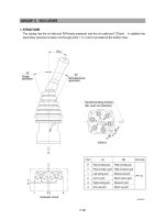
3. FUNCTION
CONTROL IN NEUTRAL POSITION
1)
XAtl
XAs
XAb2
XBtl
XBs
(PSP)
(XBp2)
103
S
SWING
B2
BOOM 2
A1
ARM 1
P1
TS
STRAIGHT
TRAVEL
TL
TRAVEL(L)
101
XBa1
XBp1
XAa1
21
22
13
4
XAtr
XAo
XAb1
XAa2
XBtr
XBo
XBb1
XAk
XBa2
TR
TRAVEL(R)
OP
OPTION
B1
BOOM 1
BK
BUCKET
A2
ARM 2
R2
P2
XBk
102
K
1
18
6
4
SECTION A-A
SECTION B-B
25072MC10
29072MC26
2-26
A2
XAa2
(XBp2)
611
611
BC
Dr2
LCa2
NR2
NR1
(XBp1)
(Ck1)
XBa2
F
L
F
R
4
13
13
4
A
B
J
A
P1
TL
TR
S
OP
B2
B1
A1
BK
BC
A2
P
Z
MR
TS
Dr2
NR2
R2(P2)
R1
Dr3
PaL
PbL
Dr4
Dr6
Pns
Px
PG
J
F
C
G
E
D
F
G
C
D
E
H
B
H
SECTION G-G
29072MC27
29072MC28
2-27
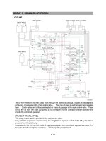
The hydraulic fluid from the pump P1 flows into casing A(101) through the inlet port(P1), through the
center bypass(21) and the parallel path(22). The hydraulic fluid from the pump P2 flows into casing
B(102) through the inlet port(P2) through the center bypass(18) and the parallel path(6).
The hydraulic fluid from the pump P1 is directed to the tank through the center bypass(21), negative
control orifice(NR1), the return path(13) and the return port(R2). The hydraulic fluid from the pump
P2 also flows to the tank through the center bypass(18), negative control orifice(NR2), return path
(4) and return port(R2). The hydraulic fluid in paths (6) and (22) is blocked and cannot return to the
tank.
In case a control lever is operated, the hydraulic fluid from the pump P2 is supplied to the travel right
spool(301) from path(18) and to the spools: option(309), boom1(303), bucket(304) and arm2(306)
from path(6). Additionally, the hydraulic fluid from the pump P1 is supplied to the travel left spool
(310) from path(7) while the swing(305), boom2(307) and arm(302) spools are supplied from
path(22).
2-28
NEGATIVE CONTROL
General operation
2)
(1)
303 18 21 3 4 5
10
7
611
19 6 27 28 22 13
9
611
Fl
Fr
P2 P1
The negative control signal pressure from the center bypass(18, 21) occurs in the following cases
and controls the discharge of the pump.
1. Neutral condition when no function is being actuated.
2. The pilot control lever is partially operated.
The hydraulic fluid of the pump P1(28) flows into the return passage(13) through the center bypass
(21), the path(3) and orifice(9)(Within the poppet(15)). The restriction caused by this orifice thereby
pressurizes path(3). This pressure is transferred as the negative control signal pressure Fl to the
pump P1 regulator through the negative control line(4). It controls the pump regulator so as to
decrease the discharge of the pump P1(28).
29072MC29
2-29
21
13
16
611
15
101
BC NR1
(XBp2)
Fl
Q
Qmax
Qmin
Fl1
Fl
QN
Fl
Fl1
The negative control relief valve(611) consists of poppet(15), spring(16) and casing(101). When
the hydraulic fluid in the center bypass increases to the level that the pressure in the path(3)
reaches the set pressure of the spring(16), the hydraulic fluid in the path(3) pushes open the poppet
(15) and escapes into the return path(13).
In the unloaded state, the hydraulic fluid of the pump P1(28) entirely flows to the tank through the
path(21), orifice(9) and the return path(13). Therefore the pressure Fl in the path(3) becomes
maximum(Fl1) because all the discharge is reduced by the orifice(9) which in turn destrokes the
pump P1(28) so as to minimize the tilting angle and consequent discharge of the pump P1(28).
(Qmin)
29072MC30
2-30
Negative control(With fine metering)
(2)
B1
XAb1
XBb1
Ab1
Bb1
LCb1
Ab1R
Bb1R
379
370
303
511
18 19
4
6
In the case, for example, when the pilot control lever for main boom is slightly operated, the pilot
pressure XAb1 shifts the main boom spool(303) partially in the left direction. So the path(19) is
partially opened and the center bypass(18) is shut slightly. The hydraulic fluid thereby separates.
One part flows via the orifice(7) through the path(18) and the other portion flows into the parallel
path(6), the path(19) and the port Ab1. The flow from the path(18) through the orifice(7) decreases
slightly and the pressure Fr in the path(10) thereby also slightly decreases. As the pressure Fr
becomes lower, the discharge of the pump P2(27) increases. With the pilot control lever shifted
even more the path(18) is shut off by the shifting of the spool(303) and then the flow through the
bypass becomes zero. The pressure in the path(10) becomes zero and the discharge of the pump
P2(27) becomes maximum.(Qmax)
Because the discharge of the pump is adjusted by operating the pilot control lever slightly, the
precise moving of the actuator is realized.
For the pump P1(28) the same negative control principle of operation occurs utilizing the orifice(9).
29072MC32