Máy đào HuynDai R250 - P2.3
Bạn đang xem bản rút gọn của tài liệu. Xem và tải ngay bản đầy đủ của tài liệu tại đây (685.41 KB, 16 trang )
2-47
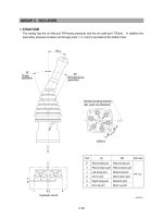
1. STRUCTURE
Swing device consists swing motor, swing reduction gear.
Swing motor include mechanical parking valve, relief valve, make up valve and time delay valve.
GROUP 3 SWING DEVICE
A
VIEW A
B
A
Pg
Sh
Dr(dr4)
Mu
Relief valve
Time delay valve
Swing motorReduction gear
R/G Air bleed port(AGr, PT 1/4)
R/G drain port(Dr, PT 3/8)
R/G grease fill port(SGr, PT 1/8)
Air bleed port
(Au, PF 1/4)
GB
GA
Port
A, B
Dr2
Mu
GA, GB
Pg
Sh
Port name
Main port
Drain port
Make up port
Gauge port
Brake release port
Brake pilot port
Port size
Ø19
PF 3/8
PF 1
PF 1/4
PF 1/4
PF 1/4
25072SM01
GB
Sh
Pg
Dr(dr4)
GA
AB
Mu
Au
25072SM02
2-48
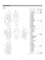
SWING MOTOR
1 Iner ring
2 Oil seal
3 Taper roller bearing
5 Backing spring
6 Cam plate
7 Return plate
8 Piston assembly
9 Lining plate
10 Plate
11 O-ring
12 Piston
13 O-ring
14 Spring
15 Parallel pin
16 Piston
17 O-ring
18 Cap
19 Scrowave
20 Teflon ring
21 Bushing
22 Balance plate
23 Needle bearing
24 Snap ring
25 Cylinder
26 Housing
27 Collar
28 Plug
29 Snap ring
30 Bypass valve assembly
31 Back up ring
32 O-ring
33 O-ring
34 Cover
35 Time delay valve
36 Hexagon socket bolt
37 O-ring
38 O-ring
39 Reliet valve assy
40 O-ring
41 Hexagon socket bolt
42 Check
43 Spring
44 Cap
45 Back up ring
1)
25072SM03
2-49
REDUCTION GEAR
1 Casing
2 Drive shaft
3 Spacer
4 Roller bearing
5 Cover plate
6 Hexagon bolt
7 Oil seal
8 Roller bearing
9 Carrier 2
10 Sun gear 2
11 Planet gear 2
12 Pin 2
13 bushing 2
14 Spring pin
15 Thrust washer
16 Carrier 1
17 Sun gear 1
18 Planet gear 1
19 Pin 1
20 Needle cage
21 Side plate 1
22 Ring gear
23 Knock pin
24 Socket bolt
25 Pinion gear
26 Lock plate
27 Lock washer
28 Hexagon bolt
29 Plug
30 Plug
31 Side plate 2
32 Stop ring
33 Spring pin
34 Spring pin
35 Gage bar
36 Gage pipe
2418
(B)
29
30
9
10
22
33
21 1920
36 35
31
32
17
3252627
1634
7
8
14
15
23
11 1213
1456
28
2
2)
25072SM04
2-50
2. FUNCTION
ROTARY PART
When high pressurized oil enters a cylinder through port(a), which is the inlet of balance plate(1),
hydraulic pressure acting on the piston causes axial force F. The pressure force F works via the
piston(2) upon the return plate(3) which acts upon the swash plate(4) via an hydrostatic bearing.
Force F1 perpendicular to swash plate(4) and force F2 perpendicular to cylinder center.
Being transferred to the cylinder block(5) through piston, force F2 causes rotational moment at
surroundings of cylinder.
Since cylinder block has 9 equidistantly arrayed pistons, rotational torque is transmitted to cylinder
shaft in order by several pistons connected to the inlet port of high pressurized oil. When the
direction of oil flow is reversed, rotational direction of cylinder is also reversed. Output torque is
given by the equation.
p×qF
T = , q=Z・A・PCD・tanθ, F1 = ,
F
2
=F tanθ, S=PCD×tanθ
2Л
COSθ
Where p : Effective difference of pressure(
kgf/cm
2
)
q : Displacement(
cc/rev
)
T : Output torque(
kgf・cm
)
Z : Piston number(9
EA
)
A : Piston area(
cm
2
)
θ: Tilting angle of swash plate(degree)
S : Piston stroke(
cm
)
1)
4 3 2 5 1
F
a
High
pressure oil
a
High
pressure oil
Low
pressure oil
F2
PCD
S
25072SM05
A
B
2-51
MAKE UP VALVE
In the system using this type of motor, there is no counter balance functioning valve and there
happens the case of revolution exceeding hydraulic supply of motor. To prevent the cavitation
caused by insufficient oil flow there is a make up valve to fill up the oil insufficiency.
A make up valve is provided immediately before the port leading to the hydraulic oil tank to secure
feed pressure required when the hydraulic motor makes a pumping action. The boost pressure
acts on the hydraulic motor's feed port via the make up valve.
Pressurized oil into the port B, the motor rotate counterclockwise.
If the plunger of MCV moves neutral position, the oil in the motor is drain via left relief valve, the
drain oil run into motor via right make up valve, which prevent the cavitation of motor.
2)
210LC-7(2-47)
2-52
1 Body
2 Seat
3 Plunger
4 Spring
5 Adjusting screw
6 Piston
7 Bushing
8 Spring seat
9 Shim
10 O-ring
11 Back up ring
12 O-ring
Construction of relief valve
The valve casing contains two cartridge type relief valves that stop the regular and reverse
rotations of the hydraulic motor. The relief valves relieve high pressure at start or at stop of swing
motion and can control the relief pressure in two steps, high and low, in order to insure smooth
operation.
Function of relief valve
Figure illustrates how the pressure acting
on the relief valve is related to its rising
process. Here is given the function,
referring to the figure following page.
5
6
9
3
11
10
7
8
12
1
4
2
RELIEF VALVE
3)
(1)
(2)
(210LC-7) 2-48(1)
P=pressure, T=time
P
P
S
P
1
P
2
1
2
3
4
T
(360LC-7) 2-51(1)