Máy đào Huyndai R480, 520LC - P4
Bạn đang xem bản rút gọn của tài liệu. Xem và tải ngay bản đầy đủ của tài liệu tại đây (497.49 KB, 10 trang )
3-123-12
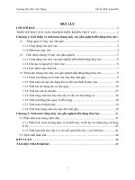
When the RH control lever is pulled back, the boom spools in the main control valve are moved to
the up position by the pilot oil pressure from the remote control valve.
The oil from the A1 and A2 pump flows into the main control valve and then goes to the large
chamber of boom cylinders.
At the same time, the oil from the small chamber of boom cylinders returns to the hydraulic oil tank
through the boom spool in the main control valve. When this happens, the boom goes up.
The excessive pressure in the boom cylinder bottom end circuit is prevented by relief valve.
When the boom is up and the control lever is returned to neutral position, the circuit for the holding
pressure at the bottom end of the boom cylinder is closed by the boom holding valve.
This prevents the hydraulic drift of boom cylinder.
1. BOOM UP OPERATION1. BOOM UP OPERATION
SWING MOTOR
TRAVEL MOTOR
FRONT
PUMP
REAR
PUMP
PILOT
PUMP
ARM
CYLINDER
BUCKET
CYLINDER
BOOM
CYLINDER
A1
A2
ps1
ps2
PSPS
T3
T1
T2
T4
pa10
B9
A9
pb9
pa9
B8
A8
pb8
pa8
pc2
A7
B7
pa7
pb7
B6
A6
pb6
pa6
P3
P2
PH
PA
PP
PT
P1
pr1
pa1
pb1
A1
B1
pc6
pa2
DR3
pb2
A2
B2
pa3
pb3
B3
A3
pa4
pb4
A4
B4
A5
B5
pc1
pa11
PS
pc2
pa3
pa11
pb9
pb5
PS
SH
HYDRAULIC TANK
Relief valve
Boom holding valve
STRAIGHT
TRAVEL
TRAVEL-LH
BOOM1
BUCKET
ARM2
ARM1
OPTION
TRAVEL-RH
BOOM2
SWING
DR2
pb3
DR1
PO
pb7
pa5
pci
pa9
pb3
GROUP 4 SINGLE OPERATIONGROUP 4 SINGLE OPERATION
48093HC10
3-133-13
When the RH control lever is pushed forward, the boom 1 spools in the main control valve are
moved to the down position by the pilot oil pressure from the remote control valve.
The oil from the A2 pump flows into the main control valve and then goes to the small chamber of
boom cylinders. At the same time, the oil from the large chamber of boom cylinders returns to the
hydraulic tank through the boom 1 spool in the main control valve.
When the down speed of boom is faster, the oil returned from the large chamber of boom cylinder
combines with the oil from the A2 pump, and flows into the small chamber of the boom cylinder.
This prevents cylinder cavitation by the negative pressure when the A2 pump flow can not match the
boom down speed. And the excessive pressure in the boom cylinder rod end circuit is prevented by
the relief valve.
2. BOOM DOWN OPERATION2. BOOM DOWN OPERATION
BOOM1
SWING MOTOR
TRAVEL MOTOR
FRONT
PUMP
REAR
PUMP
PILOT
PUMP
ARM
CYLINDER
BUCKET
CYLINDER
BOOM
CYLINDER
A1
A2
ps1
ps2
PSPS
T3
T1
T2
T4
pa10
B9
A9
B8
A8
pb8
pa8
pc2
A7
B7
pa7
pb7
B6
A6
pb6
pa6
P3
P2
PH
PA
PP
PT
P1
pr1
pa1
pb1
A1
B1
pc6
pa2
DR3
pb2
A2
B2
pa3
pb3
B3
A3
pa4
pb4
A4
B4
A5
B5
pa11
PS
pa3
pa11
PS
SH
HYDRAULIC TANK
Relief valve
Boom holding valve
STRAIGHT
TRAVEL
TRAVEL-LH
BUCKET
ARM2
ARM1
OPTION
TRAVEL-RH
BOOM2
SWING
DR2
DR1
PO
pb7
pb3
pb9
pa9
pb7
pc1
pc2
pb9
pb5
pa5
pci
pa9
pb3
48093HC11
3-143-14
When the LH control lever is pulled back, the arm spools in the main control valve are moved the to
roll in position by the pilot oil pressure from the remote control valve.
The oil from the A1 and A2 pump flows into the main control valve and then goes to the large
chamber of arm cylinder.
At the same time, the oil from small chamber of arm cylinder returns to the hydraulic oil tank through
the arm spool in the main control valve. When this happens, the arm rolls in.
The excessive pressure in the arm cylinder head side is prevented by relief valve.
The cavitation which will happen to the head side of the arm cylinder is also prevented by the make-
up valve in the main control valve.
3. ARM IN OPERATION3. ARM IN OPERATION
SWING MOTOR
TRAVEL MOTOR
ARM
CYLINDER
BUCKET
CYLINDER
BOOM
CYLINDER
ps1
ps2
PSPS
T3
T1
T2
T4
pa10
B9
A9
B8
A8
pb8
pa8
pc2
A7
B7
pa7
pb7
B6
A6
pb6
pa6
P2
PH
PA
PP
PT
P1
pr1
pa1
pb1
A1
B1
pc6
pa2
DR3
pb2
A2
B2
pa3
pb3
B3
A3
pa4
pb4
A4
B4
A5
B5
pa11
PS
pa3
pa11
PS
SH
STRAIGHT
TRAVEL
TRAVEL-LH
BOOM1
BUCKET
ARM2
ARM1
OPTION
TRAVEL-RH
BOOM2
SWING
FRONT
PUMP
REAR
PUMP
PILOT
PUMP
A1
A2
HYDRAULIC TANK
Relief valve
Arm holding valve
DR2
P3
pb3
DR1
PO
pb7
pb9
pa9
pc1
pc2
pb9
pb5
pa5
pci
pa9
pb3
48093HC12
3-153-15
When the LH control lever is pushed forward, the arm spools in the main control valve are moved to
the roll out position by the pilot oil pressure from the remote control valve.
The oil from the A1 and A2 pump flows into the main control valve and then goes to the small
chamber of arm cylinder.
At the same time, the oil from the large chamber of arm cylinder returns to the hydraulic oil tank
through the arm spools in the main control valve. When this happens, the arm rolls out.
The excessive pressure in the arm cylinder rod side is prevented by relief valve.
When the arm is roll out and the control lever is returned to neutral position, the circuit for the holding
pressure at the rod side of the arm cylinder is closed by the arm holding valve.
The cavitation which will happen to the rod side of the arm cylinder is also prevented by the make-up
valve in the main control valve.
4. ARM OUT OPERATION4. ARM OUT OPERATION
pb7
Relief valve
SWING MOTOR
TRAVEL MOTOR
ARM
CYLINDER
BUCKET
CYLINDER
BOOM
CYLINDER
ps1
ps2
PSPS
T3
T1
T2
T4
pa10
B9
A9
B8
A8
pb8
pa8
pc2
A7
B7
pa7
B6
A6
pb6
pa6
P2
PH
PA
PP
PT
P1
pr1
pa1
pb1
A1
B1
pc6
pa2
DR3
pb2
A2
B2
pa3
pb3
B3
A3
pa4
pb4
A4
B4
A5
B5
pa11
PS
pa3
pa11
PS
SH
STRAIGHT
TRAVEL
TRAVEL-LH
BOOM1
BUCKET
ARM2
ARM1
OPTION
TRAVEL-RH
BOOM2
SWING
FRONT
PUMP
REAR
PUMP
PILOT
PUMP
A1
A2
HYDRAULIC TANK
Arm holding valve
DR2
P3
pb3
DR1
PO
pb7
pb9
pa9
pc1
pc2
pb9
pb5
pa5
pci
pa9
pb3
48093HC13
3-163-16
When the RH control lever is pulled left, the bucket spool in the main control valve is moved to the roll
in position by the pilot oil pressure from the remote control valve.
The oil from the A2 pump flows into the main control valve and then goes to the large chamber of
bucket cylinder. The oil form the A1 pump flows into the large chamber of bucket cylinder through
confluence oil passage in the main control valve by bypass cut pilot pressure (pa11).
At the same time, the oil from the small chamber of bucket cylinder returns to the hydraulic oil tank
through the boom spool in the main control valve. When this happens, the bucket rolls in.
The excessive pressure in the bucket cylinder head side is prevented by relief valve.
The cavitation which will happen to the head side of the bucket cylinder is also prevented by the
make-up valve in the main control valve.
5. BUCKET IN OPERATION5. BUCKET IN OPERATION
BUCKET
SWING MOTOR
TRAVEL MOTOR
ARM
CYLINDER
BUCKET
CYLINDER
BOOM
CYLINDER
ps1
ps2
PSPS
T3
T1
T2
T4
pa10
B9
A9
B8
A8
pb8
pa8
pc2
A7
B7
pa7
pb7
B6
A6
pb6
pa6
P2
PH
PA
PP
PT
P1
pr1
pa1
pb1
A1
B1
pc6
pa2
DR3
pb2
A2
B2
pa3
pb3
B3
A3
pa4
pb4
A4
B4
A5
B5
pa11
PS
pa3
pa11
PS
SH
STRAIGHT
TRAVEL
TRAVEL-LH
BOOM1
ARM2
ARM1
OPTION
TRAVEL-RH
BOOM2
SWING
FRONT
PUMP
REAR
PUMP
PILOT
PUMP
A1
A2
HYDRAULIC TANK
Relief valve
DR2
P3
pb3
DR1
PO
pb7
pb9
pa9
pc1
pc2
pb9
pb5
pa5
pci
pa9
pb3
48093HC14