LightWave 3D 8 1001 Tips & Tricks phần 3 potx
Bạn đang xem bản rút gọn của tài liệu. Xem và tải ngay bản đầy đủ của tài liệu tại đây (1.45 MB, 65 trang )
mode, and click on the + next to 1 Vertex and 2 Vertices to select them all.
Delete them, and save the model with a different name for export.
Versions: 6.5-8
260
Robin Wood | Import/Export | Beginner to Intermediate
Preparing Files for Export — Exporting UV Maps
If you want to export a model to another format, such as .obj, with the UVs
intact, simply use the map in at least one channel in each material, and export.
The UVs will be retained. (You don’t even have to assign an image, just the
UVs.)
Versions: 6.5-8
261
Patrik Beck, Robin Wood | Import/Export | All Levels
Loading DFX, OBJ… and 3DS Files?
LightWave can load several different object formats, such as .dxf, .obj, and
.3ds, even though the option is semi-hidden. Select Load Object as you normally
would, navigate to the directory containing the non-LightWave object, and select
the All Files option so that files with extensions other than .lwo will show up.
This allows you to load public domain objects you find on the Internet or object
collections that may not be in the native LightWave .lwo format.
Versions: All
ð
Mac Note (Robin Wood): On the Mac, changing Show to All Documents enables the other formats
so you can select them. (When LightWave objects are showing, you can see them, but they are dimmed.) It’s
possible that the names will still appear to be dimmed. Go ahead and click anyway; they will open.
262
Brad Krause | Import/Export | Intermediate
Export Orthographic Views
You can export any of the three orthographic views or all three of them at
once out of Modeler using the EPSF exporter. You can also export the object’s
wireframe in a UV map view after you create a UV map.
These exported views can be best used for placement into Adobe Illustrator
or any other vector or bitmap program to create a quickie CAD-like drawing.
Versions: 5-8
Ü
Note: Only objects in a single foreground layer will be exported.
102 | Chapter 3
Import/Export
Chapter 4
Modeling
It can be argued that learning to model is the single greatest challenge facing
new users. While primitives are fun and give you immediate gratification, there
comes a point when the novelty of making balls, boxes, and cones wears off and
the need to actually make something settles in. When this happens, most users
hit a very steep wall. Certainly they expect some type of learning curve. But
most aren’t prepared for the “insurmountable” wall that looms before them. As
the weeks go by and they find themselves still climbing that wall, their enthusi
-
asm often wanes. You see, learning to model is not synonymous with learning
Modeler. It is a skill that requires time and dedication and is no different than
learning to paint, sculpt, or draw. Taken in this light, it’s easy to understand why
modeling presents such a formidable challenge to new users. Still, for those who
stick with it, modeling can be incredibly rewarding. The ability to realize your
dreams in 3D is exhilarating. And the freedom that comes from knowing you
can model anything you desire is simply intoxicating.
Still, modeling can present challenges to even the most experienced artists.
Experience often yields confidence; however, confidence should never be mis-
taken for expertise. The skills needed to model photorealistic cars and planes are
completely different from those needed to model realistic human beings. Having
experience in one area does not make you adept in all areas, and even the most
talented artist will struggle when working outside of his comfort zone.
The bottom line is that we all need a little help now and then. And this chap
-
ter provides it in droves. For new users, these tips can make the wall look more
like a curve. For experienced users, they can help get the job done faster.
Whether you’re just beginning your climb up the wall or you’ve been modeling
like a pro for years, the tips in this chapter will meet you where you’re at and
provide a valuable resource for years to come.
— Steve Warner
General Tips
263 Steve Warner | General Tips | Beginner
Point Info Window
You can use Modeler’s Point Info window (“i” keyboard shortcut) to interac
-
tively adjust the position of selected points in your object. In this regard, the
Point Info window functions like an interactive version of the Set Value tool.
But it can be used for much more than setting global point positions. If you’ve
103
ever dealt with two or more points that overlap but are not welded, you know
that moving one but not the other can be difficult. With the Point Info tool, how
-
ever, you can select just the point you want to move and adjust its x, y, and z
coordinates.
Versions: 6-8
264
Robin Wood | General Tips | All Levels
Don’t Overlook Point Info
Don’t overlook the Point Info panel. Just select the points you want to work
with, and tap “i” on your keyboard to bring it up. From here, you can examine or
edit anything you like about all of those points or any number of them, including
their position in x, y, z space and the attributes they hold in any vertex map they
are part of (color and alpha for color maps, U or V value for UV maps, etc.).
You can also examine but not change other information, such as the number of
polys that share that point.
When you open the panel, each selected point will be labeled in the
viewports, so it’s easy to see exactly which ones you are working with.
There’s similar information for polys, too. Just select them and tap “i” to
find out their type, how many points they have, and their flatness, surface, and
wireframe colors.
These two panels are perfect places to check when you suspect that you have
multiple points or polys and can’t select them individually (you can, once you’re
in here) or when you need to change the values of a raft of points simultaneously
or set values for several axes at once, or do other examinations and modifica-
tions (especially now that the dynamics will read all the VMaps). This is the one
place where you can easily find out which points are used in which maps and
what their values are!
Versions: 6.5-8
265
William “Proton” Vaughan, Wes “kurv” Beckwith | General Tips | All Levels
Black Wireframe Shade
If you would like to see your object with black wireframe shade, simply
copy the object into another layer and put it in the background with your original
object in the foreground. There you have it — black wireframe shade.
Alternatively, LightWave 8 has added texture wireframe mode in which you
can make your wireframes any color. To do this, simply change the sketch color
in the Detail tab. Remember, if nothing is selected in LightWave that is the same
as everything being selected. Having said that you can also select specific polys
on which to change the wireframe colors.
Versions: All
104 | Chapter 4
General Tips
266 Timothy “Amadhi” Albee | General Tips | All Levels
Easy on Your Wrist
Using a Wacom or other digitizing tablet when you’re dragging points is
much easier on the wrist than using a mouse — “tap-and-drag” vs.
“click-hold-drag-release.”
Versions: All
Scanning and Setup
267 Jennifer Hachigian | Scanning and Setup | Beginner
Cel-shaded Modeling
When modeling a cel-shaded model, use an actual drawing as your model
sheet instead of referencing a photograph or trying to model without reference.
Scan the drawing, load it in as a backdrop image, and try to match the contours
and proportions of the drawing with your model. Leave out the details that the
drawing leaves out. For example, if the model sheet does not depict nostrils for
the character, do not model nostrils. Otherwise, the character model will not
match the drawing. LightWave’s Edges and Super Cel Shader cannot add or
remove detail to a model; they can only trace existing polygonal edges and sim-
plify the shading. This is why loading up a photorealistic humanoid model and
slapping edges and a cel shader onto it does not often deliver the look of a genu-
inely good drawing.
Versions: 6-7.5
268
Wes “kurv” Beckwith | Scanning and Setup | All Levels
Using Backdrops
Be sure to save your work when creating backdrops. On the Display Options
panel’s Backdrop tab, click on Presets and choose Save All Backdrops to create
a file containing all of your current backdrop information. You can also choose
Save Current Backdrop to save only the current backdrop you are working on,
either the TL (Top Left), TR (Top Right), BL (Bottom Left), or BR (Bottom
Right). Be careful not to choose Save Current Backdrop when you intend to save
all backdrops.
Versions: 5-8
Ü
Note: This is important because when you save your file LightWave does not save the backdrops with
it. If you are like me you may have done this once or twice and wanted to shoot someone…
Modeling | 105
Scanning and Setup
269 William “Proton” Vaughan | Scanning and Setup | All Levels
Using Reference Images
When modeling something with reference images, I have found that it helps
to use the Sketch tool to trace the image. This way I end up with a 3D sketch
that I can use in the Background layer and have it show up in the Perspective
view.
Versions: All
270
William “Proton” Vaughan | Scanning and Setup | All Levels
EPS Importer
Don’t forget the power of the EPS importer for use with reference images. If
you have clean black and white reference images, you can always use
Photoshop, Illustrator, or Flash — my favorite — to auto trace the image and
save it out as an EPS or Illustrator file. These files are great for background tem
-
plates to model from.
Versions: 6-8
271
William “Proton” Vaughan | Scanning and Setup | All Levels
Mapping an Image on a Polygon
If you would like your reference image to show up in the Perspective win-
dow, simply map the image to a flat polygon. In Texture view mode, the image
will show up in the Perspective view.
Versions: All
272
William “Proton” Vaughan | Scanning and Setup | All Levels
Breasts and Butts
At some point you’re probably going to want to model a woman. Here is a
tip I wish I had known when creating my first few female models. When you
want to model areas that need to be smooth and round, like a butt or breast,
place a ball object in the background layer to use as a guide. This has saved me
several times when creating character models, but is not limited to butts and
breasts. (I just love to type those words whenever I can. :))
Versions: All
Object Construction
273 Jonny Gorden | Object Construction | Beginner
Model to Scale
Where possible, make your objects to scale. This way when you are setting
them up in scenes you don’t have to do any rescaling.
Versions: 6-8
106 | Chapter 4
Object Construction
274 Timothy “Amadhi” Albee | Object Construction | All Levels
Work Smart, Not Hard
If something is only going to be seen in silhouette, only model its silhouette.
Versions: All
275
Wes “kurv” Beckwith, Robin Wood | Object Construction | All Levels
Easy Undo
I found this by accident. I was modeling a head and went to perform a
Smooth Shift to start making the eyes. I thought I had pressed the Spacebar to
drop the Smooth Shift tool and clicked in the gray area, and it undid my Smooth
Shift. I have tried this on several tools and it works by resetting each tool to its
original state, simulating an undo. So if you want to quickly undo the last modi
-
fication to your object, try clicking on the gray area instead of using Ctrl+z.
Test it for yourself….
Versions: 5-8
Ü
Note: This does not work with the Modify tools.
276
Kevin Phillips | Object Construction | Beginner
Work Flow — Colorful Wireframe Welding
I was modeling a WWII aircraft in which I was joining the wings onto the
fuselage of the model. What was difficult was that in wireframe mode, things
got quite confusing — to say the least! The same color wireframe for both fuse-
lage and wing, lines and points everywhere — surely there was an easier way.
Luckily, I was able to make my life a little easier by selecting all the wing
polygons, then selecting the Detail>Sketch Color option and setting my wing
sketch color to be red, rather then the default gray. Once I had the different color
applied, I switched the viewport to Color Wireframe. Now that I could see each
part in a different color, it made selecting the right points a lot easier!
Versions: 7.5-7.5c
277
Robin Wood | Object Construction | Beginner to Intermediate
Speed Screen Redraw
If you don’t need to see your model in SubPatch mode, you can speed up
screen redraw considerably by tapping the Tab key to return your model to
Faces.
If only part of the model is using SubPatches, you can assign all the polys
you want to be SubPatched to a part using the Create Part button (in LightWave
7.x: Display>Selection>Grouping>Change Part Name…). That will let you
select them easily (from the Polygon Statistics>Part: menu) when you are ready
to toggle them back. (The only caveat is that you cannot assign polys to more
than one part. So, if you’re using parts for something else, you may not want to
do this.)
Versions: 6.5-8
Modeling | 107
Object Construction
278 Steve Warner, Kevin Phillips | Object Construction | Beginner
Work Flow — Hide Selected and Unselected
If you are working on complex meshes where hunting for that elusive point,
edge, or poly gets difficult, or Modeler starts to become sluggish, select all the
non-necessary polys and press the – key to hide them and make your life a little
easier! (Alternatively, pressing the = key will hide the non-selected polys.)
Once you’re done, pressing the backslash key (\) will unhide the polys.
This will also help you isolate the area you’re working on, which can be
extremely helpful when working in the orthographic views in version 7.5 or ear
-
lier (as they lack LightWave 8.0’s new Hidden Line view mode).
Holding down the Shift key while pressing the backslash will toggle
between hidden and unhidden. Thanks to Robin Wood for making me aware of
this keyboard tip!
Versions: 6-8
279
Robin Wood | Object Construction | Beginner to Intermediate
Save Ephemera for Later Adjustment
Sometimes while you’re working you’ll wish that you could go back and
adjust a Boolean, lathe, extraction, etc., without losing the work you’ve done on
the other parts of the model since. To make it easy to do that, save all those bits
in a “working” file.
Just open a new file, append “working” to the name, and copy and paste all
Booleans, outlines, curves, and other ephemera into it. Save as soon as it’s
pasted, so you won’t lose anything. Then, if you need them at any time (even
weeks or months later), you’ll still have all those parts and won’t have to recre-
ate them.
Versions: 6.5-8
280
Robin Wood | Object Construction | Beginner to Intermediate
The Measure Tools Are Your Friends
Don’t be afraid to use the Measure tools and do a little arithmetic. They can
save you tons of time.
Measure, Angle, and PointCenter are found under Detail>Measure (or Con
-
struct>Utility in LightWave 7.x). (If you’re on a PC or using LW 8, you may
have others as well, including Find Center and Bounding Box.) Measure and
Angle give you a positionable blue line while showing the length or angle in the
Info Display. PointCenter gives you the coordinates of the average of all
selected points (or all visible points, if none are selected). Find Center puts a
new point in the center of a selected poly, and Bounding Box gives you the coor
-
dinates of a bounding box that encloses everything on the layer (and also
replaces it all with a simple box if you click OK, so be careful).
108 | Chapter 4
Object Construction
Using them, you can determine the measurements for clones and arrays, the
correct angles of a gemstone to get the best internal reflections for the refraction
index, the exact spot to use for the center of a radial array, and many, many more
things.
Versions: 6.5-8
281
Robin Wood | Object Construction | All Levels
A Little Math Can Save a Lot of Time
A little bit of math can often save a lot of time. Not just simple arithmetic,
like figuring out angles of rotation, etc., but actual equations.
If you don’t know the equation for something, sometimes it’s faster to look it
up on the web than to try to find the correct numbers through trial and error.
For instance, use the Pythagorean equation (a
2
+b
2
=c
2
) to find the cloning
settings for a row of balls with a radius of1msothey’ll line up like unbroken
pool balls (1 m on the x-axis, and 1.732 on the z). Use it again to find the set
-
tings to stack those spheres like cannon balls (x=1, y=1.633, z=.5774, then
delete the ones you don’t need). Use C=pD to find out how far a wheel with a
diameter of 1 m should travel for each complete rotation (3.14159 m). And
that’s just a few of the useful equations! Remember, calculators and the Numeric
Requester are your friends.
Versions: 6.5-8
Layers
282 William “Proton” Vaughan | Layers | All Levels
Layer Names
You set up layer names in Modeler, but they really help you in Layout.
Maybe this is why many people forget to use them. When using a multilayered
object you can name each layer easily in the Layer panel.
Which do you like better when animating:
1. Robot: Layer1 (unnamed layer)
2. Robot: Left Arm (named layer)
Simply double-click on the name (default name is Unnamed) in the Layer
panel (Ctrl+F5). This really comes in handy when you are trying to find a partic
-
ular object in a scene and you can’t remember what layer the robot’s arm is in.
In a simple scene this might not be so important, but in a complex scene full of
objects this becomes very important.
Also, while you have the Layer panel open to name your layer, you could
parent the layer as well, which will save you time in Layout.
Versions: All
Modeling | 109
Layers
283 William “Proton” Vaughan | Layers | All Levels
The Power of Layers
When modeling, I find it very useful to copy my work into the next available
layer every few minutes to save a backup of my work. By doing this I never run
out of undos and I save my steps along the way. It’s also very useful to pull one
of these steps (layers) for use with a new model that has similar geometry.
For example, a head model pulled in an early stage can easily be modeled
into a completely new model, thus saving hours of work in some cases.
Versions: All
284
Timothy “Amadhi” Albee | Layers | All Levels
Swapping Layers
If you’re working in a particular layer and want to put that layer into the
background, and bring another, currently unselected layer into the foreground,
the quickest way to do this is to put the layer you’d like to have as your fore
-
ground into the background, and then press the ’ (apostrophe) key, which will
swap your foreground and background layers.
Versions: All
285
William “Proton” Vaughan | Layers | All Levels
Layer Merge
Here’s a quick way to take a multilayered object and collapse it into one
layer. With all layers in the foreground, cut (Ctrl+x) all layers. Select the first
layer and paste (Ctrl+v) the objects in the layer. There you go.
Versions: All
Ü
Note: Object Collapse in LightWave 8 does this in one step.
286
Steve Warner | Layers | Beginner
Layers in LW 8
Modeler 8 includes some nice new layer tools (which can be found in the
View tab), including the ability to merge layers or collapse them into a new
object. But what if you want to redistribute parts of your object after you’ve col
-
lapsed it? Do yourself a favor and surf on over to />~fisjunk/plugin/plugin.php to pick up a copy of Fi’s CrackIt Pack. It includes
three plug-ins: CrackIt, Merge High Layers, and Distribute (each of which is
cross-platform compatible). The real gem in this plug-in set is the Distribute
tool. It will take any polys that do not share points (in other words, distinct
objects whose points are not welded together) and place them on separate layers.
Let’s say you have a character. The hair, shoes, shirt, and pants are all separate
objects from the body. By using the Distribute tool, you can place each of these
objects on separate layers for easy editing. Then use either Merge High Layers
or Modeler 8’s new layer tools to rejoin them.
Versions: 6-8
110 | Chapter 4
Layers
287 William “Proton” Vaughan | Layers | All Levels
Locking Layers
Using the Layers panel allows you to lock layers (just click in the eyeball
column). Locking layers appears to do nothing in Modeler but it will stop those
layers from loading objects into Layout. I like to leave my Boolean objects (the
cutting objects) in my model but lock them off so they won’t load into Layout.
This can be very useful for storing unwanted geometry for Layout in the model.
Versions: 6-8
Selection
288 Larry Shultz | Selection | Beginner
Basic Selecting and Deselecting
LightWave Modeler supports two types of basic primitives or elements —
points and polygons. In order to be able to create a model, it is important to
know how to select and deselect those elements. At the bottom left of the Mod-
eler screen you will see a button labeled Point and another labeled Polygons. It
is important to be in the proper “mode” to select points or polygons.
In point mode you can select a single point by putting the cursor or mouse
pointer over the point and clicking the left mouse button. This will select a point.
If you keep the button depressed and don’t let go, you can move the cursor over
other points and continue selecting more points. If for some reason you let go of
the left mouse button, you can continue selecting by holding down the Shift key
and using the left mouse button as usual. This works the same way for points or
polygons.
There are three ways to deselect. Simply let go of the left mouse button and
click on a selected point or polygon and it will deselect it. Click the left mouse
button anywhere in a blank spot in the gray border surrounding the active
viewport or press the / (forward slash) key to deselect all the selected points and
polys.
Group select points or polygons by clicking the right mouse button and hold
-
ing it down, then draw a blue line around or lasso what is needed. Deselect the
same way described above or lasso deselect with the right mouse button.
Versions: 5-8
289
Timothy “Amadhi” Albee, Steve Warner, Wes “kurv” Beckwith | Selection | All Levels
Selecting and Deselecting
Modeler’s tools work only on the points/polys you have selected. You can
isolate sections of your model by selecting them; tools such as Drag will ignore
all but the selected points/polys/patches. Remember that if nothing is selected,
Modeler often assumes everything is selected.
Versions: All
Modeling | 111
Selection
290 Dave Jerrard, Rob Powers | Selection | Beginner
Always Select
In Modeler, the middle mouse button acts as an “always select” tool.
Normally, you use the left button to select points or polygons. As long as you
don’t release the button, it will continue to select them as you drag the mouse
around, but once you let go, you need to use the Shift key to continue selecting
or the cursor will start deselecting. By alternating between the left and middle
mouse buttons you can select and deselect without ever having to touch the
keyboard.
Versions: 7-8
291
Robin Wood | Selection | Beginner
Selecting the End Caps
When you make certain primitives, for instance the disk (which makes a
cylinder), you may find that you want to select the end caps for one reason or
another. Assuming that you’re working with the Polygon Statistics window open
(which I highly recommend), you can select them both with a single click by
clicking the + next to “>4 Vertices.” That will select all the polygons that have
more than four points, which in this case means the end caps.
The Statistics window, in fact, is a great way to select all kinds of things,
which is why it’s handy to have it there at all times. You can select by surface,
part, type, number of vertices, wireframe color — all kinds of ways.
Versions: 6.5-8
292
Robin Wood | Selection | Beginner to Intermediate
Select Polys by Normal
If you want to select polys that have their normals visible from only one
axis, change to one of the shaded modes in the appropriate viewport, and use the
lasso (right mouse button). Only the visible polys will be selected. (You may
need to do this in several steps, depending on the shape of your object.)
Versions: 6.5-8
293
Steve Warner | Selection | Beginner
Quickly Reselect
In Modeler, if you have made a fairly complex selection of points or polys,
then made a modification to it and deselected, only to realize you needed to keep
the selection for further modification, simply undo and then redo. This will bring
you back to the place you were before deselecting.
Versions: 6-8
294
Robin Wood | Selection | Beginner
Select Objects from Tightly Packed Groups
If you want to select a number of complete objects from a closely packed
group, all you have to do is draw a lasso with the right mouse button that catches
112 | Chapter 4
Selection
some polys from each object, and then press the ] key (right bracket) to select all
the polys in that object.
Versions: 6.5-8
295
Steve Warner | Selection | Beginner
Making Complex Selections with
Expand and Contract Selection
The expand and contract selec
-
tions (} and {, respectively) are
terrific ways to select points and
polys in hard-to-reach areas, such as
the innermost edge loop of a charac
-
ter’s eyelid. Simply select the polys
close to the area you want selected,
then choose to expand or contract the
selection. Oftentimes by using a
combination of these (for example,
expanding several times to include
all the polys you want, then contract-
ing to limit the range) you can get
just the polys you want selected
without having to hide entire parts of
your object.
Versions: 6-8
296
Leigh van der Byl, William “Proton” Vaughan,
Eki Halkka | Selection | All Levels
Selecting Polygons by Their Surfaces
This may sound like a bit of a
stupid tip, but I actually find myself
using it often. If you have a single
model that has a number of different
surfaces assigned to it, you might
find yourself wanting to select poly
-
gons according to the surface that is
assigned to them, without having to
painstakingly select each polygon
one by one.
To select polygons by their sur
-
faces, simply open up the Polygon
Statistics window by pressing “w”
when in Polygon mode (Ctrl+h).
Modeling | 113
Selection
The third item from the bottom of the panel is Surf. Clicking on the little
arrow to the right of the Surf label brings up a list of all the surfaces that are
assigned to the model currently displayed in your viewports.
Select a surface from the list. The name of the surface then appears next to
the Surf label. Clicking on the little + symbol to the left of the Surf label then
selects all the polygons to which that particular surface is applied.
Versions: 6.5-8
114 | Chapter 4
Selection
297 William “Proton” Vaughan | Selection | All Levels
BandSaw Tool for Selection
Besides being a great tool for cutting geometry, BandSaw is great for select
-
ing bands (loops). Select a few polygons in the loop and run BandSaw. Make
sure Enable Divide is unchecked and click OK. BandSaw will select the loop
without performing any cut.
Versions: All
Ü
Note: Select Loop in LightWave 8 does the same thing but only if the selected polys are adjacent.
(BandSaw doesn’t care.)
298
Leigh van der Byl | Selection | Intermediate
Using Parts
Parts in Modeler are one of those funny little features that nobody ever men
-
tions. Basically they are groups of polygons (selections) that you can save for
easy reselection at a later stage. I use parts a lot, especially when setting up
things like morph targets in Modeler, where I often find myself having to
reselect areas such as the jaw of a character or the brows or the entire mouth,
etc. Having to reselect all the polygons in a certain area every time you want to
adjust it again is a real pain. This is where the Parts feature comes in handy.
Let’s look at an example. I have a character’s head that I am making morph
targets with. With each of the morphs, I need to move the lower jaw around.
Obviously, having to constantly reselect that entire area every time I want to
move it to a new position is going to make me very irritable.
However, I can save this selection as a part, so that I can
reselect it at the touch of a button later on. To save this selection
as a part, go to the View tab in Modeler and click on the Create
Part button under the Selection Sets heading.
Modeling | 115
Selection
A window pops up into which I can enter a name for the part. For this partic
-
ular instance I simply use the name “lower jaw.” Now, at a later stage when I
want to select those polygons, all I need to do is hit “w” when in Polygon mode
(Ctrl+h) to bring up the Polygon Statistics panel. Second from the bottom in this
panel is the Part label. Clicking on the little triangle to the right of the label
gives me a list of all the parts I have assigned to the model that is visible in my
viewports.
I can then select that part and hit the little + symbol to the left of the Part
label in the Polygon Statistics window to actually select that part.
Versions: 6.5-8
299
Robin Wood | Selection | All Levels
Putting Polys in More than One Part
Ever wish you could have polys in more than one part? Well, you can’t do
that, of course, but in LightWave 8 you can get the same result by using one of
the new Selection tools and the well-known ability to have points in multiple
selection sets.
Just select the polys you want for a part, and then use Sel Switch (View>
Selection: More) to choose the points that are connected to those polys. Make a
selection set using either the VMap bar or the Selection Sets button (View>
Selection Sets: Selection Sets). Do this for each extra part you want.
When you want to use them, simply reverse the process. Click the + in the
Point Statistics panel for the selection set, and then Sel Switch to change to the
polys for those points. And there you are — all the polys neatly selected and
ready to go, with the very same poly in as many sets as you like.
Version: 8
300
Jennifer Hachigian | Selection | Intermediate
Grouping by Color
In addition to grouping polygons by surface and part names, you have a third
grouping option for polygons — Polygon Color. The fastest way to color
116 | Chapter 4
Selection
polygons is to use Change Sketch Color (Detail>Polygons>Change Sketch
Color). This tool works on selected polygons/volumes. If no geometry is
selected, it will color all of the polygons at once.
Another way to color the polygons is to select the polygons that you want to
color, press “i” to bring up the Info panel for those polygons (Display>Selec
-
tion>Info), then select the color that you want for those polygons from the Color
drop-down list. Once you have added color to your polygons, you can then
reselect those polygons from the Polygon Statistics panel in the Color section.
In LightWave 8, the button for the Info panel is found at the bottom of the
Modeler interface.
Versions: 7-7.5
301
Steve Warner | Selection | Beginner
Volume Select
The Volume Select tool is the ugly duckling of Modeler’s selection toolset.
But it shouldn’t be. This is LightWave’s equivalent to the Lasso and Rectangular
Marquee tools in Photoshop. Learning to use it and implementing it into your
work flow can save you valuable time. The Volume Select tool does not require
you to directly select points or polys, but it still allows you to restrict your
actions to a defined region of your object. This can be very helpful when you
want to operate on a highly complex object and find that the Points and Polys
lasso tools are too sluggish or that they aren’t catching every part of the object
you want to operate on. The Volume Select tool is also helpful when editing
SubPatch objects, as it will enable you to restrict your modification to a specific
area (i.e., the eyes or the mouth) but it won’t inhibit the view of your model in
Smooth Shaded or Texture Shaded view types.
Versions: 6-8
302
Steve Warner | Selection | Beginner
Volume Select Modes
If you right-click when using the Volume Select tool in Modeler, you can
drag out an irregular shaped selection area. This works with both the Include and
Exclude modes. In LightWave 8, the Volume Select modes have been removed
from the interface, but they can still be accessed via the Ctrl+j keyboard shortcut
(hit once for Exclude and twice for Include).
Versions: 6-8
303
Robin Wood | Selection | Beginner to Intermediate
Find the Center of Any Selection on the Fly
It’s easy to automatically load the center of a selection into the Numerical
Requester so you can perform precise operations on an object. To do so, make
sure the Numerical Requester is open, set the mode to Action Center: Selection,
and perform any interactive operation.
When you do, the numbers in Center X, Y, Z fields will change to show that
center. Undo the action, and the numbers will persist. Now, just enter the
Modeling | 117
Selection
numbers you need into the Angle, Size, or whatever fields. The operation will
occur around the center of the selection.
Versions: 6.5-8
304
Robin Wood | Selection | Beginner
See Your Model Selection-Free Without Losing It
You can toggle back and forth between points and polys without losing your
selection in either one. This means that if you are working with polys selected
and you want to see what the model looks like without the distracting yellow
lines, all you have to do is tap the Spacebar to toggle to Point selection. The
lines vanish. Take a good look, then tap again. (Tap three times in 7.x to go
through the Volume settings.) Your poly selection is intact, waiting for you to
resume work.
Versions: 6.5-8
Copy/Paste
305 William “Proton” Vaughan | Copy/Paste | All Levels
Special Paste Method
Here’s a simple technique for pasting geometry to ensure that it lines up with
existing geometry:
1. Select the geometry that you want to copy.
2. Move the geometry to the new location.
3. Select Copy.
4. Select Undo to move the geometry back to its original position.
5. Select Paste (7.5) or Paste in Place (8).
Versions: 7.5-8
Ü
Note: This will paste the new geometry where the original geometry was placed before the undo and
at the time it was copied. This method will allow you to copy/paste without moving the original points
(which are sometimes attached to other geometry). When you select something, then copy and paste, the
original item remains selected. So if you move it, you’re moving the original, not the copy.
306
Larry Shultz, Jennifer Hachigian | Copy/Paste | Beginner to Intermediate
Getting Rid of Duplicate Geometry
Sometimes when teaching modeling to new students I find someone who is a
little heavy-handed with the paste key when doing a copy/paste with polygons or
splines. If the paste key is held down too long or someone forgets that they
already pasted something in and pastes it in again, this creates duplicate geome
-
try, which can interfere with a number of operations in Modeler. Since the new
geometry is exactly on top of the old geometry, it’s hard to tell just by looking.
Sometimes you can see that you appear to have a single poly or spline selected
but the selection field at the bottom left of the Modeler screen indicates you
have more then one poly or spline selected. You may also notice that when
118 | Chapter 4
Copy/Paste
selecting an object you have more geometry selected than your object appears to
have; for example, a cube has six sides but when all the polys are selected Mod
-
eler indicates that you have more then six polys selected. If this happens, here’s
a simple way to fix the problem:
1. Hit the “m” key (merge points) — If you get the message that x number of
points were eliminated, that’s a good indicator that you did have duplicate
geometry.
2. Hit Shift+i (Unify) — This gets rid of duplicate geometry occupying the
exact same space. Again, if it indicates that so many polys or splines were
removed, you did have duplicate geometry.
Versions: 5-8
Create Primitives
307 Larry Shultz | Create Primitives | Beginner
Primitive Objects and the Numeric Panel
When building objects in Modeler there are several primitives you can create
such as boxes, spheres, cylinders, and so on. Much of the time drawing them
freehand is fine for many tasks, but sometimes you need more precise control
over placement, dimensions, etc. This can be done by hitting the “n” key
(numeric panel). This brings up a panel with many more options for precision
control. I usually keep this window open all the time.
Versions: 5-8
308
Steve Warner | Create Primitives | Beginner
Easily Correcting Mistakes
If you’ve made a box or other primitive shape that’s the perfect size and then
realize that you need changes (i.e., more segments, rounded edges, etc.), delete
the shape, then reselect the tool. However, rather than clicking/dragging in the
interface to get the new shape, go to the numeric panel and use the Actions
drop-down to select the Activate option. This will bring up your last used set
-
tings, making it easy to create the same shape with the minor revisions.
Versions: 6-8
309
Dave Jerrard | Create Primitives | All Levels
Constraining Primitives
When you create a box, disk, or sphere, you can constrain it to a perfect
square or circle by using the middle mouse button when you drag its bounding
box.
Versions: 6.5-7.5
Modeling | 119
Create Primitives
310 Robin Wood | Create Primitives | Beginner
Make a Symmetrical Primitive with a Single Click and Drag
If you’ve been working in Modeler for a while, and your Perspective
viewport has some, well, perspective, you can make a symmetrical primitive
with a single stroke. Just choose your primitive, hold down the Ctrl key, and
drag in the Perspective viewport. It will drag out in three dimensions at once.
To see what size you’re making, keep your eye on the Info area in the bot
-
tom-left corner of the screen. It’ll show the width, height, and depth of your
object.
Versions: 6.5-8
311
Robin Wood | Create Primitives | Beginner
Duplicate Primitives While Making Them
If you know that you are going to need several primitives with the same
dimensions, create one, and then click and drag the cyan cross in the center with
your right mouse button to make and place as many more as you need.
Versions: 6.5-8
Points/Polygons
312 William “Proton” Vaughan | Points/Polygons | All Levels
Creating a Cluster of One-point Polygons
LightWave gives the user many ways to go about creating an object or effect.
You can use the Spray Point’s tool to create a cluster of one-point polygons, but
if you would like to limit the cluster to an exact polygon count, follow these
steps:
1. Create a ball.
2. Remove Polygons (“k”).
3. Use the Jitter tool to randomize the points.
4. Points to polys.
Versions: All
313
Emanuele Salvucci | Points/Polygons | Beginner
Creating Polygons
Polygons are usually made of three or four points. These are called triangles
and quadrangles, respectively.
Modeler also supports other types of polygons:
Point polygons (made of just one point)
Line polygons (made of two points)
N-sided polygons (made of more than four points)
Triangles, quadrangles, line polygons, and N-sided polygons can be directly cre
-
ated using the Pen tool (Create>Polygons>Pen):
1. Select the Pen tool.
2. Left-click on a view to create polygon points.
120 | Chapter 4
Points/Polygons
3. Continue left-clicking in the desired positions to create subsequent polygon
points.
4. Finalize by deselecting the Pen tool (Spacebar).
To create triangles and quadrangles you can also use the Make Polygon com
-
mand (Create>Polygons>Make Polygon) on the currently selected points:
1. Select the Points tool (Create>Points>Points).
2. Right-click on a view to create as many points as you want.
3. If you want to move the current new point, left-click and drag it around.
4. Finalize by deselecting the Point tool (Spacebar).
5. Without deselecting the points just created, use the Make Polygon command
(standard hotkey “p”).
Versions: 7-8
314
William “Proton” Vaughan | Points/Polygons | All Levels
Two-Point Polygon Chains
Here is a quick way to create two-point poly chains:
1. Create a flat plane with as many segments in one axis as you would like
using the Box tool.
2. Lasso select one edge of the flat plane and delete them.
You are now left with a row of two-point polys. This is your two-point poly-
gon chain.
Versions: All
Curves
315 Robin Wood | Curves | Beginner to Intermediate
Using the Bezier Tool
When you’re using the Bezier tool, all the points are corner points by
default. If you want the points to be smooth points instead, just hold down the
Ctrl key as you drag the handles. This allows you to shape the curve just like
you would in Illustrator.
You can control how many points are in each curve segment with the spinner
in the Numeric panel. (The arrows don’t change the segments with this tool;
instead you can use them to pan right, left, up, or down. Shift+arrow pans a
larger amount.)
Versions: 6.5-8
Modify, Translate, Rotate
316 Steve Warner | Modify, Translate, Rotate | Beginner
Modifying Complex Objects
Often when you’re using one of Modeler’s Modify tools (such as Drag,
Move, Rotate, etc.), you can inadvertently tweak a part of the model you never
intended to modify. This is especially true when you’re working in SubPatch
Modeling | 121
Curves
mode and several points lie in close proximity to one another. To limit your
modification to just the polys you want, select those polys first. This will essen
-
tially lock the modification to the polys you choose.
Versions: 6-8
317
Robin Wood | Modify, Translate, Rotate | Beginner
Modify Tools All Have Falloff
When you’re using the Modify tools, don’t forget that most of them (includ
-
ing things like Move, Drag, and Snap) have Falloff settings. If the default is
“none” it won’t be as obvious in the Numeric panel, but it’s still there.
So, if you want to place a ball exactly into a socket, for example, you don’t
have to eyeball it, you don’t have to measure, and you don’t have to use the
Alignment tool (which won’t work when the bounding boxes must intersect any
-
way). Instead, just select all the points or polys you need to move, make sure the
target point is also in a foreground layer, grab the Snap-Drag tool (“G”), set the
Point Set to Connected Points, and snap the ball right in!
Versions: 6.5-8
318
Larry Shultz | Modify, Translate, Rotate | Beginner
Falloff Controls for Modeling Tools
One of the nice features that I like to use in Modeler is the falloff controls
for any of the tools that belong to the Modify tab. With these tools we can move,
rotate, stretch, and so forth with a lot more options such as Linear, Radial, Point,
Polygon, Point Radial, and Weight Map. I use the Weight Map falloff option
when creating facial morph targets because I can create a weight map for the
lower jaw and have falloff as the weight map extends away from the jaw. When
I rotate the jaw open with the Rotate tool, I get a nice skin-like falloff rather than
a group of polys simply rotating as a strict group. The Falloff button is located in
the Numeric panel (“n” key) and appears when most of the tools under the
Modify tab are selected.
Versions: 6-8
319
Dave Jerrard | Modify, Translate, Rotate | All Levels
Constraining Tools
The Modify tools, like Move, Drag, Rotate, Bend, etc., can be constrained
by using the middle mouse button. Move tools (Shear, Drag, Dragnet, etc.) can
be constrained to a single axis, Rotate tools (Bend, Twist, etc.) to 15-degree
increments, and Stretch tools (Stretch, Taper2, Pole, etc.) to one or two axes,
depending on the direction the mouse first moves when the middle mouse button
is pressed.
Versions: 6.5-7.5
122 | Chapter 4
Modify, Translate, Rotate
320 William “Proton” Vaughan | Modify, Translate, Rotate | All Levels
Jump Points
Select some points and place your cursor at the location to which you would
like the points to move. Select “j” on the keyboard; the last selected point will
move to the cursor location, moving the others proportionally with it.
Versions: All
321
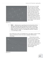
Robin Wood | Modify, Translate, Rotate | Beginner
Using the Bend Tool (and Other Similar Tools)
The various Modify tools, like Bend, Twist, Vortex, and so on, all work by
placing the cursor in the viewport perpendicular to the one in which you want
the modification to take place, just like you would with the Rotate tool.
So, to bend this flower petal, select the polys (or points) you want to modify,
place the Bend tool in the Top viewport, and carefully drag it toward the top,
making sure that the polys remain aligned. (Symmetry will help with this, if
you’re bending something that has it.)
Modeling | 123
Modify, Translate, Rotate
Place the tool in the viewport perpendicular to the desired motion
To bend the bottom part in the opposite direction, select the desired poly-
gons, and click on the other Shape wedge in the Numeric panel. That changes
the direction of the bend. When you find that the polys you want to anchor your
bend are bending, while the ones you wanted to move are anchored, click on this
button.
Then move to the Top viewport again, and care
-
fully drag in the direction you want the curve to go; in
this case, down (toward –Z.)
124 | Chapter 4
Modify, Translate, Rotate
… and drag carefully in the desired direction to bend the object.
Click the Shape button to
change which polys remain
still and which curve to form
the bend.
To bend the sides of the petal up, select them and drag in the Right viewport.
You get the picture.
Modeling | 125
Modify, Translate, Rotate
Drag again to complete the bottom part of the bend.
Continue to drag in the viewport perpendicular to the desired bend.
All of these tools work this way. You can twist the petal by using the Twist
tool in the Right viewport, and so on, to give the petal any shape you want.
Then tap the Tab key to SubPatch it, and you’ll have a lovely, smooth petal.
Versions: 6.5-8
322
Wes “kurv” Beckwith, William “Proton” Vaughan | Modify, Translate, Rotate | All Levels
Lining Up Points
I used to do CAD-style work in CorelDRAW a few years back. LightWave
was a stretch for me to learn at first. One great thing I learned was that if you
need more than two points to be in a straight line you can accomplish this easily.
Make sure mode is set to Action Center: Mouse by pressing Shift+F5.
Simply select the points you want to line up in the correct viewport. Then
choose the Stretch tool, choose where you want the points to line up to, hold
down the Ctrl key, right-click and hold your mouse, and move the mouse until
all the points are in a line. Voilà!
Also, if you know the exact position where you want the points to line up,
you can simply tap “v” (or go to Detail>Points>Set Value in either 7.5 or 8.0) to
open the Set Value dialog that allows you to choose an axis, and type in the
value. For instance, you can place all the points at –.5 m on the x-axis by choos
-
ing x as the axis in the dialog and typing –.5 into the field. Hit OK, and it’s
done!
Versions: 5-8
323
Robin Wood | Modify, Translate, Rotate | All Levels
Absolute Size
If you need to make something an exact size after it’s been created, Absolute
Size is the tool for you. You’ll find it on the Modify tab under Transform: More.
When you click it, a dialog opens that allows you to resize the object any way
you want to. Choose Locked if you want to keep the proportions, or Independent
if you don’t. Choose your reference to determine where the object will end up
after the resizing operation, and what you would like to use for the Action Cen
-
ter. (This works the way most tools of this sort work in LightWave. For instance,
if you choose Bounding Box for the reference, and Xc, Y-, Zc, the object will
shrink (or grow) from the bottom center of a bounding box that describes its out
-
ermost points on the three axes.) Then pick your size in X, Y, and/or Z.
126 | Chapter 4
Modify, Translate, Rotate