LightWave 3D 8 Lighting Wordware game and graphics library phần 2 pps
Bạn đang xem bản rút gọn của tài liệu. Xem và tải ngay bản đầy đủ của tài liệu tại đây (851.49 KB, 55 trang )
forest fire approaching your town? Think through all these examples and
listen to your own emotional reactions to each one.
Atmospheric conditions can send a scene down a desired emotional
path, easily and unconsciously drawing the audience into a desired
mindset.
You should now be able to view a scene or photograph and under
-
stand that atmospheric conditions play an important part in many cases,
primarily outdoors. But don’t forget the smoky room or the steamy
shower. These are also atmospheric conditions that play a part in how
you will light your scene. Lights interact with these elements to create
an effect known as volumetric lighting in which the light beams become
visible due to their interaction with the atmospheric particles of smoke
or steam. There is more discussion of volumetrics later.
Let’s sum up the questions we ask when examining a scene for lighting.
•
Is the scene an interior or exterior (or both)?
•
What time of day is depicted in the scene?
•
What time of year is depicted in the scene?
•
What are the atmospheric conditions present in the scene?
Remembering these four areas of consideration should provide you with
great assistance in identifying just what the lighting conditions are in
your scene.
Hopefully by now you are able to define the temporal and spatial
issues that are present in various lighting environments. You should now
be able to observe a lighting environment and define the time of day (if
relevant), time of year (if relevant), atmospheric conditions (if relevant),
and whether the environment is interior or exterior.
··································
What, Where, When?
27
Chapter 3
Light Sources
This chapter will help you understand some specific types of light
sources. There are many different sources of light in the world. Each has
similarities and differences and must be handled appropriately in Light
-
Wave. Once you understand these specific light sources, you should be
able to look at any light source and understand its properties.
In the real world, a light source is defined as the direct source of illu-
mination. The sun is a light source. So are a fluorescent tube, a lightbulb,
a candle, and a tiki lamp. Described another way, physicists consider
light sources to be events in which energy is spent, resulting in the
emission of photons. Since this is not a physics manual, we will ignore
that particular law. Apologies to physicists everywhere.
For the purposes of this book and CG lighting in general, a light
source is also defined as an indirect source of illumination such as diffuse
or reflected light. The sky, for example, is considered a diffuse light
source, although all of its light comes indirectly from the sun. Reflected
light such as light from a mirror and diffuse reflected light, also known as
radiosity, is considered a light source in the CG world.
There is a good reason for this. Rather than create a physically accu
-
rate lighting environment in which diffuse light sources are actually
diffused from the direct source, and in which reflected light is actually
reflected 20, 30, or 100 (or infinite!) times, bouncing around the environ
-
ment, we use cheats and tricks to create these effects. Why? There isn’t
enough rendering time. Computers are not fast enough. Deadlines must
be met. Rendering diffuse and reflecting light sources accurately is very
CPU intensive and takes a great deal of time. So instead of actually dif
-
fusing the light from the sun by creating a physically accurate diffusion
event the size of the earth’s atmosphere, we add a local diffuse light
source that only affects the area within view of the camera. Instead of
actually reflecting the light from the sun, we use no reflection but
instead add a light source at the reflection point to simulate the effect.
Usually the results are acceptable and save us hours per frame of ren
-
dering time.
28
What’s the big deal about rendering time if the final render looks
great? You’re right. If you’re working on a personal project at home and
you want to leave your dual proc machine rendering for six weeks to get
a great four-second shot, go for it. But if you are working in a production
environment, you are probably not the only artist trying to get frames
rendered. If you hog the render farm with frames that take an unreason
-
able amount of time to render, you risk missing your deadline (and
incurring the wrath of the other artists). Trust me on this — CG artists
can be very creative with their punishment. Many tricks and tips are
covered in this manual to help you create the best “bang for your buck.”
These tricks do not work for every situation, but you will find that most
cases do not require the long render times, and you won’t have to find
out what punishments are inflicted on “render hogs.”
Sunlight
Intensity High to medium
Color Warm spectrum
Direction Side to top
Diffuseness Low
Shadow Usually very hard to soft
Shape Usually omni
Contrast High
Movement Usually imperceptible
Size Medium or small
The first and most common light source in the world is the sun. It is the
source of almost all light on our planet, actually. All the photochemical or
electromagnetic energy in the world originates with radiations from the
sun. As a lighting artist you are most certainly going to run into situa
-
tions where you will have to create sunlight for your scene.
This section deals only with direct sunlight — the stuff you see
when the sun is visible in the sky, the stuff that gives you a sunburn, the
bright light that blows out your photos and makes you squint, the stuff
your mother told you not to look at during a solar eclipse.
A very simplistic description of sunlight may refer to it as a distant
light source in which all the light rays are parallel and all the shadows
are hard. The parallel light rays mean that objects in the path of the sun
-
light will cast shadows that are exactly the same size as the object itself.
Some describe the sun as a point source that emits light omnidirec
-
tionally and is so distant that the light rays reaching the earth merely
appear to be parallel because the angle is so negligible as to be
······································
Light Sources
29
imperceptible. Some see the sun as an area source. In other words, they
see the sun as a flat disc in space, the whole surface of which is emitting
light omnidirectionally. Area sources behave as diffused sources and
therefore result in soft shadows. In truth, all these descriptions are ele
-
ments of how sunlight behaves.
Chapter 3
·······································
30
Figure 3.1: A distant light with parallel rays and hard
shadows.
Figure 3.2: A point source with omnidirectional rays
and hard shadows.
Before we deal with lighting types used in CG, let’s discuss reality. In
reality, all light sources are omnidirectional area sources. In reality, there
are no point lights or distant lights like the tools we use in LightWave.
This is because 1) all light sources have dimension and volume and can-
not, therefore, be nondimensional point sources, 2) all light sources have
limited dimension and cannot, therefore, emit the same parallel beams in
the same direction regardless of your position in space, and 3) no light
sources emit only parallel light rays.
“But wait,” you say, “a candle is a point source and so is an LED.”
Actually no. Candles and LEDs are small area sources, to be sure,
but a point source by definition emits all light omnidirectionally from a
single nondimensional point in space. There are no such light sources in
existence. Candle flames have dimension; so do lightbulb filaments. This
means that every nondimensional spatial point within the shape of the
flame and on the filament is emitting light in every direction, producing
not only an area source but a diffused result.
“Who cares?” you say. “If you can’t tell, what’s the difference?”
The difference is in the details. But it is true that sometimes you
can get away with using a distant light or a point light to simulate the
sun.
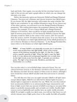
Note: In Part III, we deal extensively with different ways of cre
-
ating sunlight and skylight using different light types for different
quality results and different render times.
······································
Light Sources
31
Figure 3.3: An area source with omnidirectional rays
and soft shadows.
The sun is larger than the earth. This means that there are light rays
running exactly parallel to each other that cover the entire sunward face
of our planet.
In addition to these parallel rays, there are nonparallel light rays coming
from the entire earthward face of the sun in every direction, some of
which reach the earth.
Of those light rays that reach the earth, some come from near the
edge of the sun’s disc, some come from the middle, some come from
everywhere on the sun. Since the sun is larger than the earth, some
rays will angle behind the earth while rays originating near the center of
the disc will either hit the earth or angle away from the earth after they
pass it. A lunar eclipse is a good example of this effect.
Sunlight acts this way on every object on the earth but on a smaller
local scale. The penumbra is the area behind the earth — or building or
chair or anything on earth — where there is partial shadow. It is partial
shadow because while some sunlight is blocked out, the sun is so large
that some of the light still reaches that area behind the object. The
umbra is the area behind the earth — or building or chair — where
there is no sunlight at all and the shadow is complete. This is why you
can look at a chair leg with sunlight shining on it and see near the leg
that the shadows are dark and hard-edged. But the farther away you
move from the leg, the softer and lighter the shadows become. It is
because the sun is so much larger than the chair leg that some of the
light manages to reach those areas behind the leg.
Chapter 3
·······································
32
Figure 3.4: If the sun’s rays were all parallel, all shadows
would behave the way those in this image are behaving, all
parallel and hard-edged, and the shadow would remain
exactly the same size as the object that cast it.
So hopefully you now grasp how the sun emits parallel rays similar to a
distant light in LightWave, emits omnidirectional light similar to a point
light in LightWave, and emits light over an area similar to an area light in
LightWave. LightWave’s area lights are closest, but they, too, fall short
······································
Light Sources
33
Figure 3.5: This image demonstrates how the sun’s light acts
on the earth and especially how sunlight gets behind the
earth. Note that as less of the sun’s surface is visible behind
the earth, the light intensity falls off. The area of falloff is
very narrow nearest the earth and grows larger the farther
from the earth you look. Effectively, since the earth is the
shadow-casting object, it is the focal point of the shadow,
which grows softer as you get farther away. Remember this.
It is crucial!
Figure 3.6: This image uses an area light far enough
away to create natural hard shadows near the chair and
natural soft shadows farther away. This simulates the
way sunlight acts on an object here on earth.
since they are planar and the sun is a volume; however, this physical
inaccuracy will almost never be an issue.
“OK,” you say, “if sunlight doesn’t work exactly like distant, point,
or area lights in LightWave, then why do we have these types of lights in
LightWave?”
The answer is that these lights calculate much more quickly than a
physically perfect model, and that often, the precise physical accuracy
may be unimportant or unnoticeable. The camera may be framed on an
area very close to the object so that only the hard shadows are visible
and the more distant softening shadows are out of frame. In this
instance, you could use a distant light or even a point light or a spotlight
to create the bright light and hard shadows needed to simulate sunlight.
Or there could be enough motion in the shot that physically precise
shadows would never be noticed.
Now that you understand how sunlight really acts on objects, you
will have to look at the requirements of your shot and decide how far to
take it and how far to fake it. The trade-off is that the most physically
accurate solutions generally take longer to render. If the final render is
no different whether you use a distant light or an area light, then there is
no point in using the area light. Do the quick renders. Make the boss
smile.
Skylight
Intensity Medium to low
Color Cool spectrum
Direction Omni
Diffuseness High
Shadow Soft
Shape Usually none
Contrast Low
Movement Usually none
Size Very large
Skylight is the ultimate filler when it comes to lighting. Whether it is
bright, blue sky or dark, gray clouds, skylight is a diffuse source that
epitomizes the expression “global illumination.” This is because skylight
is global. It is a big ball around the earth that emits light omnidirec
-
tionally during the day. It is a gigantic, spherical area light. It is a lumi
-
nous ball turned inward. Surprise! I have just described three different
ways in which skylight can be simulated by LightWave.
Chapter 3
·······································
34
Skylight produces only soft shadows, yet it is remarkably similar to
sunlight. Skylight is sunlight that has been diffused and spread around
randomly in many directions. There are two primary differences
between skylight and sunlight. First, sunlight appears mainly unidirec
-
tional, or traveling all in parallel rays, creating hard shadows. (I know we
just spent a whole section describing how sunlight is omnidirectional,
but compared to how random skylight is, sunlight appears relatively uni
-
form.) The sky’s light is omnidirectional relative to any place on the
earth’s surface, except where it is occluded by the earth, so it causes
only soft shadows. Look at the underside of your chair outside on a
cloudy day. See the shadows? Remember that objects cast shadows?
What object is casting that shadow? Is it the chair? Partly. Mostly, how
-
ever, it is the planet beneath your feet. Think of it this way: The sky is a
big, luminous globe. You can’t see most of it because the planet is in the
way. If the whole ball of sky were not occluded by the planet (in other
words, if you were just floating in a giant ball of luminous atmosphere
with no planet), then everything would be lit from all angles. The reason
most objects on the earth are dark on the bottom is because the earth is
getting in the way and creating a shadow. Think also of nighttime. Night
occurs because the earth is casting a big shadow and half the planet is
sitting in it. This is an important consideration when building a diffuse
global lighting solution. The earth is a big, fat shadow-caster. Don’t for-
get it. Let’s look at our chair again and see what a global light source like
the sky will do to the shadows.
······································
Light Sources
35
Figure 3.7: You can see in this image that there are no dark
“umbra” type shadows. The area under the chair does have a
soft shadow because some of the light is occluded by the chair,
but some amount of light reaches everywhere. This is because
light is coming in from all directions. So a soft shadow is not
about whether or not light is reaching the spot but how much of
the total light is reaching the spot.
Whereas the sun’s light comes from one general direction and causes
shadows on the opposite side of the object, skylight comes from all
directions. There is no complete shadow from any direction as long as a
line can be drawn between that point and any portion of the sky. This
means that under skylight, most of the shadows are of the penumbra
type. This is also known as “accessibility” lighting. If any part of the
light source has “access” to any part of a surface, then there is some
light. If a great deal of the light source has access to the surface, there is
a great deal of light. If very little of the light source has access to the
surface, there is very little light.
Incandescent
Intensity Variable
Color Warm spectrum (can be altered)
Direction Any
Diffuseness Usually low
Shadow Very hard to soft
Shape Any
Contrast High to medium
Movement Any
Size Any
Incandescent sources can be as simple as a household frosted lightbulb
or a tiny halogen lamp. They can also be a burning fireplace, a candle, a
stove element, an electric heater, or even a tiny LED. Incandescence
involves the expenditure of energy at high temperature, resulting in
light. So anything that is so hot it emits light can be said to be incandes
-
cent. Lava flows, for example, or fire embers, or a lit cigarette are all
incandescent. Fireflies are not.
Note: Some organisms emit light through photoluminescence.
This happens because the organisms absorb infrared or ultraviolet
radiation from sunlight during the day and then emit it when they
move. We’re not going to deal with the science of photo or chemi
-
cal luminescence. Suffice it to say that by the time you finish this
book, you will be able to look at any light source, identify its prop
-
erties, and simulate it in LightWave.
Because incandescence is caused by high heat, most incandescent light
is on the warm or red side of the spectrum. Of course, clever stage and
film lighting designers alter the color of incandescent light by placing a
Chapter 3
·······································
36
colored filter in front, which means you can get blue light out of an
incandescent light source. Bear in mind that larger incandescent sources
are likely to cause softer shadows, while smaller incandescent sources
usually cause harder shadows.
Fluorescent
Intensity Medium to low
Color Cool spectrum (can be altered)
Direction Any
Diffuseness High to medium
Shadow Usually soft
Shape Usually none
Contrast Usually medium to low
Movement Usually none
Size Usually medium to small
Fluorescent sources include, coincidentally, fluorescent lamps, neon
lamps, computer monitors, televisions, and any other sources created by
making a phosphor glow due to particle bombardment or electrical exci-
tation. Technically, only lights containing fluorine are fluorescent. While
neon lights, monitors, and fluorescents are technically different from
each other, for the purpose of CG lighting their properties are similar
enough that they will be dealt with pretty much identically, except for
color and shape. For brevity we will refer to all such sources as “fluores-
cent” sources.
The primary difference between incandescent and fluorescent light,
as far as we are concerned, is that incandescent sources are considered
direct light sources and usually result in hard shadows, while fluorescent
sources are considered diffused light and usually result in soft shadows.
Note: Hard shadows refers to hard-edged or “sharp” shadows
while soft shadows refers to fuzzy, unclear edges on the shadows.
Reflected
Intensity Any (depends on physical source)
Color Any
Direction Any
Diffuseness Usually low
Shadow Usually hard
······································
Light Sources
37
Shape Any
Contrast Usually high
Movement Any
Size Any
Reflected light sources have distinct differences from other sources.
Light reflected from a mirror, a water surface, a window, or other highly
reflective surface displays many of the properties of the original light
source. For example, sunlight reflecting off a pool onto a wall will retain
most of the hard-edged properties as well as a good portion of the inten
-
sity, color, shape, and contrast. Skylight reflecting off the pool will retain
all its diffuse properties as well. But adding light-reflective properties
(called caustics) to a surface means a huge increase in rendering time. It
is often simpler and quicker to place a new light at the place where the
reflection would occur, replicate the properties of the original source
(except for direction), and aim it in the direction that the reflected light
would go.
Diffuse Reflected
Intensity Any (depends on physical source)
Color Any
Direction Any
Diffuseness High
Shadow Soft
Shape Usually none
Contrast Usually low
Movement Any
Size Usually large
Diffuse reflected light is referred to in CG terminology as radiosity. What
this means is that light coming from any source will touch a surface of
some kind, then part of that light will reflect away, perhaps touching
another surface and reflecting again. Radiosity reflections can continue
infinitely until all photonic energy has been spent.
As with all reflections, the angle of incidence (the angle at which the
light reaches the surface) must be equal to the angle of reflection. In the
case of diffuse reflection, the surface is usually uneven or rough, causing
the light rays to reflect away in numerous directions and effectively dif
-
fusing the reflected light.
A good example is that of sunlight illuminating the pavement in
front of a wall. There is no direct lighting on the wall, and it is shaded by
an overhanging roof. Blue skylight is filling in and lighting the wall, but
Chapter 3
·······································
38
there is a brighter, more yellow light on the wall coming from below.
This is the light reflecting off the pavement and up onto the wall. The
pavement is very uneven and so the light reflection is very diffuse. This
is the most common form of lighting in nature. More than sunlight or
skylight, the world is illuminated by this type of lighting. The light rays
in nature can reflect from surface to surface an infinite number of times,
radiating from pavement to wall, back to pavement, to nearby fences,
trees, or whatever. Each time the sunlight strikes a surface, it diffuses
into many new directions, so the more reflections that occur, the lower
the overall intensity of the reflection becomes. As a lighting artist, you
will learn to have a love-hate relationship with radiosity. On one hand, it
adds a realism to LightWave’s renders that no other tool can match. On
the other hand, the render times can become galactic very quickly,
sometimes making radiosity impractical. We will spend some time later
on discussing how best to fake radiosity and when it is best to use the
real deal.
A Note about Proportion and Scale
These light sources have all been described according to their normal
world scale, that is, as though you were the viewer standing there, look-
ing at them. But the camera often sees things differently. What if, for
example, there was a close-up of a candle? Well then, that incandescent
source would not be tiny. It would be a major consideration in your light-
ing setup. What about the skylight? It is global and very large, unless
you can only see a small square of it through a skylight. So in many ways
the properties we have assigned to these light types are highly variable
and will depend on the situation. Don’t get stuck into one way of think
-
ing about a light type or its properties. Infinite possibilities exist. Be
prepared to create a technique never before tried for a situation never
before seen. There are no rules. Look at the situation, analyze the light
sources and their properties, and then proceed.
By now, it is probably becoming obvious to you that many different light
sources can behave in many different ways and can display a number of
variable properties. Just like the analogy of the auto mechanic who
knows everything about the car, but only thinks about fixing one system
at a time, if you take each light source one at a time and analyze its par
-
ticular properties and behaviors in a photograph, you should have
enough information to understand what properties are present and you’ll
be able to add each light source, one at a time, into your scene. Later in
······································
Light Sources
39
this book, we discuss the tools we can use to simulate each of the many
properties that we’ve discussed.
In this chapter, we have covered the properties of a number of spe
-
cific real-world light sources. Hopefully by now you can analyze each
light source type and recognize them in a photograph.
Chapter 3
·······································
40
Chapter 4
Surface
Considerations
Your job as a lighting artist is to light objects. These objects have sur
-
faces. In order to enable your lights to interact properly with your
surfaces, you will need to understand some surface properties that per-
tain to lighting. This is, by no means, a definitive guide to texturing. For
that, I recommend you consult LightWave 3D 8 Texturing by Leigh van
der Byl. This chapter covers some of the basic surface properties you
need to consider when building your lighting environment, since the
look of light and your texture properties are so closely interrelated. By
the time you finish this chapter you should have a basic understanding of
how color, specularity and glossiness, reflectivity, diffuseness, and lumi-
nosity affect your textures and your lighting.
Color in the Real World
The first and most significant property we discuss is color. We get into
the dark art of color mixing in Chapter 19, but for now, suffice it to say
that in the real world, the solid colors found on surfaces interact differ
-
ently with colored light than they do by mixing other color into the
surface. For example, if you mix paint colors of primary red, primary
blue, and primary yellow, you will, theoretically, get black paint. If you
mix light colors of primary red, primary green, and primary blue, you
will, theoretically, get white light.
41
Note: The reality of paint and light in the real world is that it is
practically impossible to create true primary colors. A primary color
is one that contains only a single wavelength. While it is possible
to create this digitally, it is very difficult in the world of chemicals
and pigments. So in reality, if you were to take paints labeled pri
-
mary red, yellow, and blue, you will probably get a brownish gray.
Keep this in mind when painting textures digitally, especially if you
are trying to make it look photo-real.
The most obvious difference between solid pigment colors and lighting
colors is that the primaries are different. For solids, it is red, yellow, and
blue. For light, it is red, green, and blue. We deal with the reasons for
this in Chapter 19, which covers color in depth.
Color is measured in wavelength. If we look at a spectrum of visible
light, we see red colors at one end and blue colors at the other end. Blue
and violet have the shortest wavelengths, while the red end has the lon-
gest wavelengths. Our eyes perceive these wavelengths and translate
them into different colors. Various surfaces and materials in the real
world will either absorb or reflect certain wavelengths based on the sur-
faces’ own physical properties. A surface that absorbs only red and green
wavelengths of light, for example, will appear mostly blue because it is
reflecting the blue part of the spectrum. Furthermore, the reflected blue
wavelengths will then reflect on another nearby surface. This is why if
you put two objects of different colors near each other in bright light,
they appear to gain some of the reflected color of each other. In the
world of CG, this effect is called radiosity, or diffuse reflection.
Note: It’s the old trick of putting a buttercup under the chin to
see if the yellow light reflects on the underside of the chin. OK,
maybe you didn’t do that as a child, but I did. The trick was that if
you saw yellow light reflected under the chin, it meant you liked
butter. Hey, it makes sense when you’re six.
Be aware that if you shine a yellow light onto a blue surface, there will
be little reflected light because the incoming wavelengths are opposite
the surface wavelengths on a color wheel. This means that the yellow
light is in the range most likely to be absorbed by the blue surface. Yel
-
low light is yellow because it is missing most of the blue wavelengths,
Chapter 4
·······································
42
so there is little light left for the blue surface to reflect. More detail on
color wheels, mixing, and the behavior of colors is in Chapter 19. Under
-
standing the difference and interactions between solid colors and
lighting colors can be confusing at first. This is all covered in Chapter 19
as well.
Specularity and Glossiness
If you were a physicist, you might comment that the reflectivity of a sur
-
face is based on its specularity. In the real world, specularity refers to the
surface properties of an object that cause light to reflect in a directed
manner, as from a smooth, polished surface, so that parallel light rays
reaching the surface will still all be parallel light rays when reflected. In
the real world, high specularity usually refers to mirror-like and other
highly reflective surfaces.
·································
Surface Considerations
43
Figure 4.1: This image demonstrates how a very smooth surface
reflects light information. The light information retains its original
form and is therefore still easy to identify as an image. This is
what occurs in a mirror. In the real world, shininess (or
glossiness), reflectivity, and specularity are the same thing.
In LightWave, however, specularity and reflectivity are two entirely dif-
ferent animals.
Note: Specularity and glossiness in LightWave are misnomers.
The control we know as Specularity really should be called “Specu
-
lar Intensity” because it refers to the illumination intensity of the
specular highlight, or how bright it is. Glossiness should actually
be called “Specularity,” because a high glossiness is a smaller,
sharper, more defined specular highlight, indicating a smoother
surface, while a low glossiness is a larger, softer, more diffused
specular highlight, which indicates a rougher surface texture. The
Specularity control in LightWave actually is like a light intensity
control that only affects the intensity of the specular highlight but
not the illumination value.
Specularity in LightWave refers to the “shininess” of a surface. It’s like
that bright, white highlight you see on a polished apple. It refers to how
much “brightness” or “lighting” information is reflected. But specularity
in LightWave does not include reflective information. Reflectivity,onthe
Chapter 4
·······································
44
Figure 4.2: This image demonstrates how a rough surface
reflects light information. The light information does not retain its
original form and is scattered. The light information is no longer
identifiable as the original light information. This occurs on any
rough surface such as a sheet of paper or a wall painted with a
matte paint.
other hand, refers to how much clear image information is reflected. In
the real world, these two are inextricably tied together because image
information is light information. The light seen in the mirror has
reflected off the surface. One great reason why specularity and reflec
-
tivity are separate in LightWave is that you can dramatically decrease
rendering times by using only one or the other. A marble, for example,
is usually highly specular. This means that there’s a nice bright highlight
on the surface, and it is reflecting all the image information around it.
But if you are standing in a room and there are a few marbles on the
floor ten feet away from you, it is unlikely that you will clearly see any of
the image information unless you look very closely. Why, then, spend
time calculating it, when a nice specular light hit will complete the illu
-
sion quite adequately? For many surfaces, you will use specularity only
and never turn on reflectivity, especially for surfaces with low
specularity such as rough plastic or perhaps even skin. They both have
some shininess, but the reflective value is so low and the reflected
image so diffused by the rough surface that you will never really see an
image reflected. You can save a good deal of render time by simply not
calculating the reflectivity.
·································
Surface Considerations
45
Figure 4.3: This image displays various levels of specularity.
The Specularity setting in the Surface Editor determines the
brightness or intensity of the specular highlight and really
should, therefore, be named “Specular Intensity.”
Reflectivity
Reflectivity in the real world refers to how much light is not absorbed by
a material. For example, coal is not very reflective, but snow is highly
reflective. A mirror is highly reflective, but a cast-iron frying pan is not.
Colloquially, however, we think of reflectivity as meaning how well
you can see the reflection of an image in a surface. We think that a mir-
ror is highly reflective, but a white wall is not. In truth, both the mirror
and the white wall are highly reflective. The difference is that one mate
-
rial diffuses the light that it reflects, and the other does not. If you go
back and look at the images in the previous section of this chapter, you
will understand that the white wall has a very rough surface at the
microscopic level, and so the image information is scattered so widely
that we can no longer discern any image information in the reflection.
However, a mirror’s surface is so smooth that the image information is
not scattered at all and the reflected light is in almost the same form as it
was before striking the mirror’s surface; therefore, we can see the
image information clearly.
In LightWave, however, reflectivity refers only to image reflection
and has nothing to do with diffuseness, specularity, or glossiness, all of
which are separate controls in the LightWave Surface Editor panel.
Chapter 4
·······································
46
Figure 4.4: This image displays various levels of glossiness.
The Glossiness setting in the Surface Editor determines
smoothness (or specularity) of the surface and really should,
therefore, be named “Specularity.” Note that the lower the
Glossiness setting, the more spread out the specular highlight
becomes. Wider specular highlights indicate a surface that is
rough and is diffusing the light information more.
So this means that you use the Reflectivity setting if you specifically
want to reflect the surrounding environment in your object’s surface,
such as a mirror, a glass, or a shiny marble floor, but you can leave it off
for diffuse surfaces that don’t reflect images.
Note: In order to have reflection work, you must enable Ray
Trace Reflection in your Render Options panel.
Diffuseness
In LightWave, diffuseness is a surface property that refers to the amount
of light that acts on a surface. For example, a beach ball has a high dif
-
fuseness. When light hits it, you can see that it is brightly lit and easily
visible. Technically, we are saying that because light hits the object and
is widely diffused, or dispersed, the object is easy to see from any direc
-
tion because a great deal of light is reflecting from its surface in all
directions. As another example, a mirror has very low diffuse value.
While it does reflect all the light away, it is not diffused. The reflections
are direct. All you see is a reflection of whatever image is before the
mirror. It is technically possible in the real world for a material to have
no reflectivity and no diffuseness. A material such as this would be invis
-
ible because no light is reflected or diffused from its surfaces. The only
item known to have these properties is a black hole, which does not
reflect or diffuse light from its surface. But this is mainly due to gravity
rather than surface properties. If black holes did not have the immense
gravity necessary to suck in light, then they would be visible because all
·································
Surface Considerations
47
Figure 4.5: This image demonstrates the Reflectivity value at
different levels. The higher the value, the more image
information is reflected in the texture. Very simple.
surfaces have some measure of diffuse value. Even the surface of the
sun has a diffuse value, but it is completely overwhelmed by the lumi
-
nosity of the sun.
In LightWave, if you wished to remove shadows from an object’s
surface, you could accomplish this by lowering the diffuse value of the
surface and by increasing the luminosity value. Or if you want to look at
it another way, in the real world, a white surface like a piece of paper has
a high diffuse value because it diffuses a great deal of light and is, there
-
fore, highly visible. A black surface, on the other hand, has a low diffuse
value because it diffuses very little light. The easiest way to envision
this is by imagining driving down a dark road at night. If a person is
wearing all white clothes, your car headlights will pick him up sooner
and he will be visible much farther away because his clothes have a high
diffuse value. Someone dressed entirely in black might not be seen until
you are very close, because very little light is being diffused back toward
you, and therefore there is very little light information entering your
eyes. The person is very difficult to see.
Chapter 4
·······································
48
Figure 4.6: The texture settings on all four balls are exactly the
same except for the diffuseness values. Diffuseness indicates
how much of the light received by the surface is reflected back.
A low diffuseness value means very little light is reflected,
while a high diffuseness value means a great deal of light is
reflected. The more visible light that is reflected by the surface,
the more visible it is to the human eye.
Luminosity
Some objects in your shot will have surfaces that emit light. These sur
-
faces are said to be luminous. In other words, they display the property
of luminosity. The surface of a lightbulb, for example, has a pretty high
luminosity value. So does a computer monitor. Any surface that emits
light can be said to be luminous. NewTek, the makers of LightWave, has
provided us with some great tools to simulate the luminosity of a sur
-
face. One is the luminosity value found on the Surface Editor panel. This
luminosity value brightens the surface, eliminating shadows as though
the brightness were overpowering any shadows. This value, however,
does not actually emit light. It does not actually transmit illumination to
nearby surfaces unless you turn on LightWave’s radiosity. In this case,
the luminous surface does emit light to nearby surfaces.
·································
Surface Considerations
49
Figure 4.7: In this image, the texture values are the same for
all four balls, except for luminosity. The higher the luminosity
value, the more light a surface is apparently emitting. A
lightbulb, for example, has a low luminosity value when it is
turned off but a high luminosity value when it is turned on.
Note how, as the luminosity increases, the shadows are filled
in. Just for the fun of it, I turned on single-bounce Monte Carlo
radiosity for this render so that the balls emit light onto nearby
surfaces.
I hope this chapter has helped you understand some of the surface prop-
erties we deal with when lighting our scenes. Lighting is only half about
the lights we use and how we use them. The other half of lighting is
about the surfaces that we light. The surface properties have a direct
effect on how the light looks when it reaches them.
Chapter 4
·······································
50
Figure 4.8: This image demonstrates the use of luminosity, diffuseness,
specularity, and reflectivity. All other settings are at 0%.
Chapter 5
Studying Light
This chapter deals with the observation of light in the real world. By the
time you have finished this chapter, you should be able to observe and
identify the light properties specific to various types of natural and artifi
-
cial light sources and to shadows.
Being a great lighting artist is all about understanding how real light
works so that you can recreate it in your virtual environment. The only
way to really understand the nature of light and shadows is to study it.
Studying light is really as simple as it sounds. As an artist, you wish
to recreate something in the medium of your choice. If you are a painter,
you might wish to paint a portrait. This requires you to understand
human skeletal and muscular structures, the behavior of fabrics, the visi-
ble properties of skin, iris, lens, and hair. Perhaps there is a chair in the
portrait. You must understand the grain of the wood and the properties
of the velvet or leather upholstery. You must understand how the light
will play off each surface, how the specular highlights and reflections
should look, how shadows are formed and where, what the diffuse
reflected light will do to the underside of the chin and the nose, how
back-lit cotton will react translucently, and so on.
Studying to be an artist means studying the art of the masters. It
also means studying the natural elements that come together to create
an image. In this case, the element we are talking about is light. Light
deserves as much study as any other element of your composition —
perhaps even more. In the world of CG, your lighting is mission critical
to making your shot look real. So start by spending some time just look
-
ing around. You don’t have to go to a gallery. Light is everywhere, in
every form. A trick used by many lighting designers is to hold up one
hand or a piece of paper and stare at it, turning it over and around to see
how the light plays across it. Look at the shadows and where they are,
what color they are, and what sort of light is filling the shadows. Check
out the contrast, the shape and softness of the shadows, and the direc
-
tion of the light source. Can you identify all the light sources around just
51