Beginning AutoCAD 2002 Episode 9 pdf
Bạn đang xem bản rút gọn của tài liệu. Xem và tải ngay bản đầy đủ của tài liệu tại đây (959.51 KB, 30 trang )
3 Activity 26: The light bulb
This was one of my first array exercises and has proved very popular in previous AutoCAD
books. It is harder than you would think, especially the R10 arc. The basic bulb is copied
and scaled three times. The polar array centre is at your discretion. The position of the
smaller polar bulb is relative to the larger polar array, but how is it positioned? – your
problem. No hints are given on how to draw the basic bulb.
4 Activity 27: Bracket and Gauge
The bracket is fairly easy, the hexagonal rectangular array to be positioned to suit
yourself. The gauge drawing requires some thought with the polar arrays. I drew a
vertical line and arrayed 26 items twice, the fill angles being +150 and –150. Think about
this!! The other gauge fill angles are +140 and –140. What about the longer line in the
gauge? The pointer position is at your discretion. Another method is to array lines and
trim to circles?
5 Activity 28: Pinion gear wheel.
Another typical engineering application of the array command. The design details are
given for you and the basic tooth shape is not too difficult. Copy and rotate the second
gear wheel – but at what angle? Think about the number of teeth. I realise that the gears
are not ‘touching’ – that’s another problem for you to think about.
6 Activity 29: Propeller blade.
Draw the outline of the blade using the sizes given. Trimmed circles are useful. When
the blade has been drawn, use the COPY, SCALE and polar ARRAY commands to produce
the following propeller designs:
a) 2-bladed at a scale of 0.75
b) 3-bladed at a scale of 0.65
c) 4-bladed at a scale of 0.5
d) 5-bladed at a scale of 0.35
Note that the four- and five-bladed designs require some ‘tidying up’.
7 Activity 30: Leaf design
Draw the leaf using the reference sizes given. Mirror effect is useful for the outline then
2D solid or hatch. The arrays are with a
1
/
4
size object. The angular array requires some
thought for the angle and the row/column offsets.
The ARRAY command 233
Beginning with AutoCAD 2002.qxd 14/06/2002 19:07 Page 233
Changing properties
All objects have properties, e.g. linetype, colour, layer, position, etc. Text has also
properties such as height, style, width factor, obliquing angle, etc. This chapter will
demonstrate how an object’s properties can be changed, and this will be achieved by a
series of simple exercises.
1 Open A3PAPER with layer OUT current, toolbars to suit and refer to Fig. 35.1.
2 Draw a 40 unit square and copy it to six other parts of the screen.
3 a) At the command line enter LTSCALE <R> and:
prompt Enter new linetype scale factor and enter: 0.6 <R>
b) At the command line enter LWDISPLAY <R> and:
prompt Enter new value for LWDISPLAY and enter: ON <R>
Chapter 35
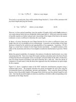
Figure 35.1 Changing properties exercise.
Beginning with AutoCAD 2002.qxd 14/06/2002 19:07 Page 234
Command line CHANGE
1 At the command line enter CHANGE <R> and:
prompt Select objects
respond window the second square then right-click
prompt Specify change point or [Properties]
enter P <R> – the properties option
prompt Enter property to change [Color/Elev/LAyer/LType/ltScale/
LWeight/Thickness]
enter LA <R> – the layer option
prompt Enter new layer name<OUT>
enter HID <R>
prompt Enter property to change, i.e. any more property changes
respond right-click-Enter.
2 The square will be displayed as brown hidden lines – fig. (b).
3 Repeat the CHANGE command line entry and:
a) objects: window the third square then right-click
b) change point or properties: enter P <R> for properties
c) options: enter LT <R> for linetype
d) new linetype: enter CENTER <R> for center linetypes
e) options: right-click/Enter to end command.
4 The square will be displayed with red centre lines – fig. (c).
5 Use the command line CHANGE with:
a) objects: window the fourth square then right-click
b) change point or properties: enter P <R>
c) options: enter C <R> – the color option
d) new color: enter BLUE <R>
e) options: press <R> – fig. (d).
6 Use the CHANGE command with the fifth square and:
a) enter P <R> then LA <R> – the layer option
b) new layer: DIMS <R>
c) options: enter LT <R>
d) new linetype: CENTER <R>
e) options: enter: C <R>
f) new color: enter GREEN <R>
g) options: right-click/Enter – fig. (e).
7 With the command entry CHANGE:
a) objects: window the sixth square and right-click
b) change point or properties: activate properties
c) options: enter LW <R> – the lineweight option
d) new lineweight: enter 0.5 <R>
e) options: press <R> – fig. (f).
8 CHANGE <R> at the command line and:
a) objects: window the seventh square and right-click
b) activate properties
c) options: enter LT <R> then CENTER <R>, i.e. centre linetype
d) options: enter S <R> – the linetype scale option
e) new linetype scale: enter 0.5 <R>
f) options: press <R> – fig. (g).
Changing properties 235
Beginning with AutoCAD 2002.qxd 14/06/2002 19:07 Page 235
9 Compare the center linetype appearance of fig. (c) and fig. (g).
10 Menu bar with Format-Layer and:
a) make layer 0 current
b) freeze layer OUT then OK
c) only a yellow hidden line square and a green centre line square displayed?
d) thaw layer OUT and make it current.
11 Note
a) This exercise with the CHANGE command has resulted in:
fig. square appearance layer
a red continuous lines OUT
b brown hidden lines HID
c red center lines OUT
d blue continuous lines OUT
e green center lines DIMS.
b) I would suggest to you that only fig. (a) and fig. (b) are ‘ideally’ correct, i.e. the correct
colour and linetype for the layer being used. The other squares demonstrate that it is
possible to have different colours and linetypes on named layers. This can become
confusing.
The change point option
The above exercise has only used the Properties option of the command line CHANGE
command, the there is another option – change point.
1 Draw two lines:
a) start point: 20,140 next point: 60,190
b) start point: 70,140 next point: 90,180.
2 Activate the CHANGE command and:
prompt Select objects
respond pick the two lines then right-click
prompt Specify change point or [Properties]
respond pick about the point 80,190 on the screen.
3 The two lines are redrawn to this point – fig. (h).
4 This could be a very useful drawing aid?
LTSCALE and ltScale
One of the options available with the CHANGE command is ltScale. This system variable
allows individual objects to have their line type appearance changed. The final
appearance of the object depends on the value entered and the value assigned to
LTSCALE. The LTSCALE system variable is GLOBAL, i.e. if it is altered, all objects having
center lines, hidden lines, etc. will alter in appearance and this may not be to the user’s
requirements. Hence the use of the ltScale option of CHANGE. As stated, the final
appearance of the object depends on both the LTSCALE value and the entered value for
ltScale. Thus if LTSCALE is globally set to 0.6, and the value for ltScale is entered as 0.5,
the selected objects will be displayed with an effective value of 0.3. If LTSCALE is 0.6
and 2 is entered for ltScale, the effective value for selected objects is 1.2. This effect is
shown in Fig. 35.1 using the Centre, Hidden, Border and Divide linetypes.
236 Beginning AutoCAD 2002
Beginning with AutoCAD 2002.qxd 14/06/2002 19:07 Page 236
Lineweight
LINEWEIGHT allows selected objects to be displayed at varying width. Although this
may seem to be similar to the polyline-width type of object, it is not. Objects can be drawn
directly with varying lineweight or the LWeight option of the CHANGE command can
be used. It is necessary to toggle the LWDISPLAY system variable to ON before lineweight
can be used. This was achieved at the start of the chapter.
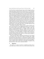
1 Right-click on LWT in the Status bar, pick (left-click)
Settings and:
prompt Lineweight Settings dialogue box
respond 1. ensure Millimeters active
2. scroll at Lineweights and pick 0.4mm
3. dialogue box as Fig. 35.2
4. note the default value then pick OK.
2 Now draw some lines and circles.
3 From the Object Properties toolbar, scroll at lineweight and set to 1.0 then draw some
other lines and circles.
4 Finally set the lineweight back to the default value – 0.25?
5 Figure 35.1 displays some objects at the set lineweights.
Changing properties 237
Figure 35.2 The Lineweight Settings dialogue box.
Beginning with AutoCAD 2002.qxd 14/06/2002 19:07 Page 237
Pickfirst
When objects require to be modified, the normal procedure is to activate the command
then select the objects. This procedure can be reversed with the PICKFIRST system
variable. To demonstrate how this is achieved:
1 Draw a line and circle anywhere on the screen.
2 Menu bar with Modify-Erase and select the two objects then <R>
3 The objects are erased.
4 Draw another line and circle.
5 At the command line enter PICKFIRST <R> and:
prompt Enter new value for PICKFIRST<0>
enter 1 <R>
6 A pickbox will be displayed on the cursor crosshairs. Do not confuse this pickbox with
the grips box. They are different.
7 Pick the line and circle with the pickbox, then menu bar with Modify-Erase. The objects
are erased from the screen.
8 Thus PICKFIRST allows the user to alter the selection process and:
PICKFIRST: 0 – activate the command then select the objects
PICKFIRST: 1 – select the objects then activate the command.
9 We will use PICKFIRST set to 1 to activate the Properties dialogue box.
Changing Properties using the dialogue box
1 With layer OUT current, draw:
a) two concentric circles
b) two lines to represent centre lines.
2 Ensure PICKFIRST is set to 1.
3 With the pick box, select the horizontal line then the PROPERTIES icon from the
Standard toolbar and:
prompt Properties dialogue box
with two tab selections: (a) Alphabetical and (b)Categorized.
4 The dialogue box gives two types of detail:
a) General: layer, colour, linetype, etc.
b) Geometry: start and end point of line, etc.
5 Respond to the dialogue box by:
a) pick Layer line and scroll arrow appears
b) scroll and pick layer CL
c) alter linetype scale value to 0.5 – Fig. 35.3(a)
d) cancel the dialogue box – top right X box
e) press ESC.
6 The selected line will be displayed as a green centre line.
7 Pick the vertical line then the Properties icon and from the Properties dialogue box alter:
a) colour: Magenta
b) linetype: Hidden
c) lineweight: 0.5
d) cancel dialogue box then ESC.
238 Beginning AutoCAD 2002
Beginning with AutoCAD 2002.qxd 14/06/2002 19:07 Page 238
8 Finally pick the smaller circle then the Properties icon and alter:
a) layer: HID
b) linetype scale: 0.75
c) cancel and ESC.
9 Figure 35.1 displays the before and after effects of using the Properties dialogue box to
change objects.
10 Note
a) the Properties dialogue box gives useful information about the objects which are
selected:
1. lines: start and end point; delta values; length; angle
2. circles: centre point; radius; diameter; area; circumference
b) these values can be altered in the dialogue box, and the object will be altered
accordingly. You can try this for yourself.
Changing properties 239
Figure 35.3 The Properties dialogue box for (a) LINE and (b) TEXT.
(a) (b)
Beginning with AutoCAD 2002.qxd 14/06/2002 19:07 Page 239
Changing text
Text has several properties which other objects do not, e.g. style, height, width factor,
etc. as well as layer, linetype and colour. These properties can be altered with the
command line CHANGE (pickfirst: 0) or the Properties dialogue box (pickfirst:1).
To demonstrate how text can be modified using both methods:
1 Create the following text styles:
name STA STB
font romant italict
height 0 12
width 1 1
oblique 0 0
backwards N N
upside-down N Y
vertical N N.
2 With layer TEXT current and STA the current style, enter the text item AutoCAD 2002
at height 5 and rotation 0 at a suitable part of the screen – fig. (A).
3 Multiple copy this item of text to three other parts of the screen.
4 At the command line enter CHANGE <R> and:
prompt Select objects
respond pick the second text item then right-click
prompt Specify change point or [Properties]
respond <RETURN>
prompt Specify new text insertion point <no change>
respond <RETURN> – no change for text start point
prompt Enter new text style <STA>
respond <RETURN> – no change to text style
prompt Specify new height and enter: 3.5 <R>
prompt Specify new rotation angle and enter: 5 <R>
prompt Enter new text <AutoCAD 2002>
enter FIRST CHANGE <R> – fig. (B).
5 With CHANGE <R> at the command line, pick the third item of text and:
a) change point: <R>
b) new text insertion point: <R>
c) new text style: enter STB <R>
d) new rotation angle: –2
e) new text: enter 2nd CHANGE – fig. (C)
f) Question: why no height prompt?
6 With PICKFIRST on (i.e. set to 1) pick the fourth item of text then the Properties icon.
a) The Properties dialogue box will display the following details for the text item:
General; Text; Geometry and Misc.
b) Using the Properties dialogue box alter:
1. text style: STB
2. contents: CAD
3. height: 12
4. width factor: 1.5
5. obliquing: 20
6. Backwards: Yes
c) dialogue box as Fig. 35.3(b)
d) cancel the dialogue box then ESC
e) these changes are displayed in fig. (D).
7 This exercise is now complete and can be saved if required.
240 Beginning AutoCAD 2002
Beginning with AutoCAD 2002.qxd 14/06/2002 19:07 Page 240
Combining ARRAY and CHANGE
Combining the array command with the properties command can give interesting results.
To demonstrate the effect:
1 Open your standard A3PAPER sheet and refer to Fig. 35.4.
2 Draw the two arc segments as trimmed circles using the information given in fig. (a).
3 Draw the polyline and 0 text item using the reference data.
4 With the ARRAY command, polar array (twice) the polyline and text item using an arc
centre as the array centre point:
a) for 4 items, angle to fill +30° with rotation
b) for 7 items, angle to fill –60° with rotation – fig. (b).
5 Using (a)the command line CHANGE or (b) the Properties icon, pick each text item and
alter:
a) the text values to 10, 20, 30 to 90
b) the text height to 8.
6 The final result should be as fig. (c).
7 Save if required as the exercise is complete.
Changing properties 241
Figure 35.4 The combined ARRAY and CHANGE PROPERTIES command.
Beginning with AutoCAD 2002.qxd 14/06/2002 19:07 Page 241
Note
The first exercise demonstrated that it was possible to change the properties of objects
independent of the current layer. This means that if layer OUT (red, continuous) is current,
objects can be created on this layer as green centre lines, blue hidden lines, etc. This is a practice
I would not recommend until you are proficient at using the AutoCAD draughting package.
If green centre lines have to be created, use the correct layer, or make a new layer if required.
Try not to ‘mix’ different types of linetype and different colours on the one layer. Remember
that this is only a recommendation – the choice is always left to the user.
Summary
1 Objects have properties such as colour, layer, linetype, etc.
2 An objects properties can be changed with:
a) the command line CHANGE
b) the Properties dialogue box.
3 To use the Properties dialogue box, the PICKFIRST variable must be set ON, i.e. value 1
4 With PICKFIRST:
a) value 0: select the command then the objects
b) value 1: select the objects then the command.
5 The properties command is very useful when text items are arrayed.
6 Individual objects can have specific linetype scale factors.
242 Beginning AutoCAD 2002
Beginning with AutoCAD 2002.qxd 14/06/2002 19:07 Page 242
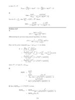
User exercise 3
This exercise will involve creating different arrays with already created text styles.
1 Open C:\BEGIN\STYLEX to display a blank screen but with twelve created and saved text
styles (ST1-ST12) from Chapter 32 – I hope? Refer to Fig. 36.1.
2 With layer OUT current, draw a 30 unit square at A(10,10).
3 Read the note (8) before the next operation.
4 Multiple copy the square from point A to the points B(85,220), C(200,70), D(280,15)
and E(20,255).
5 Array the squares using the following information:
A: rectangular with 2 rows and 5 columns, both distances 35
B: polar for 10 items, full circle with rotation, the centre point of the array being 100,170
C: rectangular with 5 rows and 2 columns and 35 distances
D: angular rectangular (angle of array –10) with 5 rows and 2 columns, the distances
both 35. Remember to rotate first!
E: rectangular for 1 row and 10 columns, the distance 35.
6 Add/or change the text items using the style names listed.
7 Save the completed layout as A:UEREX3.
8 Note
a) text can be added after the squares are arrayed, or before the first square is multiple
copied
b) after array: the text items are added using single line text, the style, rotation angle
and start point being entered by the user. This is fairly straightforward with the
exception of the polar and angular arrays – what are the rotation angles?
c) before the multiple copy: two text items are added to the original square and it is then
multiple copied and arrayed. The added text items can then be altered with the change
properties command
d) it is the user’s preference as to which method is used. I added the text to the original
square, copied, arrayed then changed properties.
Chapter 36
Beginning with AutoCAD 2002.qxd 14/06/2002 19:07 Page 243
Assignments
Two activities have been added which require the array and change properties commands
to be used. Hopefully these activities will give you some relaxation?
1 Activity 31: Telephone dials
The ‘old-fashioned’ type has circles arrayed for a fill angle of ?? Is the text arrayed or
just added to the drawing as text?
You have to decide!
The modern type has a polyline ‘button’ with middled text. The array distances are at
your discretion as is the outline shape.
2 Activity 32: Flow Gauge and Dartboard
a) Flow Gauge: A nice simple drawing to complete, but it takes some time! The text is
added during the array.
b) Dartboard: Draw the circles then array the ‘spokes’. The filled sections are trimmed
donuts. The text is middled, height 10 and ROMANT. Array then change properties?
244 Beginning AutoCAD 2002
Figure 36.1 User exercise 3.
Beginning with AutoCAD 2002.qxd 14/06/2002 19:07 Page 244
Dimension styles 2
In Chapter 20 we investigated how dimensions could be customised to user
requirements by setting and saving a dimension style. The dimension style A3DIM was
created and saved with our A3PAPER standard sheet.
In this chapter we will:
a) create and use several new dimension styles
b) add tolerance dimensions
c) investigate geometric tolerance.
The process for creating new dimension styles involves altering the values for specific
variables which control how the dimensions are displayed on the screen.
Getting started
1 Open your A3PAPER standard drawing sheet.
2 Create the following text styles, all with height 0:
name font
ST1 romans.shx
ST2 scriptc.shx
ST3 italict.shx
ST4 Arial Black.
3 Menu bar with File-Save to update the A3PAPER standard sheet with the four created
text styles. These are then available for future use if required.
4 Now continue with the exercise.
Chapter 37
Beginning with AutoCAD 2002.qxd 14/06/2002 19:07 Page 245
Creating the new dimension styles
1 The A3PAPER standard sheet still on the screen?
2 Menu bar with Dimension-Style and:
prompt Dimension Style Manager dialogue box with style A3DIM
current
respond pick New
prompt Create New Dimension Style dialogue box
with a) New Style Name: Copy of A3DIM
b) Start with: A3DIM
c) Use for: All dimensions
respond 1. alter New Style Name to DIMST1
2. pick Continue
prompt New Dimension Style: DIMST1 dialogue box with tab selections
respond pick OK at present
prompt Dimension Style Manager dialogue box
with Styles: A3DIM and DIMST1
respond pick A3DIM then NEW step(A)
prompt Create New Dimension Style dialogue box as before step(B)
respond 1. alter New Style Name to DIMST2 step(C)
2. pick Continue step(D)
prompt New Dimension Style: DIMST2 dialogue box step(E)
respond pick OK at present step(F)
prompt Dimension Style Manager dialogue box
with Styles: A3DIM, DIMST1 and DIMST2
respond using steps A,B,C,D,E and F, pick A3DIM then New and create new dimension
styles DIMST3, DIMST4, DIMST5 and DIMST6
then when DIMST6 has been created
prompt Dimension Style Manager dialogue box
with Styles: A3DIM, DIMST1 – DIMST6 as Fig. 37.1
respond 1. pick A3DIM then Set Current
2. pick Close.
3 We have now created six new dimension styles (DIMST1 – DIMST6) and these all have
the same ‘settings’ as the A3DIM dimension style.
4 These six new dimension styles have now to be individually modified to meet our
requirements.
246 Beginning AutoCAD 2002
Figure 37.1 The Dimension Style Manager dialogue box with the original A3DIM style and the new
DIMST1–DIMST6 styles.
Beginning with AutoCAD 2002.qxd 14/06/2002 19:08 Page 246
Modifying the new styles
In the exercise which follows, we will only alter certain dimension variables. The rest of
the dimension variables will have the same ‘settings’ as A3DIM.
We will start with DIMST1, so:
1 Menu bar with Dimension-Style and:
prompt Dimension Style Manager dialogue box
respond 1. pick DIMST1
2. pick Modify
prompt Modify Dimension Style: DIMST1 dialogue box with tab selections
respond 1. pick the Text tab
2. Draw frame around text active, i.e. tick
3. Text Placement: Vertical: Centered
Horizontal: Centered
4. Text Alignment: Align with dimension line
5. Text Appearance: Text style: ST1 with height: 4
6. pick OK
prompt Dimension Style Manager dialogue box
respond pick Close
2 The above process is the basic procedure for ‘customising’ dimension styles, the steps being:
a) pick Dimension-Style or the Dimension Style icon
b) pick required style name, e.g. DIMST1
c) pick Modify
d) pick required tab and alter as required
e) pick OK then Close
3 Using the procedure described, alter the named dimension styles to include the following:
Style Tab Alteration
DIMST2 Lines and Arrows Arrowheads: all Box filled
Arrow size: 4
Center Mark Type: Line
Size: 3
Text Appearance Style: ST1 with height: 4
Alignment: Aligned with dimension line
Primary Units Zero suppression
Trailing off: linear and angular
DIMST3 Lines and Arrows Arrowheads: all Oblique, size: 4
Center Mark Type: Mark with size: 4
Text Appearance Style: ST2 with height: 4
Alternative Units Display alternative units active Unit
format: Decimal Precision: 0.00
Multiplier: 0.03937 (default?)
Round distances to: 0
DIMST4 Lines and Arrows Arrowheads: all Dot Small, height: 8
Text Appearance Style: ST1, height: 4
Alignment: Horizontal
Primary Units Measurement scale factor: 2
DIMST5 Text Appearance Style: ST3 with height: 5
Offset from dimension line: 0
DIMST6 Text Appearance Style: ST4 with height: 6
Offset from dimension line: 3
4 When the six dimension styles have been altered, return to the Dimension Style Manager
dialogue box, pick A3DIM-Set Current then Close.
Dimension styles 2 247
Beginning with AutoCAD 2002.qxd 14/06/2002 19:08 Page 247
Using the created dimension styles
1 Using Fig. 37.2 for reference, draw seven horizontal and vertical lines, seven circles and
seven angled lines – the sizes are not of any significance but try and ‘fit’ all the objects
into your drawing ‘frame’.
2 Dimension one set of objects, i.e. a horizontal and vertical line, a circle with diameter
and an angled line. The dimensions added will be with the A3DIM style as fig. (a).
3 Menu bar with Dimension-Style and:
prompt Dimension Style Manager dialogue box
respond 1. pick DIMST1
2. pick Set Current
3. pick Close.
4 Using the set dimension style (DIMST1) dimension another set of four objects.
5 Display the dimension toolbar (View-Toolbars) and note that DIMST1 is displayed,
i.e. it is the current dimension style.
a) pick the scroll arrow to display the other styles – Fig. 37.3
b) pick DIMST2 to make it current
c) cancel or reposition the dimension toolbar
d) dimension a set of objects with the DIMST2 style.
6 At the command line enter –DIMSTYLE <R> and:
prompt Current dimension style: DIMST2
then Enter a dimension style option [Save/Restore
enter R <R> – the restore option
prompt Enter a dimension style name, [?] or <select dimension>
enter DIMST3 <R>
and DIMST3 displayed in Dimension toolbar if displayed
note if the text window appears, cancel it.
7 Dimension a set of objects with the DIMST3 style.
8 Using the menu bar selection Dimension-Style, the Dimension toolbar or the command
line –DIMSTYLE entry:
a) make each created dimension style current
b) dimension a set of objects with each style.
9 Figure 37.2 displays the result of the exercise which can be saved if required.
248 Beginning AutoCAD 2002
Beginning with AutoCAD 2002.qxd 14/06/2002 19:08 Page 248
Dimension styles 2 249
Figure 37.2 The dimension styles exercise.
Figure 37.3 The Dimension toolbar with created styles.
Beginning with AutoCAD 2002.qxd 14/06/2002 19:08 Page 249
Comparing dimension styles
It is possible to compare dimension styles with each other and note any changes between
them.
1 Menu bar with Dimension Style and:
prompt Dimension Style Manager dialogue box
respond pick DIMST4 then Compare
prompt Compare Dimension Styles dialogue box
with Compare: DIMST4
respond scroll and alter With name to A3DIM – Fig. 37.4
prompt Compare Dimension Styles dialogue box with a comparison between
the different dimension variables of DIMST4 and A3DIM
respond note the differences then Close both dialogue boxes.
250 Beginning AutoCAD 2002
Figure 37.4 The Compare Dimension Styles dialogue box.
Beginning with AutoCAD 2002.qxd 14/06/2002 19:08 Page 250
Dimension variables
The above comparison between the two dimension styles displays some of the AutoCAD
dimension variables. All dimension variables (dimvars) can be altered by keyboard entry.
To demonstrate this:
1 Make DIMST1 the current dimension style and note the dimensions which used this
style – the second set of dimensioned objects.
2 At the command line enter DIMASZ <R> and:
prompt Enter new value for DIMASZ <3.50>
enter 8 <R>
3 Pick the Dimension Style icon from the Dimension toolbar and:
prompt Dimension Style Manager dialogue box
with a) Current Style: DIMST1
b) DIMST1
|
_____
<style overrides>
c) Description: DIMST1+Arrow size=8.00 – Fig. 38.5
(i.e. DIMST1 has been altered)
respond 1. move pointer over <style overrides>
2. right-click the mouse
prompt Shortcut menu displayed
respond 1 pick Save to current style
2 pick Close.
4 The dimensions which used the DIMST1 dimension style will be displayed with an arrow
size of 8.
5 Now change the DIMASZ variable for DIMST1 back to 3.5.
6 This exercise is now complete and can be saved if required.
Dimension styles 2 251
Figure 37.5 The Dimension Style Manager dialogue box with the DIMST1 overrides.
Beginning with AutoCAD 2002.qxd 14/06/2002 19:08 Page 251
Task
1 Open your A3PAPER standard sheet with the four saved text styles ST1–ST4
2 Using the Dimension Style Manager dialogue box:
a) check current style is A3DIM
b) with Modify-Text tab, set the text style to ST1 with height 4
c) pick OK then close the dialogue box
3 Menu bar with File-Save to update the A3PAPER standard sheet with the modified
A3DIM dimension style.
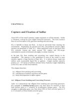
Tolerance dimensions
Dimensions can be displayed with tolerances and limits, the ‘types’ available being
symmetrical, deviation, limits and basic. These are displayed in Fig. 37.6(a) with the
standard default dimension type, i.e. no tolerances displayed. To use tolerance
dimensions correctly, a dimension style should be created for each ‘type’ which is to be
used in the drawing. As usual we will investigate the topic with an exercise so:
1 Open your A3PAPER standard sheet and refer to Fig. 37.6.
2 Draw a line, circle and angled line and copy them to four other areas of the screen.
3 Dimension one set of objects with your standard A3DIM dimension style setting
– fig. (p).
252 Beginning AutoCAD 2002
Figure 37.6 Dimension tolerance exercise.
Beginning with AutoCAD 2002.qxd 14/06/2002 19:08 Page 252
Creating the tolerance dimension styles
1 Using the Dimension Style Manager dialogue box, create four new named dimension
styles, all starting with A3DIM. The four new style names are DIMTOL1, DIMTOL2,
DIMTOL3 and DIMTOL4.
2 With the Dimension Style Manager dialogue box:
a) pick each new dimension style
b) pick Modify then select the:
1. Primary Units tab and alter both the Linear and Angular precision to 0.000
2. Tolerances tab and alter as follows:
DIMTOL1 DIMTOL2 DIMTOL3 DIMTOL4
Method Symmetrical Deviation Limits Basic
Precision 0.000 0.000 0.000
Upper value 0.007 0.007 0.007
Lower value 0.003 0.003
Scaling for height 1 1 1
Vertical position Middle Middle Middle Middle
3 Making each new dimension style current, dimension a set of three objects. The effect
is displayed in Fig. 37.6 with:
fig. (q) : style DIMTOL1 fig. (r) : style DIMTOL2
fig. (s) : style DIMTOL3 fig. (t) : style DINTOL4
4 Task
Investigate the vertical position and the scaling for height options available in the
Tolerances tab dialogue box. Figure 37.6 displays the following:
fig. method vertical pos scaling for height
w deviation top 0.8
x deviation bottom 0.8
y symmetrical top 0.7
z symmetrical bottom 0.7
5 This exercise is complete and can now be saved.
Dimension styles 2 253
Beginning with AutoCAD 2002.qxd 14/06/2002 19:08 Page 253
Geometric tolerancing
AutoCAD 2002 has geometric tolerancing facilities and to demonstrate this feature:
1 Open your A3PAPER standard sheet.
2 Menu bar with Dimension-Tolerance and:
prompt Geometric Tolerance dialogue box
with Feature Control Frames
respond move pointer to box under Sym and right-click
prompt Symbol dialogue box as Fig. 37.7
respond 1. press ESC to cancel the Symbol dialogue box
2. study the Geometric Tolerance dialogue box
3. pick Cancel at present.
Feature control frames
Geometric tolerances define the variations which are permitted to the form or profile of
a component, its orientation and location as well as the allowable runout from the exact
geometry of a feature. Geometric tolerances are added by the user in feature control
frames, these being displayed in the Geometric Tolerances dialogue box. A feature
control frame consists of two/three sections or compartments. These are displayed in
Fig. 37.8(a) and are:
A) The geometric characteristic symbol
This is a symbol for the tolerance which is to be applied. These geometric symbols
can represent location, orientation, form, profile and runout. The symbols include
symmetry, flatness, straightness, angularity, concentricity, etc.
B) The tolerance section (1 and 2)
This creates the tolerance value in the Feature Control Frame. The tolerance indicates
the amount by which the geometric tolerance characteristic can deviate from a perfect
form. It consist of three boxes:
a) first box: inserts an optional diameter symbol
b) second box: the actual tolerance value
c) third box: displays the material code which can be:
1. M : at maximum material condition
2. L : at least material condition
3. S : regardless of feature size
C) The primary, secondary and tertiary datum information
This can consist of the reference latter and the material code. Typical types of
geometric tolerance ‘values’ are displayed in Fig. 37.8(b).
254 Beginning AutoCAD 2002
Figure 37.7 The Symbol dialogue box.
Beginning with AutoCAD 2002.qxd 14/06/2002 19:08 Page 254
Note
a) Feature control frames are added to a dimension by the user.
b) A feature control frame contains all the tolerance information for a single dimension.
The tolerance information must be entered by the user.
c) Feature control frames can be copied, moved, erased, stretched, scaled and rotated
once ‘inserted’ into a drawing.
d) Feature control frames can be modified with DDEDIT.
Dimension styles 2 255
Figure 37.8 Geometric tolerance terminolgy and usage.
Beginning with AutoCAD 2002.qxd 14/06/2002 19:08 Page 255
Geometric tolerance example
1 Refer to Fig. 37.8(c) and create a square with circles as shown. The size and layout is of
no importance.
2 Diameter dimension the larger circle using the A3DIM dimension style (should be
current) and the DIMS layer.
3 Select the TOLERANCE icon from the Dimension toolbar and:
prompt Geometric Tolerance dialogue box
respond pick top box under Sym
prompt Symbol dialogue box
respond pick Concentricity symbol (2nd top left)
prompt Geometric Tolerance dialogue box
with Concentricity symbol displayed
respond 1. at Tolerance 1, pick left box
2. at Tolerance 1, enter 0.03
3. at Tolerance 1, pick MC box and:
prompt Material Condition dialogue box
respond pick M
4. at Datum 1, enter A
5. at Datum 1, pick MC box, pick M
6. Geometric Tolerance dialogue box as Fig. 37.9
then pick OK
prompt Enter tolerance location
respond pick ‘under’ the diameter dimension.
4 Menu bar with Dimension-Tolerance and:
prompt Geometric Tolerance dialogue box
respond pick top Sym box
prompt Symbol dialogue box
respond pick Position symbol (top left)
prompt Geometric Tolerance dialogue box
respond 1. at Tolerance 1 pick left box (for diameter symbol)
2. at Tolerance 1 enter value of 0.1
3. at Tolerance 1 pick MC box and pick M
4. at Datum 1 enter datum A
5. at Datum 1 pick MC box and pick M
6. pick OK
prompt Enter tolerance location
respond pick to suit – refer to Fig. 37.8(c).
5 Select the LEADER icon from the Dimension toolbar and:
prompt Specify first leader point and pick a smaller circle
prompt Specify next point and pick a point to suit then right-click
prompt Specify text width and enter: 0 <R>
prompt Enter first line of annotation text and right-click
prompt Multiline Text Editor dialogue box
enter 4 holes diameter 6.45 plus/minus 0.05 (use symbols)
then pick OK.
256 Beginning AutoCAD 2002
Beginning with AutoCAD 2002.qxd 16/06/2002 11:43 Page 256
Geometric tolerance exercise
1 Refer to Fig. 37.8(d) and create ‘shapes’ as shown – size is not important.
2 Add the geometric tolerance information.
3 Investigate the height, projected tolerance zone and datum identifier options from the
Geometric Tolerance dialogue box as fig. (e).
Summary
1 Dimension styles are created by the user and ‘customized’ for company/customer
requirements.
2 Dimension styles are created with the Dimension Style Manager dialogue box using
several tab selections.
3 It possible to alter dimension variables (dimvars) from the command line.
4 Tolerance dimensions can be created as dimension styles. The four ‘types’ are
symmetrical, deviation, limits and basic.
5 Geometric tolerances can be added to drawings using feature control frames.
6 There are 14 geometric tolerance ‘types’ available.
7 All geometric tolerance information must be added by the user in feature control frames.
8 Feature control frames can be copied, moved, scaled, etc.
Assignments
Two assignments on dimension styles, tolerance dimensions and geometric tolerancing.
Adding dimensions to a drawing is generally a tedious process and if dimension styles
and geometric tolerancing are required, the process does not get any easier.
1 Activity 33: Tolerance dimensions
The two drawings are easy to complete.
Adding the dimensions requires four created styles, all from the A3DIM default. The
dimension styles use the symmetrical, limits, deviation and basic tolerance methods. You
have the enter the upper and lower values.
2 Activity 34: Geometric tolerances.
A slightly more complex drawing to complete.
Several dimension styles have to be created and two geometric tolerances have to be added.
Dimension styles 2 257
Figure 37.9 The Geometric Tolerance dialogue box.
Beginning with AutoCAD 2002.qxd 14/06/2002 19:08 Page 257