Beginning AutoCAD 2002 Episode 8 pps
Bạn đang xem bản rút gọn của tài liệu. Xem và tải ngay bản đầy đủ của tài liệu tại đây (1.21 MB, 30 trang )
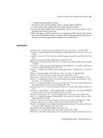
Stretch example
1 Open your WORKDRG and refer to Fig. 30.2
2 a) erase the centre lines
b) add hatching – own selection
c) linear dimension the two lines with menu bar selection
3 Activate the STRETCH command and:
a) enter C <R> – crossing option
b) first corner: pick a point P1
c) opposite corner: pick a point P2 then right-click
d) base point: pick any suitable point
e) second point: enter @15,0 <R>
4 Repeat the STRETCH command and:
a) activate the crossing option
b) pick a point P3 for the first corner
c) pick a point P4 for the opposite corner
d) pick a suitable base point
e) enter @0,–15 as the second point
5 The component and dimensions will be stretched with the entered values.
Lengthen, align and stretch 203
Figure 30.2 Using the STRETCH command.
Beginning with AutoCAD 2002.qxd 14/06/2002 19:07 Page 203
Stretch activity
Refer to Fig. 30.2 and:
1 Draw the original component as shown adding the four dimensions.
2 Using the STRETCH command only, produce the modified component.
3 There is no need to save this activity.
Summary
1 Lengthen will increase/decrease the length of lines, arcs and polylines. There are several
options available.
2 Dimensions are not lengthened with the command.
3 Align is a powerful command which combines move and rotate into one operation. The
order of selecting points is important.
4 Stretch can be used with lines, polylines and arcs. It does not affect circles.
5 Dimensions and hatching are stretched due to association.
204 Beginning AutoCAD 2002
Beginning with AutoCAD 2002.qxd 14/06/2002 19:07 Page 204
Obtaining information
from a drawing
Drawings contain information which may be useful to the user, e.g. coordinate data,
distances between points, area of shapes, etc. We will investigate how this information
can be obtained, so:
1 Open C:\BEGIN\USEREX and refer to Fig. 31.1.
2 Draw a circle, centre at: 190,140 and radius: 30.
3 Activate the Inquiry toolbar.
Chapter 31
Figure 31.1 Obtaining drawing information.
Beginning with AutoCAD 2002.qxd 14/06/2002 19:07 Page 205
Point identification
This command displays the coordinates of a selected point.
1 Select the LOCATE POINT icon from the Inquiry toolbar and:
prompt Specify point
respond Snap to Midpoint icon and pick line 23.
2 The command line area displays:
X = 240.00 Y = 150.00 Z = 0.00.
3 Menu bar with Tools-Inquiry-ID Point and:
prompt Specify point
respond Snap to Center icon and pick the circle.
4 Command line display is X = 190.00 Y = 140.00 Z = 0.00.
5 The command can be activated with ID <R> at the command line.
Distance
Returns information about a line between two selected points including the distance and
the angle to the horizontal.
1 Select the DISTANCE icon from the Inquiry toolbar and:
prompt Specify first point
respond pick point 8 (snap to endpoint or intersection)
prompt Specify second point
respond pick point 2.
2 The command prompt area will display:
Distance=141.42, Angle in XY plane=45.0, Angle from XY plane=0.0
Delta X=100.00, Delta Y=100.00, Delta Z=0.00.
3 Menu bar with Tools-Inquiry-Distance and:
prompt Specify first point
respond snap to centre of circle
prompt Specify second point
respond pick midpoint of line 23.
4 The display at the command prompt is:
Distance=50.99, Angle in XY plane=11.3, Angle from XY plane=0.0
Delta X=50.00, Delta Y=10.00, Delta Z=0.00.
5 Using the DISTANCE command, select point 2 as the first point and point 8 as the second
point. Is the displayed information any different from step 1?
6 Entering DIST <R> at the command line will activate the command.
206 Beginning AutoCAD 2002
Beginning with AutoCAD 2002.qxd 14/06/2002 19:07 Page 206
List
A command which gives useful information about a selected object.
1 Select the LIST icon from the Inquiry toolbar and:
prompt Select objects
respond pick the circle then right-click
prompt AutoCAD Text Window with information about the circle.
respond F2 to flip back to drawing screen.
2 Menu bar with Tools-Inquiry-List and:
prompt Select objects
respond pick line 12 then right-click
prompt AutoCAD text window
either a) F2 to flip back to drawing screen
or b) cancel icon from text window title bar.
3 Figure 31.2 is a screen dump of the AutoCAD Text window display for the two selected
objects.
4 LIST <R> is the command line entry.
Obtaining information from a drawing 207
Figure 31.2 The AutoCAD Text Window.
Beginning with AutoCAD 2002.qxd 14/06/2002 19:07 Page 207
Area
This command will return the area and perimeter for selected shapes or polyline shapes.
It has the facility to allow composite shapes to be selected.
1 Select the AREA icon from the Inquiry toolbar and:
prompt Specify first corner point or [Object/Add/Subtract]
enter O <R> – the object option
prompt Select objects
respond pick the circle.
2 The command line will display:
Area=2827.43, Circumference=188.50.
3 Question: are these values the same as from the LIST command?
4 Menu bar with Tools-Inquiry-Area and:
prompt Specify first corner point or [Object/Add/Subtract]
respond Snap to endpoint and pick point 1
prompt Specify next corner point or press ENTER for total
respond Snap to endpoint and pick point 2
prompt Specify next corner point or
respond Snap to endpoint and pick points 3,4,5,6,7,8
prompt Specify next corner point or press ENTER for total
respond press <RETURN>.
5 Command line displays:
Area=11500.00, Perimeter=450.00.
6 Question: Are these figures correct for the shape selected?
7 At the command line enter AREA <R> and:
prompt Specify first corner point or [Object/Add/Subtract]
enter A <R> – the add option
prompt Specify first corner point or [Object/Subtract]
respond Endpoint icon and pick point 1
prompt Specify next corner point or press ENTER for total (ADD
mode)
respond Endpoint icon and pick point 2
prompt Specify next corner point or press ENTER for total (ADD
mode)
respond Endpoint icon and pick points 3,4,5,6,7,8
prompt Specify next corner point or press ENTER for total (ADD
mode)
respond press <RETURN>
prompt Area=11500.00, Perimeter: 450.00
Total area=11500.00
then Specify first corner point or [Object/Subtract]
enter S <R> – the subtract option
prompt Specify first corner point or [Object/Add]
enter O <R> – the object option
prompt (SUBTRACT mode) Select objects
respond pick the circle
prompt Area: 2827.43, Circumference: 188.50
Total area=8672.57
then (SUBTRACT mode) Select objects
respond ESC to end command.
8 Question: Is the area value of 8672.57 correct for the outline area less the circle area?
208 Beginning AutoCAD 2002
Beginning with AutoCAD 2002.qxd 14/06/2002 19:07 Page 208
Time
This command displays information in the AutoCAD Text Window about the current
drawing, e.g.:
a) when it was originally created
b) when it was last updated
c) the length of time worked on it.
1 The command can be activated:
a) from the menu bar with Tools-Inquiry-Time
b) by entering TIME <R> at the command line.
2 The command has options of Display, On, Off and Reset.
3 A useful command for your boss?
Status
This command gives additional information about the current drawing as well as disk
space information. Select the sequence Tools-Inquiry-Status to ‘see’ the status display
in the AutoCAD text window.
Calculator
1 AutoCAD 2002 has a built-in calculator which can be used:
a) to evaluate mathematical expressions
b) to assist on the calculation of coordinate point data.
2 The mathematical operations obey the usual order of preference with brackets, powers, etc.
3 At the command line enter CAL <R> and:
prompt Initializing >> Expression:
enter 12.6*(8.2+5.1) <R>
prompt 167.58 – is it correct?
4 Enter CAL <R> and:
prompt >>Expression:
enter (5*(7-4))^3.5 <R>
prompt 13071.3.
5 Question:
What is answer to ((7 − 4)+(2 ∗ (8+1))) – a key question?
Transparent calculator
A transparent command is one which can be used ‘while in another command’ and is
activated from the command line by entering the ‘ symbol. The calculator command has
this transparent ability.
1 Activate the DONUT command and set diameters of 0 and 3, then:
prompt Specify center of donut
enter ‘CAL <R> – the transparent calculator command
prompt >>Expression:
enter CEN/2 <R>
prompt >>Select entity for CEN snap
respond pick the circle
prompt (95.0 70.0 0.0)
Obtaining information from a drawing 209
Beginning with AutoCAD 2002.qxd 14/06/2002 19:07 Page 209
and donut at position A
prompt Specify center of donut
enter ‘CAL <R>
prompt >>Expression:
enter (MID+INT) <R>
prompt >>Select entity for MID snap and: pick line 65
prompt >>Select entity for INT snap and: pick point 8
prompt (330.0 175.0 0.0)
and donut at position B
prompt Specify center of donut and right-click.
2 Activate the circle command and:
prompt Specify center point for circle and enter 55,45 <R>
prompt Specify radius of circle
enter ‘CAL <R>
prompt >>Expression:
enter rad/2 <R>
prompt >>Select circle, arc or polyline segment for RAD function
respond pick the original circle
and circle at position C.
3 Check the donut centre points with the ID command. They should be (a)95,70 and
(b)330,175. These values were given at the command prompt line as the donuts were
being positioned.
Task
1 Refer to Fig. 31.1 and create the following (anywhere on the screen, but use SNAP ON
to help):
a) right-angled triangle with: vertical side of 50 and horizontal side of 60
b) square of side 80 and inside this square: two other squares of side 15 and 20
c) circles: radii 23 and 37 – concentric
d) polyshape: to size given, offset 15 ‘inwards’
2 Find the shaded areas using the AREA command.
3 Obtain the areas of the three ‘vertical strips’ of the original USEREX, i.e. without the
circle.
Summary
1 Drawings can be ‘interrogated’ to obtain information about:
a) coordinate details
b) distance between points
c) area and perimeter of composite shapes
d) the status and time for the current drawing
2 AutoCAD has a built-in calculator which can be used transparently
210 Beginning AutoCAD 2002
Beginning with AutoCAD 2002.qxd 14/06/2002 19:07 Page 210
Text fonts and styles
Text has been added to previous drawings without any discussion about the ‘appear-
ance’ of the text items. In this chapter we will investigate:
a) text fonts and text styles
b) text control codes.
The words ‘font’ and ‘style’ are extensively used with text and they can be explained as:
Font: defines the pattern which is used to draw characters, i.e. it is basically an
alphabet ‘appearance’. AutoCAD 2002 has over 90 fonts available to the user,
and Fig. 32.1 displays the text item ‘AutoCAD 2002’ using 30 of these fonts.
Style: defines the parameters used to draw the actual text characters, i.e. the width
of the characters, the obliquing angle, whether the text is upside-down,
backwards, etc.
Chapter 32
Figure 32.1 Some of AutoCAD 2002’s text fonts, all at height 8.
Beginning with AutoCAD 2002.qxd 14/06/2002 19:07 Page 211
Notes
1 Text fonts are ‘part of’ the AutoCAD package.
2 Text styles are created by the user.
3 Any text font can be used for many different styles.
4 A text style uses only one font.
5 If text fonts are to be used in a drawing, a text style must be created by the user.
6 New text fonts can be created by the user, but this is outside the scope of this book.
7 Text styles can be created
a) by keyboard entry
b) via a dialogue box.
Getting started
1 Open A:A3PAPER with layer TEXT current.
2 At the command line enter -STYLE <R> and
prompt Enter name of text style or [?]<Standard>
enter ? <R> – the ‘query’ option
prompt Enter text style(s) to list<*>
enter <R>
prompt AutoCAD Text Window
with Style name: “Standard” Font files: txt
Height: 0.00 Width Factor: 1.00 Obliquing angle: 0.0
Generation: Normal.
3 This is AutoCAD 2002’s ‘default’ text style. It has the text style name STANDARD and
uses the text font txt. Realise that your system may have a different text style name
and font. If it does, do not worry. It will not affect our exercise.
4 Cancel the text window.
5 With the menu bar sequence Draw-Text-Single Line Text, add the text item
AutoCAD 2002 at 110,275 with height 8 and rotation angle 0.
6 The step 2 entry of –STYLE was to allow us to use the command line instead of a
dialogue box. I thought that it would be easier to understand from the command line.
Creating a text style from the keyboard
1 At the command line enter –STYLE <R> and:
prompt Enter name of text style or [?]
enter ST1 <R> – the style name
prompt Specify full font name or font filename (TTF or SHX)
enter romans.shx <R>
prompt Specify height of text and enter: 0 <R>
prompt Specify width factor and enter: 1 <R>
prompt Specify obliquing angle and enter: 0 <R>
prompt Display text backwards? and enter: N <R>
prompt Display text upside-down? And enter: N <R>
prompt Vertical? and enter: N <R>
prompt “st1” is now the current style.
2 The above entries of height, width factor, etc. are the parameters which must be defined
for every text style created.
212 Beginning AutoCAD 2002
Beginning with AutoCAD 2002.qxd 14/06/2002 19:07 Page 212
Creating a text style from a dialogue box
1 From the menu bar select Format-Text Style and
prompt Text Style dialogue box
with 1. ST1 as the Style Name
2. romans.shx as the Font Name
3. Height: 0.0
respond pick New and:
prompt New Text Style dialogue box
respond 1. alter Style Name to ST2
2. pick OK
prompt Text Style dialogue box
with ST2 as the Style Name
respond 1. pick the scroll arrow at right of romans.shx
2. scroll and pick italict.shx
3. ensure that:
Height: 0.00, Width Factor: 1.00, Oblique Angle: 0.0
4. note the Preview box
5. dialogue box as Fig. 32.2
6. pick Apply then Close.
2 With the menu bar selection Format-Text Style, use the Text Style dialogue box as step
1 to create the following new text styles:
Effects
Style Font Width Obl’g Back- Upside
name name Ht factor angle wards down Vert’l
ST3 gothice.shx 12 1 0 OFF OFF OFF
ST4 Arial Black 10 1 0 OFF OFF OFF
ST5 italict.shx 5 1 30 OFF OFF OFF
ST6 Romantic 10 1 0 OFF ON –––
ST7 scriptc.shx 5 1 –30 OFF OFF OFF
ST8 monotxt.shx 6 1 0 OFF OFF ON
ST9 Swis721BdOulBT 12 1 0 OFF OFF OFF
ST10 complex.shx 5 1 0 ON OFF OFF
ST11 isoct.shx 5 1 0 ON ON –––
ST12 romand.shx 5 1 0 ON ON ON
3 Note: when using the Text Style dialogue box, a TICK in a box means that the effect is
on, a blank box means that the effect is off.
Text font and styles 213
Figure 32.2 The Text Style dialogue box for the ST2 new test style.
Beginning with AutoCAD 2002.qxd 14/06/2002 19:07 Page 213
Using created text styles
1 Menu bar with Draw-Text-Single Line Text and
prompt Specify start point of text or [Justify/Style]
enter S <R> – the style option
prompt Enter style name (or ?) – ST12 as default name?
enter ST1 <R>
prompt Specify start point of text or [Justify/Style]
enter 20,240 <R>
prompt Specify height and enter: 8 <R>
prompt Specify rotation angle of text and enter: 0 <R>
prompt Enter text and enter: AutoCAD 2002 <R>
2 Using the single line text command, add the text item AutoCAD 2002 using the following
information:
Style Start pt Ht Rot
ST1 20,260 8 0 – already entered
ST2 225,265 8 0
ST3 15,145 NA 0
ST4 250,240 NA 0
ST5 25,175 NA 30
ST6 100,220 NA 0
ST7 145,195 NA –30
ST8 215,235 NA 270 (default angle)
ST9 235,195 NA 0
ST10 365,165 NA 0
ST11 325,145 NA 0
ST12 400,140 NA 270 (default angle)
3 When completed, the screen should display 13 different text styles – the 12 created and
the STANDARD default as Fig. 32.3.
4 There is no need to save this drawing but:
a) erase all the text from the screen
b) save the ‘blank’ screen as C:\BEGIN\STYLEX – you are really saving the created text
styles for future use.
Notes
Text styles and fonts can be confusing to new AutoCAD users due to the terminology,
and by referring to Fig. 32.3, the following may be of assistance:
1 Effects:
Three text style effects which can be ‘set’ are upside-down, vertical and backwards. These
effects should be obvious to the user, and several of our created styles had these effects
toggled on.
2 Width factor:
A parameter which ‘stretches’ the text characters and fig. (a) displays an item of text
with six width factors. The default width factor value is 1.
3 Obliquing angle:
This parameter ‘slopes’ the text characters as is apparent in fig. (b) and the default
value is 0.
214 Beginning AutoCAD 2002
Beginning with AutoCAD 2002.qxd 14/06/2002 19:07 Page 214
4 Height:
When the text command was used with the created text styles, only two styles prompted
for a height – ST1 and ST2. The other text styles had a height value entered when the
style was created – hence no height prompt. This also means that these text styles cannot
be used at varying height values. The effect of differing height values is displayed in
fig. (c).
5 Recommendation:
I would strongly recommend that if text styles are being created, the height be left
at 0. This will allow you to enter any text height at the prompt when the text command
is used.
6 The text items displayed using styles ST5 and ST7 are interesting, these items having:
ST5 30 obliquing 30 rotation
ST7 –30 obliquing –30 rotation
These styles give an ‘isometric text’ appearance.
Text font and styles 215
Figure 32.3 Using the created text styles.
Beginning with AutoCAD 2002.qxd 14/06/2002 19:07 Page 215
Text control codes
When text is being added to a drawing, it may be necessary to underline the text item,
or add a diameter/degree symbol. AutoCAD has several control codes which when used
with the Single Line Text command will allow underscoring, overscoring and symbol
insertion.
The available control codes are:
%%O: toggles the OVERSCORE on/off
%%U: toggles the UNDERSCORE on/off
%%D: draws the DEGREE symbol for angle or temperature (°)
%%C: draws the DIAMETER symbol (∅)
%%P: draws the PLUS/MINUS symbol (±)
%%%: draws the PERCENTAGE symbol (%)
1 Open C:\BEGIN\STYLEX with the 12 created text styles.
2 Refer to Fig. 32.4, select Draw-Text-Single Line Text and:
prompt Specify start point of text or [Justify/Style]
enter S <R>
prompt Enter style name or [?]
enter ST1 <R>
prompt Specify start point of text and enter: 25,250 <R>
prompt Specify height and enter: 10 <R>
prompt Specify rotation angle of text and enter: –5 <R>
prompt Enter text and enter %%UAutoCAD 2002%%U <R>
prompt Enter text and <R>
3 At the command line enter DTEXT <R> and:
a) style: ST3
b) start point: 175,255
c) angle: 0
d) text: 123.45%%DF.
4 Activate the single line text command and:
a) style: ST4
b) start point: 35,175
c) angle: 0
d) text: %%UUNDERSCORE%%U and %%OOVERSCORE%%O.
5 With the single line text command
a) style: ST9
b) start point: 285,215
c) angle: 0
d) text: %%C100.
6 Refer to Fig. 32.4 and add the other text items – or text items of your choice. The text
style used is at your discretion.
7 Save if required, but we will not use this drawing again.
216 Beginning AutoCAD 2002
Beginning with AutoCAD 2002.qxd 14/06/2002 19:07 Page 216
Summary
1 Fonts define the pattern of characters.
2 Styles define the parameters for drawing characters.
3 Text styles must be created by the user.
4 A font can be used for several text styles.
5 Every text style must use a text font.
6 The AutoCAD 2002 default text style is called STANDARD and uses the text font txt.
7 Text control codes allow under/overscoring and symbols to be added to text items.
8 No mention has been made of the different types of font extension used with AutoCAD.
This is considered beyond the scope of this book.
Text font and styles 217
Figure 32.4 Text control codes.
Beginning with AutoCAD 2002.qxd 14/06/2002 19:07 Page 217
Multiline text
Multiline text was referred to as paragraph text in previous releases. It is a useful
draughting tool as it allows large amounts of text to be added to a pre-determined area
on the screen. This added text can also be edited.
1 Open the STYLEX with the created text styles.
2 Display toolbars to suit, including the TEXT toolbar.
3 With layer TEXT current, select the TEXT from the Draw toolbar and:
prompt Specify first corner
enter 10,275 <R>
prompt Specify opposite corner or [Height/Justify/Line spacing/
Rotation/Style/Width]
enter S <R> then ST1 <R> – setting the text style
prompt Specify opposite corner or [Height/Justify/Line spacing/
Rotation/Style/Width]
enter H <R> then 5 <R> – setting the height
prompt Specify opposite corner or [Height/Justify/Line spacing/
Rotation/Style/Width]
enter 125,190 <R>
prompt Multiline Text Editor dialogue box
with flashing cursor in the ‘window area’
respond 1. enter the following text including the typing errors which have been
underlined
2. do not try to add the underline effect
3. do not press the return key
enter CAD is a draughting tol with many benefits when compared to conventional
draughting techniches. Some of these benefitds include incresed productivity,
shorter lead tines, standardisation, acuracy amd rapid resonse to change.
and dialogue box as Fig. 33.1
respond pick OK.
4 The entered text is displayed as Fig. 33.2(a).
5 Notes:
a) the text ‘wraps around’ the Text Editor window as it is entered from the keyboard
b) the text is fitted into the width of the selected area of the screen, not the full
rectangular area of the dialogue box
c) the width is determined by the entered coordinates
d) the entered text in the dialogue box will not appear as the above layout. This is normal,
so don’t worry about it.
Chapter 33
Beginning with AutoCAD 2002.qxd 14/06/2002 19:07 Page 218
Multiline text 219
Figure 33.1 The Multiline Text Editor dialogue box with the item of text to be entered.
Figure 33.2 Multiline text exercise.
Beginning with AutoCAD 2002.qxd 14/06/2002 19:07 Page 219
Spellcheck
AutoCAD 2002 has a built-in spellchecker which has been used in an earlier chapter. It
can be activated:
a) from the menu bar with Tools-Spelling
b) by entering SPELL <R> at the command line
1 Activate the spell check command and:
prompt Select objects
respond pick any part of the entered text then right-click
prompt Check Spelling dialogue box
with 1. current dictionary: British English (ise)
2. current word: probably draughting
3. suggestions: probably draughtiness
4. context: CAD is a draughting tol
respond pick Ignore All
note we have agreed that draughting is correct spelling
prompt Check Spelling dialogue box
with 1. current word: tol
2. suggestions: toll, tool, to
respond 1. pick tool – becomes highlighted
2. tool added to Suggestion box
3. dialogue box as Fig. 33.3
4. pick Change
prompt Check Spelling dialogue box
with 1. current word: techniches
2. suggestions: tech
respond 1. at suggestions, alter tech to techniques
2. pick Change
prompt Check Spelling dialogue box
respond change the following as they appear:
original alter to
benefitds benefits
incresed increased
acuracy accuracy
amd and (manual change required)
resonse response
then AutoCAD Message
Spelling check complete
respond pick OK.
2 The multiline text will be displayed with the correct spelling as Fig. 33.2(b).
3 One of the original spelling mistakes was ‘tines’ (times) and this was not highlighted
with the spellcheck. This means that the word ‘tines’ is a ‘real word’ as far as the
dictionary used is concerned although it is wrong to us. This can be a major problem
with spellchecks.
4 Enter DDEDIT <R> at the command line and:
a) pick any part of the text
b) the Multiline Text Editor dialogue box will be displayed and the word tines can be
altered to times.
c) when the alteration is complete, pick OK.
5 Multiple copy the corrected text to seven other places on the screen and refer to Fig. 33.2.
220 Beginning AutoCAD 2002
Beginning with AutoCAD 2002.qxd 14/06/2002 19:07 Page 220
Editing multiline text
1 Select the EDIT TEXT icon from the Text toolbar and:
prompt Select an annotation object or [Undo]
respond pick a copied multiline text item
prompt Multiline Text Editor dialogue box
with text displayed
respond 1. left-click and drag mouse over CAD
2. alter height to 7 then pick OK
3. right-click-Enter to end command
4. text displayed as fig. (c).
2 Menu bar with Modify-Object-Text-Edit and:
prompt Select an annotation object
respond pick copied text item
prompt Multiline Text Editor dialogue box
respond 1. pick Properties tab
2. scroll at Style, pick ST5 then pick OK
3. right-click-Enter – fig. (d).
3 Using the Edit Text command alter the other copied multiline text items using the
following information:
a) Properties: Justification to Top Right – fig. (e)
b) Properties: Rotation to –5 – fig. (f)
c) Properties: Width to 120 – fig. (g)
d) Properties: Style to ST7
Justification to Top Centre – fig. (h)
e) underline lead times and alter height to 8 – fig. (i).
4 This exercise is now complete and can be saved if required.
Multiline text 221
Figure 33.3 The Check Spelling dialogue box.
Beginning with AutoCAD 2002.qxd 14/06/2002 19:07 Page 221
Text modifications
To investigate some of the other text modifications, erase all the multilane text items
except the TR justification – fig. (e). Move this item of text to the top left of the screen
and refer to Fig. 33.4.
1 Select the Find and Replace icon from the Text toolbar and:
prompt Find and Replace dialogue box
respond 1. Find text string: enter CAD
2. Replace with: Computer Aided Draughting
3. Search in: Entire drawing
4. pick Find
prompt Context will display text with CAD highlighted
respond pick Replace
prompt No more occurrences found – Fig. 33.5
respond pick Close.
3 The text item will be displayed with CAD replaced by Computer Aided Draughting – fig. (b).
4 Multiple copy this replace multiline text item to three other parts of the screen.
5 With the single line text icon from the text toolbar, create an item of text using:
a) style: ST2
b) start point: pick to suit
c) height: 3.75
d) rotation angle: 5
e) text: TEST.
6 Select the Scale Text icon from the Text toolbar and:
prompt Select objects
respond pick a copied multiline text item then right-click
prompt Enter a base point option for scaling
[Existing/Left/Center/Middle
respond <RETURN>, i.e. accept the existing default
prompt Specify new height or [Match object/Scale factor]
enter M <R> – the match object option
prompt Select a text object with the desired height
respond pick TEST item of text
and the selected multiline text will be displayed at a height of 3.75 – fig. (c). This
modified text item does not have the style or rotation angle as the TEST item,
only the height.
7 Menu bar with Modify-Object-Text-Scale and:
a) object: pick a copied multiline item then right-click
b) base point for scaling: accept existing
c) new height: enter 4 – fig. (d).
8 At the command line enter SCALETEXT <R> and:
prompt Select objects
respond pick a copied multiline text item then right-click
prompt Enter a base point option for scaling
[Existing/Left/Center/Middle
respond <RETURN>, i.e. accept the existing default
prompt Specify new height or [Match object/Scale factor]
enter S <R> – the scale factor option
prompt Specify scale factor
enter 0.625 <R>
and selected text item scaled as fig. (e).
9 As the original text had a height of 5, this scaled text item should have a height of 3.125.
Use the list command to check the height of this text. It may be 3.13 – why?
222 Beginning AutoCAD 2002
Beginning with AutoCAD 2002.qxd 14/06/2002 19:07 Page 222
Multiline text 223
Figure 33.4 Text modifications and importing text into AutoCAD.
Figure 33.5 The Find and Replace dialogue box.
Beginning with AutoCAD 2002.qxd 14/06/2002 19:07 Page 223
Importing text files into AutoCAD
Text files can be imported into AutoCAD from other application packages using the
Multiline Text Editor dialogue box. To demonstrate the concept we will use a text editor
and write a new item of text, save it and then import it into our existing drawing.
1 Save the existing layout as a precaution
2 Select Start from the Windows taskbar, then select Programs-Applications-
Notepad and:
prompt Blank Notepad screen displayed
enter the following lines of text with a <R> key press where indicated
AutoCAD allows draughting in 2D and 3D and the following is a brief
summary of each: <R>
2D: a) orthograhic layouts in 1st and 3rd angle can be created <R>
b) detailed working drawings are possible <R>
c) isometric 'views' of 2D objects can be constructed <R>
3D: the following models can be created: <R>
– wire-frame <R>
– surface <R>
– solid <R>
3 When the text has been entered as above, menu bar with File-Save As and:
prompt Save As dialogue box
respond 1. scroll at Save in and pick C:\BEGIN
2. enter File name as MYTEST
3. note type: Text Document
4. pick Save
then Minimise Notepad (left button from title bar) to return to the AutoCAD screen.
4 Layer TEXT still current?
5 Activate the Multiline Text command with the first corner at 290,140 and the opposite
corner at 415,15 (or pick two suitable points of your own) and:
prompt Multiline Text Editor dialogue box
respond pick Import Text
prompt Select File dialogue box
respond 1. scroll at Look in and pick C:\BEGIN
2. pick MYTEST
3. pick Open
prompt Multiline Text Editor dialogue box
with imported text displayed, but it may not appear as you would expect
respond 1. scroll at right until top of text item displayed
2. pick the Properties tab
3. hold down the mouse left button and highlight all text by dragging the
mouse from the start to the end of the text
4. scroll at Style and pick ST4
5. scroll at Justification and pick Top Left
6. pick the Character tab
7. alter the height to 3
8. pick OK.
6 The imported text will be displayed with the ST4 (Arial Black) text style at a height
of 3. It will also be top left justified – fig. (e).
7 This exercise is now complete and can be saved, but remember that Notepad may still
be open.
224 Beginning AutoCAD 2002
Beginning with AutoCAD 2002.qxd 14/06/2002 19:07 Page 224
Summary
1 Multiline text is also called paragraph text.
2 The text is entered using the Multiline Text Editor dialogue box.
3 The command can be activated by icon, from the menu bar or by entering MTEXT at
the command line.
4 Multiline text has powerful editing facilities.
5 Text files can be imported into AutoCAD from other application packages with the
Multiline Text Editor.
Multiline text 225
Beginning with AutoCAD 2002.qxd 14/06/2002 19:07 Page 225
The ARRAY command
Array is a command which allows multiple copying of objects in either a rectangular or
circular (polar) pattern. It is one of the most powerful and useful of the commands
available, yet is one of the easiest to use. To demonstrate the command:
1 Open the A3PAPER standard sheet with layer OUT current and the toolbars Draw,
Modify and Object snap.
2 Refer to Fig. 34.1 and draw the rectangular shape using the given sizes. Do NOT ADD
the dimensions.
3 Multiple copy the rectangular shape from the mid-point indicated to the points
A(25,175); B(290,235); C(205,110); D(300,20) and E(35,130). The donuts in Fig. 34.1
are for reference only.
4 Draw two circle, centre at 290,190 with radius 30 and centre at 205,65 with radius 15.
5 Move the original shape to a ‘safe place’ on the screen.
Chapter 34
Figure 34.1 Using the ARRAY command.
Beginning with AutoCAD 2002.qxd 14/06/2002 19:07 Page 226
Rectangular array
1 Select the ARRAY icon from the Draw toolbar and:
prompt Array dialogue box
with a) options: Rectangular Array or Polar Array
b) rectangular array probably active
c) information for creating a rectangular array
d) a preview layout
respond 1. ensure rectangular array active
2. enter Rows: 3 and Columns: 5
3. alter Row offset: 30
4. alter Column offset: 25
5. ensure Angle of array: 0
6. pick Select objects
prompt Select objects at the command line
respond window the shape at A then right-click
prompt Array dialogue box
with 5 objects selected and preview – Fig. 34.2
prompt pick OK.
2 The shape at A will be copied 14 times into a three row and five column matrix pattern
as fig. (a).
The ARRAY command 227
Figure 34.2 The Array dialogue box for the rectangular array.
Beginning with AutoCAD 2002.qxd 14/06/2002 19:07 Page 227
![Bishop, Robert H. - The Mechatronics Handbook [CRC Press 2002] Part 8 ppsx](https://media.store123doc.com/images/document/2014_08/10/medium_usv1407608572.jpg)