Bishop, Robert H. - The Mechatronics Handbook [CRC Press 2002] Part 8 ppsx
Bạn đang xem bản rút gọn của tài liệu. Xem và tải ngay bản đầy đủ của tài liệu tại đây (205.69 KB, 4 trang )
Vranish, J.M., McConnel, R.L., Mahalingam, S., “Capaciflector collision avoidance sensors for robots,”
Product Description, NASA Goddard Space Flight Center, Greenbelt, MD, Feb., 1991.
Vuylsteke, P., Price, C.B., Oosterlinck, A., “Image sensors for real-time 3-D acquisition, part 1,” in
Traditional and Non-Traditional Robotic Sensors, T.C. Henderson, ed., NATO ASI Series, Vol. F63,
Springer-Verlag, pp. 187–210, 1990.
Wavering, A.J., Fiala, J.C., Roberts, K.J., Lumia, R., “TRICLOPS: a high-powered trinocular active vision
system,” IEEE International Conference on Robotics and Automation, pp. 410–417, 1993.
White, D., “The hall effect sensor: basic principles of operation and application,” Sensors, pp. 5–11, May,
1988.
Wildes, R.P., “Direct recovery of 3-D scene geometry from binocular stereo disparity,” IEEE Transactions
on Pattern Analysis and Machine Intelligence, Vol. 13, No. 8, pp. 761–774, Aug., 1991.
Williams, H., “Proximity sensing with microwave technology,” Sensors, pp. 6–15, June, 1989.
Wojcik, S., “Noncontact presence sensors for industrial environments,” Sensors, pp. 48–54, Feb., 1994.
Wood, T., “The hall effect sensor,” Sensors, pp. 27–36, March, 1986.
Woodbury, N., Brubacher, M., Woodbury, J.R., “Noninvasive tank gauging with frequency-modulated
laser ranging,” Sensors, pp. 27–31, Sep., 1993.
Young, M.S., Li, Y.C., “A high precision ultrasonic system for vibration measurements,” Rev. Sci. Instrum.,
Vol. 63, No.11, pp. 5435–5441, Nov., 1992.
19.8 Light Detection, Image, and Vision Systems
Stanley S. Ipson
Introduction
Light detectors span a broad spectrum of complexity. The simplest are single sensors whose output
signals are easy to interpret and to interface to other components like microprocessors. In contrast, the
image sensors in video and digital cameras, incorporating arrays of up to several million detectors,
produce output signals which are complicated to interface and require powerful processors to interpret.
Regardless of complexity, the purpose of a light detector is to measure light, and the section ‘‘Basic
Radiometry’’ introduces a number of radiometric terms that are employed in the characterization of
light, light sources, and detectors. However, manufacturers often specify the performance of their devices
using photometric units, which take into account the human visual response to light, and so it is necessary
to understand both radiometric and photometric measures of light. Sources of light are briefly discussed
in section ‘‘Light Sources.” There are several types of light detector in common use and the principles
of operation and characteristics of the most widely used, including pyroelectric, photoresistive, photo-
diode, and phototransistor are summarized in section ‘‘Light Detectors.” Vision systems have optical
components to form an image and an image sensor to convert the light image into an electrical signal.
Image formation is reviewed in section ‘‘Image Formation,” before introducing the most widely used
detectors, based on charge-coupled device (CCD) technology and complementary metal oxide semicon-
ductor (CMOS) technology, in section ‘‘Image Sensors.” The elements required to complete a vision
system are discussed briefly in the final section.
Basic Radiometry
Visible light is electromagnetic energy radiated with very short wavelengths in the range between about
400 and 700 nm. At shorter wavelengths, to about 30 nm, is invisible ultraviolet light and at longer wave-
lengths, up to about 0.3 mm, is invisible infrared radiation. Although electromagnetic radiation displays
wave behavior including interference and diffraction, it can also behave like a stream of particles and is
emitted and absorbed by matter in discrete amounts of energy called photons. The energy
ε
of a light
0066_frame_C19 Page 119 Wednesday, January 9, 2002 5:32 PM
©2002 CRC Press LLC
20
Actuators
20.1 Electromechanical Actuators
Introduction • Type of Electromechanical
Actuators—Operating Principles • Power Amplification and
Modulation—Switching Power Electronics
20.2 Electrical Machines
The dc Motor • Armature Electromotive Force (emf) •
Armature Torque • Terminal Voltage • Methods of
Connection • Starting dc Motors • Speed Control of dc
Motors • Efficiency of dc Machines • AC
Machines • Motor Selection
20.3 Piezoelectric Actuators
Piezoeffect Phenomenon • Constitutive
Equations • Piezomaterials • Piezoactuating
Elements • Application Areas • Piezomotors (Ultrasonic
Motors) • Piezoactuators with Several Degrees of Freedom
20.4 Hydraulic and Pneumatic Actuation Systems
Introduction • Fluid Actuation Systems • Hydraulic
Actuation Systems • Modeling of a Hydraulic Servosystem
for Position Control • Pneumatic Actuation
Systems • Modeling a Pneumatic Servosystem
20.5 MEMS: Microtransducers Analysis,
Design, and Fabrication
Introduction • Design and Fabrication • Analysis of
Translational Microtransducers • Single-Phase Reluctance
Micromotors: Microfabrication, Modeling, and
Analysis • Three-Phase Synchronous Reluctance
Micromotors: Modeling and Analysis • Microfabrication
Aspects • Magnetization Dynamics of Thin
Films • Microstructures and Microtransducers with
Permanent Magnets: Micromirror Actuator •
Micromachined Polycrystalline Silicon Carbide
Micromotors • Axial Electromagnetic
Micromotors • Conclusions
20.1 Electromechanical Actuators
George T C. Chiu
Introduction
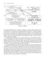
As summarized in the previous sections, a mechatronics system can be partitioned into function blocks
illustrated in Fig. 20.1. In this chapter, we will focus on the actuator portion of the system. Specifically,
we will present a general discussion of the types of electromechanical actuators and their interaction
George T C. Chiu
Purdue University
C. J. Fraser
University of Abertay Dundee
Ramutis Bansevicius
Kaunas University of Technology
Rymantas Tadas Tolocka
Kaunas University of Technology
Massimo Sorli
Politecnico di Torino
Stefano Pastorelli
Politecnico di Torino
Sergey Edward Lyshevski
Purdue University Indianapolis
0066_Frame_C20 Page 1 Wednesday, January 9, 2002 5:41 PM
©2002 CRC Press LLC
energy side of the device. Typically, an LED source is combined with either a phototransistor or photo
thyristor, see Fig. 20.35. In addition to signal isolation, optoisolators also help to reduce ground loop
issues between the logic and power side of the circuit.
Grounding
It is important to provide common ground among the different devices. For electromechanical actuators,
the high energy side is often switching at high frequency; if the ground point of the high energy side of
the circuit is directly connected to the ground of the low energy side of the circuit, switching noise may
propagate through the ground wire and negatively affect the operation of the low energy side of the
system. It is recommended that separate common grounds are established for the high and low energy
side and the two grounds are then connected at the power supply. In addition, an adequate-sized ground
plane needs to be provided to minimize the possibility of differences among grounding points.
20.2 Electrical Machines
C. J. Fraser
The utilization of electric motors as the power source in a mechatronic application is substantial. Electric
motors, therefore, often feature as the prime mover in a variety of driven systems. It is usually the
mechanical features of the application that determines the type of electric motor to be employed. The
torque–speed characteristics of the motor and the driven system are therefore very important. It is perhaps
then a paradox that while the torque–speed characteristics of the motor are readily available from the
supplier, the torque–speed characteristics of the driven system are often quite obscure.
The dc Motor
All conventional electric motors consist of a stationary element and a rotating element, which are separated
by an air gap. In dc motors, the stationary element consists of salient “poles,” which are constructed of
laminated assemblies with coils wound round them to produce a magnetic field. The function of the
laminations is to reduce the losses incurred by eddy currents. The rotating element is traditionally called
the “armature” and this consists of a series of coils located between slots around the periphery of the
armature. The armature is also fabricated in laminations, which are usually keyed onto a location shaft.
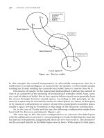
A very simple form of dc motor is illustrated in Fig. 20.56.
The single coil is located between the opposite poles of a simple magnet. When the coil is aligned in
the vertical plane, the conventional flow of electrons is from the positive terminal to the negative terminal.
The supply is through the brushes, which make contact with the commutator segments. From Faraday’s
laws of electromagnetic induction, the “left-hand rule,” the upper part of the coil will experience a force
acting from right to left. The lower section will be subject to a force in the opposite direction. Since the
FIGURE 20.56
Single-coil, 2-pole dc motor.
Magnet
N
+ve
-ve
Brush
Commutator
S
Coil
0066_Frame_C20 Page 33 Wednesday, January 9, 2002 5:49 PM
©2002 CRC Press LLC