Handbook Fractography (1998) WW Part 11 pptx
Bạn đang xem bản rút gọn của tài liệu. Xem và tải ngay bản đầy đủ của tài liệu tại đây (6.72 MB, 60 trang )
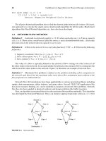
Intentional fracture by overpressurization of ASTM A508, class 2, pressure vessel. The intermediate test
vessel (ITV) was fabricated as part of the Heavy Section Steel Technology (HSST) program at Oak Ridge
National Laboratory, a government-sponsored effort aimed at gaging the toughness of nuclear pressure
vessels. The ITV measured 1 m (39 in.) in outside diameter with a 150-mm (6-in.) thick wall and was
designed for 67-MPa (9.7-ksi) internal pressurization. The preflawed vessel contained a semielliptical
fatigue-cracked defect measuring 205 mm (8 in.) long and 65 mm (2 in.) deep. Failure occurred at the
55 °C (130 °F) test temperature and an internal pressure of 198 MPa (28.7 ksi) nearly three times the
design pressure allowed by the ASME code and four times the probable operating pressure. Fig. 576:
Fracture surface. Note machined and fatigue precracked flaw at top center. Region of fatigue sharpened
notch had a dimpled morphology; farther away from the flaw, a cleavage morphology. Fig. 577:
Schematic of fracture surface in Fig. 576. Initial failure was by ductile tearing.Flaw grew to
approximately 500 mm (20 in.) long and 100 mm (4 in.) deep before onset of brittle propagation. (D.A.
Canonico, C-E Power Systems, Combustion Engineering Inc.)
∆K
m
in
Effect of inclusions on fatigue crack propagation (FCP) in ASTM A514F. Direction of FCP is toward
the top. Fig. 581: Area of fracture surface not near inclusion formations shows primarily ductile
fatigue striations. Also note secondary cracking. Through-thickness (S-T orientation) FCP specimen at
∆K = 55 MPa
m
(50 ksi
in
). SEM, 1020×. Fig. 582 and 583: Through-thickness (S-L orientation)
fractures near inclusion formations at two levels of ∆K. At the low 22-MPa
m
(20-ksi
in
) level (Fig.
582), fatigue damage is by striation formation in the interinclusion material of an inclusion formation.
At the high 55-MPa
m
(50-ksi
in
) level (Fig. 583), ductile fracture (microvoid coalescence) of the
interinclusion material occurs. See also Fig. 579 and 580. SEM, both at 1020× (A.D. Wilson, Lukens
Steel Company)
Brittle fracture of tension flange for large box-girder bridge. The flange measured 75 cm (30 in.) wide
and 55 mm (2 in.) thick and was welded to a trapezoidal box girder. It was made of 55-mm (2 -in.)
thick ASTM A517H plate. Failure occurred catastrophically across the full width of the flange as the
concrete deck of the bridge was being placed. Fracture was arrested about 100 mm (4 in.) down the
web of the girder. Ambient temperature: 14 °C (58 °F). Cause of fracture was inadequate toughness in
the quenched and tempered 690-MPa (100-ksi) minimum yield strength steel. At the time, toughness in
A517 was assumed and was not a specification requirement as it is now. Also, the then-current
specification limited maximum thickness to 50 mm (2 in.). However, thicker plate was allowed for this
application. Fig. 584: Fracture surface of flange. Chevrons point to origin at right. Fig. 585: Close-up
of fracture origin (right) at weld between flange and cross bracing. Fig. 586 and 587:
Photomicrographs of structure of failed flange near the surface (Fig. 586) and at the center (Fig. 587)
of the 55-mm (2 -in.) thick plate. Both at 500× (C.E. Hartbower, Consultant)
Effect of inclusions on FCP in ASTM A533B. The conventionally melted electric furnace steel was
water quenched from 900 °C (1650 °F), tempered at 670 °C (1240 °F), air cooled, stress relieved at 595
°C (1100 °F), and then furnace cooled. FCP specimen tested in the through-thickness (S-T, S-L)
orientations. Direction of fatigue crack propagation is toward the top. Fig. 588: Fracture surface of S-
L oriented FCP test specimen. Fracture surface appearance due to inclusion formation on depressions
or plateaus on the fracture surface. Figures 589, 590, and 591 show three kinds of MnS inclusions in
type II MnS inclusion formations: highly elongated (Fig. 589), flattened or pancaked (Fig. 590), and
small and round as a result of homogenization (Fig. 591). SEM, Fig. 589 and 590: 230×, Fig. 591: 200×
Fig. 592: Alumina (Al
2
O
3
) galaxies on the through-thickness fracture surface of A533B. SEM, 200×.
∆K in Fig. 589, 590, and 592 = 25 MPa
m
(23 ksi
in
); in Fig. 591, 58 MPa
m
(53 ksi
in
). See also
Fig. 593, 594, 595, 596, 597, and 598. (A.D. Wilson, Lukens Steel Company)
∆K
m
in
∆K
m
in
Effects of inclusions on fatigue crack propagation (FCP) in ASTM A533B. In conventional electric
furnace steel, protrusions perpendicular to the direction of FCP were noted on T-S and L-S fracture
surfaces. The protrusions result from inclusion formations (type II MnS and Al
2
O
3
) acting as crack
deflectors. Figures show T-S orientation features. FCP direction is toward the top. Fig. 595:
Protrusions on fracture surface. Fig. 596: Metallographic cross section reveals MnS inclusions on a
protrusion. 170×. Fig. 597: Protrusion. SEM, 15×. Fig. 598: Protrusion with Al
2
O
3
galaxy. SEM, 28°
tilt angle, 325×. Fig. 597 and 598 at ∆K of 40 MPa
m
(36 ksi
in
). See also Fig. 588, 589, 590, 591,
592, 593, and 594. (A.D. Wilson, Lukens Steel Company)
Cavitated intergranular fracture due to hydrogen of ASTM A533B. The specimen of pressure vessel
steel yield strength, 630 Mpa (91.5 ksi) was exposed for more than 1000 h to temperatures above 550
°C (1020 °F) and gaseous hydrogen at a pressure greater than 17 MPa (2.5 ksi). Under these
conditions, hydrogen diffuses into the steel, reacts with thermodynamically less stable carbides, and
forms bubbles of methane gas along grain boundaries. Mechanical properties plummet and, under
impact, failure occurs by rapid coalescence of the methane bubbles, each nucleated at a submicron
carbide or inclusion, along prior-austenite grain boundaries. These cavitated intergranular fractures
are common in steels used for hydrogen service (hydrocracking or coal conversion processes, for
example) and resemble both failures in "overheated" steel, where reprecipitation of fine grain
boundary sulfides due to an overly high austenitization temperature provides the source of the voids,
and high-temperature creep cavitation fractures, where voids form at carbides and grow by vacancy
coalescence and matrix creep. Fig. 599: Fracture surface of Charpy specimen. Note secondary
cracking due to severe bubble coalescence along grain boundaries. SEM, 125×. Fig. 600: Same as Fig.
599, but at higher magnification. Note nucleus at bottom of each cavity. SEM, 3330× (R.H. Dauskardt
and R.O. Ritchie, University of California)
μ
Failure of AISI type 304 tube due to chloride stress-corrosion cracking (SCC) from the outside in. The
oil feed tube was used in a paper mill, where relative humidity was 100%. Cracks and evidence of
corrosion were found under the coating of the painted side of the tube. No damage was noted on the
other, unpainted side. Torsional stresses in service and chlorides in the paint (at a level of 6600 ppm)
provided the conditions necessary for chloride SCC. Fig. 630: Crack on painted side of tube. Angle
reveals influence of torsional stresses. Fig. 631: Stress-corrosion cracks extending from the outside
diameter of the tube (at top) toward its inner diameter. 10% oxalic acid electrolytic etch; 28×. Fig. 632:
Fractured tube. Branching of crack verifies that fracture occurred from the outside diameter (at top)
in. 10% oxalic acid electrolytic etch; 28× (Z. Flanders, Packer Engineering Associates, Inc.)
x
x
Hydrogen-embrittlement failure of AISI type 304 bellows. The component was made by rolling sheet
into tube, seam welding, and then forming. Continuous pressurization with gaseous hydrogen at 172
kPa (25 psi) induced hydrogen embrittlement at roots of bellows convolutes, regions where residual
stresses from forming were at a maximum. Fig. 634 and 635: Bellows assembly and hydrogen-induced
circumferential cracks at A and B. Fig. 636, 637, and 638: Microstructure of fifth convolute cross
section, showing twins, transgranular and intergranular fracture modes, and secondary cracking.
Oxalic acid electrolytic etch, 10×, 50×, and 200×, respectively (R.J. Schwinghamer, NASA Marshall
Space Flight Center)
μ