Foseco Non-Ferrous Foundryman’s Handbook Part 13 ppsx
Bạn đang xem bản rút gọn của tài liệu. Xem và tải ngay bản đầy đủ của tài liệu tại đây (355.35 KB, 20 trang )
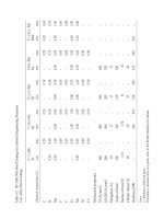
Table 16.1 Copper and copper alloy ingots and castings – comparison of BS1400 and BS EN 1982 Showing near equivalents where standardised in BS EN 1982 and original
compositional symbols for guidance where no near equivalent is included. See Table 16.2 for full details of composition and properties.
Nearest equivalent in
old BS 1400 or
BS4577
BS EN or ISO symbol
for castings (1)
BS EN material
designation
number for
castings (2)
BS EN relevant casting processes and designations (3)
GM
Diecasting
GS
Sand
GZ
Centrifugal
GP
Pressure-die
GC
Continuous
Cooper and Copper-chromium (High conductivity coppers)
HCCl Cu–C CC040A ✓✓
CC1–TF CuCr1–C CC140A ✓✓
A4/1 G–CuNiP
A3/2 G–CuNi2Si
A3/1 G–CuCo2Be
A4/2 G–CuBe
Copper–zinc (Brasses)
DZR1 CuZn35Pb2Al–C CC752S ✓✓
DZR2 CuZn33Pb2Si–C CC751S ✓
CuZn37Pb2Ni1AlFe–C CC753S ✓
PCB1 G–CuZn40Pb
DCB1 CuZn38Al–C CC767S ✓
DCB2 G–CuZn37Sn
DCB3 CuZn39Pb1Al–C CC754S ✓✓✓✓
– CuZn39Pb1AlB–C CC755S ✓✓
SCB1 G–CuZn25Pb3Sn2
SCB2 G–CuZn30Pb3
SCB3 CuZn33Pb2–C CC750S ✓✓
SCB4 G–CuZn36Sn
SCB5 G–CuZn10Sn
SCB6 CuZn15As–C CC760S ✓
– CuZn16Si4–C CC761S ✓✓ ✓
– CuZn32Al2Mn2Fe1–C CC763S ✓✓
– CuZn34Mn3Al2Fe1–C CC764S ✓✓✓
HTB1 CuZn35Mn2Al1Fe1–C CC765S ✓✓✓ ✓
HTB2 G–CuZn36Al4FeMn
HTB3 CuZn25Al5Mn4Fe3–C CC762S ✓✓✓ ✓
– CuZn37Al1–C CC766S ✓
Copper–tin (Gunmetals and Phosphor-bronzes)
CT1 CuSn10–C CC480K ✓✓✓ ✓
PB1 CuSn11P–C CC481K ✓✓✓ ✓
– CuSn11Pb2–C CC482K ✓✓ ✓
PB2 CuSn12–C CC483K ✓✓✓ ✓
CT2 CuSn12Ni2–C CC484K ✓✓ ✓
PB4 G–CuSn10PbP
LPB1 G–CuSn7PbP
Copper–tin–lead (Gunmetals and Leaded bronzes)
LG1 CuSn3Zn8Pb5–C CC490K ✓✓ ✓
LG2 CuSn5Zn5Pb5–C CC491K ✓✓✓ ✓
LG3 G–CuSn7Pb4Zn2
LG4 CuSn7Zn2Pb3–C CC492K ✓✓✓ ✓
– CuSn7Zn4Pb7–C CC493K ✓✓✓ ✓
LB1 CuSn7Pb15–C CC496K ✓✓ ✓
LB2 CuSn10Pb10–C CC495K ✓✓✓ ✓
LB3 G–CuSn10Pb5
LB4 CuSn5Pb9–C CC494K ✓✓✓ ✓
LB5 CuSn5Pb20–C CC497K ✓✓ ✓
G1 G–CuSn10Zn2
G2 G–CuSn8Zn4Pb
G3 G–CuSn7Ni5Zn3
Copper–aluminium (Aluminium bronzes)
– CuAl9–C CC330G ✓✓
AB1 CuAl10Fe2–C CC331G ✓✓✓ ✓
CuAl10Ni3Fe2–C CC332G ✓✓✓ ✓
AB2 CuAl10Fe5Ni5–C CC333G ✓✓✓ ✓
– CuAl11Fe6Ni6–C CC334G ✓✓✓
AB3 G–CuAl6Si2Fe
Copper–manganese–aluminium
CMA1 CuMn11Al8Fe3Ni3–C CC212E ✓
CMA2 G–CuMn13Al9Fe3Ni3
Copper–nickel (cupro-nickels)
– CuNi10Fe1Mn1–C CC380H ✓✓ ✓
– CuNi30Fe1Mn1–C CC381H ✓✓
CN1 CuNi30Cr2FeMnSi–C CC382H ✓
CN2 CuNi30Fe1Mn1NbSi–C CC383H ✓
(1) Symbol finishes with B for material in ingot form.
(2) Number begins CB for material in ingot form.
(3) GM – permanent mould casting. GS – sand casting. GZ – centrifugal. GP – pressure diecasting. GC – continuous casting.
Method of casting affects properties significantly.
Note: Ingots are not specified for high conductivity coppers.
230 Foseco Non-Ferrous Foundryman’s Handbook
Copper and copper alloy castings 231
232 Foseco Non-Ferrous Foundryman’s Handbook
Melting copper and copper-based alloys
The melting of copper and copper-based alloys presents special problems.
Molten copper dissolves both oxygen and hydrogen and on solidification, the
oxygen and hydrogen can combine to form water vapour which causes
porosity in the casting, Figs 16.1–16.4. Without the presence of oxygen,
hydrogen alone may also cause gas porosity. Alloys containing aluminium
form oxide skins which can cause problems in castings. In other alloys, traces
of aluminium can cause defects and residual aluminium must be removed.
Special melting and metal treatment techniques have been developed to deal
with these effects. These include fluxing, degassing and deoxidation
treatments. Foseco supplies products for each of these treatments.
Foseco products for the melting and treatment of copper and
its alloys
ALBRAL Fluxes for treatment of alloys containing Al, they dissolve
and remove alumina.
CUPREX Oxidising fluxes for preventing hydrogen pick-up during
melting, Table 16.3.
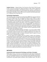
Figure 16.1 Solubility of hydrogen in copper. (From Neff, D.V. (1989) Hydrogen
and oxygen in copper, AFS Trans., 97, 439–450.)
Copper and copper alloy castings 233
Figure 16.2 Effect of alloying elements on hydrogen solubility in copper melts.
(From Neff, D.V. loc. cit.)
Figure 16.3 Copper–copper oxide phase diagram. (From Neff, D.V. loc. cit.)
234 Foseco Non-Ferrous Foundryman’s Handbook
CUPRIT Neutral or reducing fluxes, they protect alloys from
oxidation and reduce zinc loss, Table 16.4.
DEOXIDISING
TUBES For deoxidising copper and its alloys, Table 16.6.
ELIMINAL Flux for removing aluminium from melts.
MDU Mobile Degassing Unit for the removal of hydrogen.
LOGAS 50 Briquettes for the removal of hydrogen, Table 16.5.
PLUMBRAL Covering and scavenging flux for treating high lead
alloys.
RECUPEX Fluxes for melting copper alloy swarf, skimmings and
scrap.
RECUPEX 250 Reducing, protective flux for use when metal is held
molten for a long time, e.g. during continuous casting.
SLAX 20 Slag coagulant.
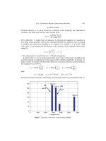
Figure 16.4 Equilibrium between hydrogen and oxygen in copper melts. (From
Neff, D.V.)
Table 16.3 CUPREX oxidising fluxes and their applications
Product Form Application
rate (%)
Alloys Slag
CUPREX 1 Blocks 1 Commercial copper, gunmetal Fluid
CUPREX 100 Powder 0.5–1 Tin/lead bronzes (<10% Pb) and
copper–nickel alloys
Fluid
CUPREX 160 Powder 1–2 Commercial copper, bronzes, gunmetal,
Ni–brass alloys melted in crucible or
reverberatory furnaces
Plastic,
dry
Copper and copper alloy castings 235
Table 16.4 CUPRIT reducing fluxes and their applications
Metal Furnace CUPRIT
type
Recommended procedure
Brass
Brazing metals
Gilding metals
Crucible 1 Use 1% addition rate of CUPRIT.
Place briquettes in the bottom of
the hot crucible and charge metal
on top. Leave the slag intact until
the crucible is withdrawn from the
furnace.
81
49
Add 1% CUPRIT at an early stage
in melting. Leave slag intact until
the crucible is withdrawn.
Small
reverberatory
1 Place briquettes at the bottom of
the hot furnace and add the
charge. Use 1% CUPRIT.
Electric 49 Add 0.5% CUPRIT in two stages,
add the major portion to the heel
and the remainder for final
drossing-off. Skim before pouring.
HC copper Crucible
Electric
81 Add 1% CUPRIT at an early stage
in melting. Leave the slag intact
until the metal is tapped or the
crucible withdrawn.
Brass
Brazing metals
Gilding metals
Comm. copper
Electric
low freq.
induction
81 0.75% CUPRIT is needed. Add
0.6% together with charge, stir in
the balance before drossing-off.
More flux may be needed if the
charge consists of swarf.
Brass
Brazing metals
Gilding metals
Al–bronze
Si–bronze
Mn–bronze
All types
of reverb.
furnace
81 Add 0.5% at the beginning of
melting. During melting add more
to maintain a flux cover. 1% total
may suffice depending on the
surface of molten metal exposed.
Table 16.5 LOGAS 50 degassing tablets
Unit No. 1A 3B
Melt wt. treated kg 0–50 250–380
236 Foseco Non-Ferrous Foundryman’s Handbook
CUPREX oxidising fluxes and their applications
CUPREX formulations evolve oxygen to produce oxidising conditions and a
scavenging gas to remove most of the dissolved hydrogen, thus preventing
the steam reaction which causes porosity in castings. CUPREX also forms a
flux cover to prevent the pick-up of more hydrogen from the furnace
atmosphere and remove non-metallic material, Table 16.3.
CUPRIT neutral or reducing fluxes
The CUPRIT range is produced in briquette and powder form:
Briquettes CUPRIT 1
Powder CUPRIT 49, 81, 103
CUPRIT briquettes are pre-weighed while the powders are available in pre-
weighed packets or in bulk. The main functions of CUPRIT are:
To form a protective blanket over the metal during melting to prevent
contamination of the melt from the furnace atmosphere and to protect
alloying elements, especially zinc, from oxidation, thereby suppressing
zinc fume and the formation of showers of zinc oxide in the air.
Table 16.6 Grades of DEOXIDISING TUBES and their use
Alloy DEOX.
TUBE
Weight of melt (kg)
25 50 75 100 200 400
Commercial
copper
DS 2 × DS3 3 × DS4 6 × DS3 6 × DS4 3 × DS6 6 × DS6
HCC (high
conduct.)
DS &
CB
1 × DS1 +
1 × CB3
1 × DS2 +
2 × CB3
1 × DS3 +
3 × CB3
2 × DS4 +
1 × CB6
2 × DS4 +
2 × CB6
1 × DS6 +
4 × CB6
Brass DS 1 × DS1 1 × DS2 1 × DS3 1 × DS4 2 × DS4 1 × DS6
Bronze &
gunmetal
DS 1 × DS2 1 × DS3 1 × DS4 1 × DS5 3 × DS4 4 × DS5
Al-bronze &
Mn–bronze
E1 × E1 2 × E1 3 × E1 2 × E3 4 × E3 8 × E3
Nickel–silver
castings
E &
DS
1 × E3 +
1 × DS2
2 × E3 +
1 × DS4
3 × E3 +
2 × DS3
4 × E3 +
2 × DS6
8 × E3 +
1 × DS6
16 × E3 +
2 × DS6
Nickel–silver
for hot & cold
working
NS 1 × NS4 2 × NS4 3 × NS4 1 × NS6 2 × NS6 4 × NS6
Ni–bronze
Cu–Ni alloys
MG 2 × MG5 3 × MG5 2 × MG6 3 × MG6 6 × MG6 12MG6
Copper and copper alloy castings 237
To dissolve impurities from the melt.
To form an inert atmosphere for the melting of high conductivity
copper (CUPRIT 81 flux).
To provide a mould and launder cover for the direct-chill casting of
brass and copper (CUPRIT 103 flux).
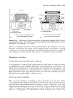
Rotary degassing of copper and its alloys
The Mobile Degassing Unit (Fig. 6.2) is effective for removing hydrogen
from copper melts and should be used in the way described for aluminium
alloys in Chapter 6.
LOGAS degassing units
LOGAS degassing units comprise a mixture of chemicals which, on contact
with molten metal, decompose to release a steady stream of non-reactive
gas. LOGAS is carefully dried and packed in foil, so the gas bubbles contain
very little hydrogen and are able to flush out hydrogen from the melt.
Deoxidants for copper and its alloys
The ideal deoxidant should function as follows:
1 It should combine with all the oxygen present to form a fluid slag.
2 Deoxidation products should not be entrained in the solidified casting.
3 Residual deoxidant should not adversely affect the physical properties of
the alloy and should prevent further oxidation during pouring.
Phosphorus satisfies most of these requirements, but a residual content of
0.025% is necessary to ensure adequate deoxidation. This can seriously affect
the conductivity of pure copper and causes embrittlement of high nickel
bearing alloys.
Alternative deoxidants are:
MAGNESIUM: Very effective and it eliminates the harmful effects of
sulphur, but the oxide formed tends to remain entrapped in the metal
at grain boundaries, causing embrittlement.
MANGANESE: An excellent deoxidant, present in DEOXIDISING
TUBES E. Manganese imparts some grain refinement.
CALCIUM: A good deoxidant, although metal fluidity is slightly
reduced.
SILICON: Deoxidises well but the oxide formed may affect the surface
appearance and pressure tightness of the casting.
238 Foseco Non-Ferrous Foundryman’s Handbook
BORON: A satisfactory deoxidant having some grain-refining action.
Excess can cause embrittlement.
DEOXIDISING TUBES L are also available for commercial and h.c.
copper, Ni–bronze, Cu–Ni alloys and Al–bronze. They contain lithium
and remove hydrogen as well as deoxidise.
Copper-based alloy castings are usually made from charges using pre-
alloyed ingot together with foundry returns (runners, risers and scrap
castings). Such internal scrap must be carefully segregated to avoid mixing
of metal of different specifications. With successive remelting there will be a
tendency to lose volatile elements, particularly zinc, and to pick up
contaminants such as iron. The level of residual phosphorus may vary,
depending on the deoxidation practice used, and it must be carefully
monitored.
The alloys are frequently melted in gas-fired furnaces, usually crucible
furnaces. Medium frequency induction fumaces are also used with silica or
alumina linings. Clay–graphite or silicon carbide crucibles can also be used,
the electrical conductivity of the crucible allowing it to absorb induction
power, yielding higher crucible temperatures and reduced stirring in the
melt.
The melting and treatment of each of the main alloy types will be dealt
with in turn.
Melting and treatment of high conductivity copper
The quality of high conductivity copper is measured by its electrical
conductivity. Pure copper in the annealed condition has a specific electrical
resistance of 1.72 microhms per cubic cm at 20°C. This is said to have 100%
electrical conductivity IACS (International Annealed Copper Standard
units). Cast copper can have a conductivity of 90% IACS and has both
electrical and thermal applications since high electrical conductivity also
implies high thermal conductivity. Many of the impurities likely to be
present in copper lower its electrical conductivity seriously, Table 16.7.
Cu–C (HCC1) copper is used for water-cooled tuyeres and electrode
clamps, it must have 86% IACS minimum so must be of high purity with
only small additions of Cr or Ag to extend the freezing range and make
casting easier.
For less onerous duties, copper having tin or zinc up to 2% may be used.
A degree of conductivity is sacrificed to allow better casting properties and
for ease of machining.
Where greater hardness and strength are required, copper–chromium
castings CC1-TF may be used. This alloy requires to be heat treated (1 hour
at 900°C, followed by quenching to room temperature and reheating to
500°C for 1–5 hrs) to realise its full properties.
High purity copper is particularly prone to gas porosity problems due
both to hydrogen and the hydrogen/oxygen reaction which occurs if any
Copper and copper alloy castings 239
oxygen is present in the molten metal. Steps must be taken, during melting,
to exclude both hydrogen and oxygen from the melt. The principles
involved are:
Melt quickly, using the lowest temperature possible, under a reducing
cover flux
Purge with an inert gas to remove hydrogen
Add deoxidants to remove residual oxygen, ensuring that residual
deoxidant does not reduce the conductivity
Melting
The charge materials must be carefully selected to avoid impurities which
can reduce the conductivity. Before charging, the copper must be clean and
degreased to avoid any hydrogen-containing contaminants. Clean and dry
crucibles, lids, plungers and slag stoppers must be used. The crucible should
be preheated before charging to minimise the time that the copper is solid
and unprotected by flux. Melt down under a reducing cover of CUPRIT 81;
the flux should be placed in the bottom of the crucible prior to charging. 1 kg
of CUPRIT 81 is needed per 100 kg of metal.
Table 16.7 The effect of impurities and alloying elements on the
electrical conductivity of pure copper
Impurity % % IACS
Aluminium 0.1 85
Antimony 0.1 90
Arsenic 0.1 75
Beryllium 0.1 85
Cadmium 1.0 90
Chromium 1.0 80
Calcium 0.1 98
Iron 0.1 70
Magnesium 0.1 94
Manganese 0.1 88
Nickel 0.1 95
Phosphorus 0.1 50
Silicon 0.1 65
Silver 1.0 97
Tin 1.0 55
Zinc 1.0 90
240 Foseco Non-Ferrous Foundryman’s Handbook
Degassing
Hydrogen is removed from the melt by bubbling an inert gas through the
melt. This can be done using argon or nitrogen using the Mobile Degassing
Unit (see Chapter 6) or less effectively by injecting gas through a graphite
tube immersed deep into the melt. 50–70 litres of gas are needed for each
100 kg of copper.
An alternative way to degas is to plunge LOGAS 50 briquettes into the
melt. LOGAS is a granular material, strongly bonded and formed into a
weighed unit with high surface area/volume ratio to ensure maximum
contact area with the liquid metal. On contact with the metal, LOGAS 50
decomposes releasing a steady stream of non-reactive gas which flushes out
the hydrogen. LOGAS 50 units are packed in foil, they are of annular shape
having a central hole into which a refractory-coated steel plunger can be
inserted, Table 16.5.
Treatment takes from 3 to 10 minutes depending on the size of the melt.
Some loss of temperature occurs during treatment, so the initial treatment
temperature must be chosen accordingly. The minimum temperature
practicable should be used.
Deoxidation
A number of deoxidants are available for copper (Table 16.6). They combine
with the dissolved oxygen in the metal forming stable oxides which float out
of the melt. Phosphorus is the most widely used deoxidant for copper and
its alloys because of its effectiveness and low cost. It must be used sparingly
with high conductivity copper since any residual phosphorus left in solution
seriously lowers the conductivity of the copper (Table 16.7).
The recommended practice is to use phosphorus to remove most of the
dissolved oxygen and to complete the deoxidation with a calcium boride or
lithium-based deoxidant.
The precise quantity of deoxidant needed depends on the melting practice
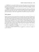
used. Simple tests can be made in the foundry to observe the solidification
characteristics of the melt. Open-topped cylindrical test moulds having
impressions about 75 mm high by 50 mm diameter are needed. They can be
formed in a cold-setting resin or silicate sand mixture. When the melt is
ready for deoxidation, a sample of the copper should be ladled into one of
the moulds and allowed to solidify. If the head rises appreciably as shown
in Fig. 16.5a very gassy metal is indicated. DEOXIDISING TUBES DS
containing phosphorus must be plunged and further test castings made. At
the point when the quantity of phosphorus added results in a shallow sink
in the head, as in Fig. 16.5 b, it can be assumed that the residual phosphorus
content of the melt is nil and a small amount, about 0.008% of oxygen,
remains.
Deoxidation is now completed by plunging DEOXIDISING TUBES CB or
L, adding sufficient to produce a test casting having a head with a deep sink
Copper and copper alloy castings 241
as in Fig. 16.5 c. The melt is now in a condition to produce castings free from
porosity. The approximate additions needed are shown below:
Weight of melt
DEOXIDISING
TUBES
25 kg 50 kg 75 kg 100 kg 200 kg 400 kg
DS & 1 ϫ DS1 1 ϫ DS2 1 ϫ DS3 2 ϫ DS4 2 ϫ DS4 1 ϫ DS6
CB 1 ϫ CB3 2 ϫ CB3 3 ϫ CB3 1 ϫ CB6 2 ϫ CB6 4 ϫ CB6
DEOXIDISING TUBES L, containing lithium, can be used as the final
deoxidant in place of DEOXIDISING TUBES CB. An application rate of
0.018–0.02% of product should be used. In addition to being an excellent
deoxidant, lithium also removes traces of hydrogen. This is found to reduce
the incidence of cracks in complex cast shapes.
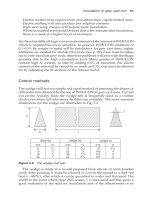
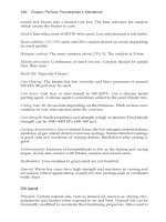
Casting conditions
HC copper, being almost pure copper, has an extremely short freezing range.
It is very weak at the point of solidification so that moulds and cores must
not be too strong. Resin bonded sand is suitable and the resin percentage
must be as low as possible, the minimum necessary for handling the mould
and cores. Gating should be designed to minimise turbulence on pouring, in
order to avoid the possibility of oxygen pick-up, Figs 16.6 16.7 (see Chapter
7). Feeding of the castings follows the practice used for steel castings (see
Chapter 17).
Figure 16.5 The appearance of test castings: (a) Gassy metal. (b) Partially
deoxidised. (c) Fully deoxidised.
242 Foseco Non-Ferrous Foundryman’s Handbook
Recommended casting temperatures
Light castings < 15 mm section 1250°C
Medium castings 15–40 mm section 1200°C
Heavy castings >40 mm section 1150°C
Melting and treatment of high conductivity
copper alloys
Copper–silver
Silver additions should be made in the form of Cu–Ag master alloy and
introduced into the melt after degassing but prior to deoxidation. The same
dual deoxidation process used for pure copper is recommended.
Figure 16.6 Gating high conductivity or commercial
copper castings, single ingate.
The simplest form of gating for small to medium size
castings.
1. Tapered sprue to reduce formation of air bubbles.
2. Deep basin to receive first turbulent impact of metal.
3. Ingate tapering out to reduce metal velocity. Note
position of ingate at top of sprue basin.
Figure 16.7 Gating high conductivity or
commercial copper castings, multiple ingates.
For castings of large surface area where more
than one ingate helps to fill mould uniformly.
1. Sprue and basin as in Fig. 5.6.
2. Progressively narrowing runner to keep
runner bar full; this reduces dross formation.
Note runner bar extention to trap dross.
Copper and copper alloy castings 243
Copper–cadmium
Degassing and deoxidation by the dual treatment must be completed before
cadmium is added. The molten copper can be tapped directly onto pure
cadmium metal as the metal is transferred from the melting furnace to a
pouring ladle. The use of a Cu–Cd master alloy is preferable, since lower
cadmium losses occur. Molten cadmium evolves toxic brown fumes so good
ventilation is needed.
Copper–chromium
Cu–Cr master alloy should be added after degassing but before deoxida-
tion. The chromium alloy should be thoroughly stirred in to ensure a
homogeneous solution. A chromium loss of 10–30% may be expected
depending on the state of oxidation of the melt. Phosphorus additions
should only be made if a test casting shows a rising head. Normally the
chromium addition and a final deoxidation with calcium-boride or lithium
is sufficient. Any residual phosphorus left in the alloy will upset its response
to heat treatment.
Commercial copper
Commercial copper castings contain up to 2% of tin and/or zinc for ease of
casting and machining. The conductivity is reduced to a minimum of 55%
IACS but this is adequate for many applications. A simpler fluxing and
deoxidising technique can be used. Melting can be carried out under
oxidising conditions and phosphorus alone can be used for deoxidation.
Hydrogen degassing is not usually necessary since CUPREX oxidising
fluxes evolve oxygen and scavenging gases which eliminate most of the
hydrogen.
Treatment
Melt down under an oxidising cover of CUPREX (either CUPREX 1 blocks
or CUPREX 100 powder), Table 16.3. Four 250 g blocks should be used for
100 kg of metal (1%). The CUPREX should be placed in the bottom of the
empty crucible which is preheated to redness. In other furnaces, add the
CUPREX at an early stage in melting. The fluid slag must be removed before
deoxidation, using SLAX to thicken the slag if necessary. Deoxidise before
pouring using DEOXIDISING TUBES DS at the following rate:
Wt. of melt (kg) 25 50 75 100 200 400
No. of tubes 2 ϫ DS3 3 ϫ DS4 6 ϫ DS3 6 ϫ DS4 3 ϫ DS6 6 ϫ DS6
244 Foseco Non-Ferrous Foundryman’s Handbook
Casting conditions
See recommendations for HC copper.
Recommended casting temperatures
Light castings <15 mm section 1250°C
Medium castings 15–40 mm section 1200°C
Heavy castings >40 mm section 1150°C
Melting and treatment of brasses, copper–zinc alloys
Effect of added elements
Aluminium: Unless added for a definite purpose, as in diecasting brass, it
should be absent. It improves fluidity and definition, which is valuable in
diecastings, but it oxidises readily causing oxide films and inclusions which
may cause porosity and unsoundness in sand castings.
Iron: Small quantities have a grain-refining effect and increase hardness and
tensile strength.
Lead: Improves machinability. Lead is insoluble in brass and exists as
globules, which should be dispersed as uniformly as possible. It must not be
allowed to segregate.
Manganese: Sometimes used as a deoxidant, its effect is similar to iron.
Nickel: Improves the mechanical properties and increases corrosion resist-
ance. It also has a tendency towards grain refinement.
Phosphorus: Combines with any iron present, increasing hardness. Reduces
grain growth and improves fluidity.
Silicon: Makes founding more difficult but improves corrosion resistance
and fluidity.
Tin: Raises tensile strength and hardness at the expense of ductility and
improves corrosion resistance and fluidity.
Principles of melting and treating brasses
Zinc vapour pressure in molten brass is sufficient to prevent ingress of
hydrogen into the metal, so a neutral or reducing atmosphere is not
deleterious. An oxidising atmosphere must be avoided since it would cause
Copper and copper alloy castings 245
loss of zinc though oxidation. Zinc can also be lost through volatilisation, so
a liquid flux cover is needed. To avoid zinc loss, the charge should be melted
as quickly as possible and not be allowed to overheat.
Removal of impurities
ELIMINAL is a powdered flux range designed to reduce aluminium (and
silicon) in copper-based alloys. Up to 0.5% Al may be removed from brass by
means of ELIMINAL 2. Where higher levels exist, it is recommended that
the charge is diluted with Al-free material to bring the Al content down to
0.5% or less. If the Al content is around 0.5%, the charge should be melted
down under a cover of 0.5% by weight of ELIMINAL. This will also protect
the zinc content of the melt. Before pouring, the metal should be brought to
a temperature slightly higher than that required normally and 0.5% of
ELIMINAL should be rabbled in or plunged to ensure maximum mixing,
which is essential for efficient removal. The treatment is repeated until the
Al content is reduced to the desired level. The metal is deoxidised
immediately before pouring.
When melts contain 0.4%Al, ELIMINAL removes about 40% of its own
weight of Al
When melts contain 0.2%Al, ELIMINAL removes about 25% of its own
weight of Al
When melts contain 0.1%Al, ELIMINAL removes about 20% of its own
weight of Al
When aluminium has been removed to a low level, ELIMINAL will then
remove silicon and manganese from copper alloys but at a slower rate than
aluminium.
Melting brasses for sand castings
1 Heat up the crucible or furnace.
2 Place in the bottom of crucible or furnace CUPRIT 1 blocks equal to 1 kg
per 100 kg of metal to be melted (Table 16.4).
3 Charge ingots and scrap and melt down as rapidly as possible,
maintaining an intact cover of fused flux. CUPRIT 49 powder may be
used instead of blocks. This should be added at the same rate as soon as
the first part of the charge reaches a pasty condition.
4 Bring the metal up to pouring temperature and avoid overheating.
5 Immediately prior to pouring, plunge DEOXIDISING TUBES DS at the
rate of one DS2 tube per 50 kg of metal and hold immersed for a few
seconds. (The plunging tool must be preheated and coated with FIRIT or
HOLCOTE 110 to protect the plunger and prevent contamination.)
6 When the metal is at the correct pouring temperature SLAX 20 may be
added to reduce “flaring”, the surface slag should be held back and the
metal poured from underneath it. This will reduce “flaring” to the
minimum.
246 Foseco Non-Ferrous Foundryman’s Handbook
CUPRIT blocks are recommended for use in reverberatory and similar
hearth furnaces, since powder fluxes can be carried away by the draught
from the burners.
Casting conditions (sand castings)
Brasses may be cast easily in green sand or chemically bonded sand moulds.
Pinhole porosity may be a problem, often revealed when the casting is
polished. It occurs particularly at higher pouring temperatures and can be
avoided by application of a graphite-containing coating, such as ISOMOL
185, to the moulds and cores.
Running, gating and feeding
The running of brass castings does not present any real problem. Excessive
turbulence in the mould should be avoided. Methods best suited to long
freezing range alloys should be used (see Chapter 7), with unpressurised or
only slightly pressurised systems based on ratios such as 1:4:6 or 1:4:4. This
type of sprue/runner/ingate system can provide a useful source of feed
metal to the casting as long as the gate remains unfrozen. Indeed, many
thousands of castings (shell mouldings in particular) such as taps, valves,
cocks etc. are made in this way without any supplementary form of feeding.
The alloys go through a mushy stage during freezing and thin sections,
below 10 mm, will often form a dense skin, free from porosity, while the
centre of the section displays dispersed shrinkage porosity. So the castings
may be pressure-tight throughout.
Recommended casting temperatures
<15 mm 15–40 mm >40 mm
60/40–65/35 alloys 1100°C 1050°C 1020°C
80/20–70/30 alloys 1150 1100 1070
Melting diecasting brasses
The diecasting brasses CuZn38Al-C (DCB1), CuZn39Pb1Al-C and CuZn29-
AlB-C (DCB3) are cast by the gravity die (permanent mould) technique. The
alloys contain aluminium which oxidises during melting forming a skin of
Copper and copper alloy castings 247
oxide which results in sluggish pouring, so it is necessary to melt under a
special flux such as the ALBRAL range. ALBRAL fluxes contain chemicals
which dissolve alumina, removing it from the metal by flotation. The surface
layer formed may be either a dry dross or a liquid slag, depending on the
grade of ALBRAL used. From an efficiency aspect, a liquid slag performs
best, but there may be difficulties in removing it in some operations. The
following table indicates the types of ALBRAL available and their method of
application.
ALBRAL fluxes for removing alumina
Product Furnace
type
Dross
type
Addition
during melting
Addition
before pouring
ALBRAL 2 Crucible,
reverb.
Fluid Up to 1% to
form a cover
0.25–0.5% plunge
and rabble
ALBRAL 3 Bale out,
induction
Dry ditto ditto
For melting diecasting brasses:
1 Preheat the crucible or furnace.
2 Charge ingots and scrap and commence melting.
3 When part of the charge becomes pasty, sprinkle ALBRAL 3 (1 kg for
100 kg of metal) over the surface.
4 Continue charging and melt under the protective cover as rapidly as
possible.
5 When the metal is at pouring temperature, add a further quantity of
ALBRAL 3 (0.5 kg for 100 kg of metal) and with a perforated saucer
plunger, plunge the flux to the bottom of the melt, then with a rotary
movement of the plunger, “wash” the flux in, bringing it into intimate
contact with all parts of the melt in order to cleanse it of alumina
particles.
6 After 2–3 minutes, withdraw the plunger and allow the melt to settle.
7 Deoxidise with DEOXIDISING TUBES DS (one DS 2 tube for 50 kg of
metal).
8 When the metal is at the correct temperature (1100°C), Iadle out
as required, pushing the surface dross aside to leave a clean working
area.
9 From time to time, after fresh metal has been added, skim away the dross
and add fresh ALBRAL 3, washing in as before. Similarly, DEOXIDISING
TUBES DS should be plunged occasionally to maintain maximum
fluidity.