Foseco Ferrous Foundryman''''s Handbook Part 4 pot
Bạn đang xem bản rút gọn của tài liệu. Xem và tải ngay bản đầy đủ của tài liệu tại đây (264.09 KB, 25 trang )
Inoculation of grey cast iron
65
Electric melted irons require more inoculation than cupola melted irons.
Electric melting will also produce low sulphur contents.
High steel scrap charges will require more inoculation.
Where inoculated iron is held for more than a few minutes after inoculation,
there is a need of a higher level of treatment.
It is therefore difficult to give an accurate estimate of the amount of INOCULIN
which is required for every situation. In general, INOCULIN additions of
0.1–0.5% by weight of metal will be satisfactory for grey cast irons, higher
additions are needed for ductile (SG) irons (see p. 79). Care must be taken
not to over-inoculate grey irons, otherwise problems will arise with shrinkage
porosity due to too high a nucleation level. Many grades of INOCULIN
contain high Si content, so that by adding 0.5% of inoculant, the silicon
content of the iron will be raised by as much as 0.3%, this must be allowed
for by adjusting the Si analysis of the furnace metal.
Control methods
The wedge chill test is a simple and rapid method of assessing the degree of
chill reduction obtained by the use of INOCULIN in grey cast irons. Carried
out on the foundry floor, the wedge test is frequently used as a routine
check even when full laboratory facilities are available. The most common
dimensions for the wedge are illustrated in Fig. 5.2.
Figure 5.2
The wedge chill test.
h
b
I
t
Base
(b)
Height
(h)
Length
(I)
mm
6
13
19
25
in
1
/
4
1
/
2
3
/
4
1
mm
11
22
38
57
in
7
/
16
7
/
8
1
1
/
2
2
1
/
4
mm
57
100
127
127
in
2
1
/
4
4
5
5
The wedge is made in a mould prepared from silicate or resin bonded
sand. After pouring, it must be allowed to cool in the mould to a dull red
heat (c. 600°C), after which it can be quenched in water and fractured. The
width at the point where clear chill ceases, t, is measured and this gives a
good indication of the need for inoculation and of the effectiveness of an
66
Foseco Ferrous Foundryman’s Handbook
inoculation process. In general, casting sections should be not less than
three times the wedge reading if chill at the edges and in thin sections is to
be avoided.
After ladle inoculation, the metal must be cast quickly to avoid inoculant
fade.
For certain applications such as continuous casting of iron bar or automatic
pouring of castings, inoculant can be added in the form of filled steel wire
containing INOCULIN 25 which can be fed into a ladle or the pouring basin
of an automatic pouring machine at a computer-controlled rate using the
IMPREX Station (see pp. 73, 78). IMPREX wire is available in a range of
diameters from 6 mm upwards.
Late stream inoculation
With the increasing number of foundries where castings are made on highly
mechanised moulding and pouring lines, the requirements for inoculation
are becoming more difficult to meet. Particular difficulties arise with the
use of automatic pouring furnaces where conventional ladle inoculation is
not possible. A method of carrying out inoculation at the casting stage is
needed and this must be consistent and automatic in operation. The MSI 90
Metal Stream Inoculator is intended for use in these conditions.
It is designed to add controlled amounts of inoculant to the liquid cast
iron just before it enters the mould. The use of late stream inoculation
techniques leads to the virtual elimination of fading. This permits a substantial
reduction in the amount of inoculant used. The inoculant addition thereby
produces a smaller change in iron composition leading to improved
metallurgical consistency. The cost of inoculation is also lower.
The MSI 90 Stream Inoculator consists of two units, Fig. 5.3, a control unit
and a dispensing unit linked together by a special cable and air line assembly.
The inoculant dispensing cabinet is located in a fixed position over the
mould being poured. A storage hopper for the inoculant is mounted above
the dispensing cabinet. In the latest version, MSI SYSTEM 90-68E, Fig. 5.4,
the flow of inoculant can be regulated either by optical detection of the start
and end of iron flow via an optical module and fibre optic system or by
connecting the system to the pouring furnace electrical signal used to regulate
the flow of liquid iron. The monitoring system checks INOCULIN 90 level,
dispensing tube status, inoculant flow, gate status, compressed air and
dispensing unit temperature. The monitor can automatically interrupt
pouring in the event of malfunction. The control unit is fitted with a printer
port allowing records to be kept. The control cabinet is positioned in a
secure, easily accessible place and may be some distance from the point of
inoculation.
The MSI 90 Stream Inoculator can be operated in conjunction with a
variety of types of pouring equipment:
Inoculation of grey cast iron
67
Low-voltage electricity
cable and air line
Control
unit
Storage hopper for INOCULIN 90
Sensor to detect
metal stream
Ladle
Metal stream
Dispensing unit
controlling flow of inoculant
Delivery tube for INOCULIN 90
to be added to metal stream
Mould
Figure 5.3
The principles involved in the MSI System 90.
Figure 5.4
MSI System 90 Type 68E.
pouring furnaces
ladle transporters
automatic ladle pouring devices
conventional ladles with fixed or variable pouring positions (provided
the latter is within a limited radius).
68
Foseco Ferrous Foundryman’s Handbook
The inoculant used in late stream inoculators must have a number of important
features:
It must be a powerful inoculant.
It must be finely divided to ensure free-flowing properties and rapid
solution.
It must be very accurately graded, without superfine material which
would blow away, or large particles which jam the gate mechanism.
It must dissolve rapidly and cleanly to avoid the presence of undissolved
inoculant particles in the castings.
Sprue
Filter
Runner
Ingate
INOTAB
cast mould
Inoculant
Ratio of cross-sectional areas:
Sprue : Filter : Runner : Ingate
1 : :1.1:1.2
INOTAB and filter application gating
system deslgn
4 : 8 :3
Conventional gating with INOTAB
cast mould Inoculant
INOTAB cast mould inoculant set in pouring basin
Figure 5.5
Application of INOTAB cast mould inoculant.
Inoculation of grey cast iron
69
These requirements are met by INOCULIN 90, specially developed for this
purpose. INOCULIN 90 is an inoculating grade of ferroalloy containing
balanced proportions of Si, Mn, Al, Ca and Zr, and is an excellent inoculant
for grey and ductile irons. INOCULIN 90 should not be used for normal
ladle inoculation because of its very fine size grading.
Stream inoculation is very efficient since fading is eliminated. The normal
addition rate for grey iron is from 0.03–0.20%, typically 0.1%, much less
than would be used for ladle inoculation. For ductile iron, addition rates
range from 0.06–0.3%, typically 0.2%.
Mould inoculation
There are several ways in which mould inoculation can be performed:
powdered inoculant can be placed in the pouring bush; or it can be placed
at the bottom of the sprue. A more reliable method is to use sachets or
precast slugs of inoculant in the pouring bush or in the running system
(Fig. 5.5).
INOPAK sachets are sealed paper packets containing 5, 10 or 20 g of
graded, fast-dissolving inoculant which can be placed in the runner bush, at
the top of the sprue or in some other situation where there is a reasonable
degree of movement in the metal stream. For most purposes, the addition
rate should be 0.1%, i.e. 5 g of INOPAK for each 5 kg of iron poured.
INOTAB cast mould inoculant tablets are designed to be placed in the
runner where they gradually dissolve in the metal stream as the casting is
poured, giving uniform dissolution. This ensures that inoculation takes place
just before solidification of the iron. Application is simple using core prints
to locate the INOTAB tablet.
INOTAB tablets are normally applied at 0.07–0.15% of the poured weight
of iron. The metal temperature and pouring time of the casting must be
considered when selecting the tablet weight. A minimum pouring temperature
of 1370°C (2500°F) is recommended. It is important that the INOTAB tablet
is located where there is continual metal flow during pouring to ensure
uniform dissolution and the typical application methods are shown in
Fig. 5.5.
Chapter 6
Ductile iron
Production of ductile iron
Ductile iron, also known as spheroidal graphite (s.g.) iron or nodular iron,
is made by treating liquid iron of suitable composition with magnesium
before casting. This promotes the precipitation of graphite in the form of
discrete nodules instead of interconnected flakes (Fig. 2.4). The nodular iron
so formed has high ductility, allowing castings to be used in critical
applications such as:
Crankshafts, steering knuckles, differential carriers, brake callipers, hubs,
brackets, valves, water pipes, pipe fittings and many others.
Ductile iron production now accounts for about 40% of all iron castings and
is still growing.
While a number of elements, such as cerium, calcium and lithium are
known to develop nodular graphite structures in cast iron; magnesium
treatment is always used in practice. The base iron is typically:
TC Si Mn S P
3.7 2.5 0.3 0.01 0.01
having high carbon equivalent value (CEV) and very low sulphur. Sufficient
magnesium is added to the liquid iron to give a residual magnesium content
of about 0.04%, the iron is inoculated and cast. The graphite then precipitates
in the form of spheroids. It is not easy to add magnesium to liquid iron.
Magnesium boils at a low temperature (1090°C), so there is a violent reaction
due to the high vapour pressure of Mg at the treatment temperature causing
violent agitation of the liquid iron and considerable loss of Mg in vapour
form. This gives rise to the familiar brilliant ‘magnesium flare’ during
treatment accompanied by clouds of white magnesium oxide fume. During
Mg treatment, oxides and sulphides are formed in the iron, resulting in
dross formation on the metal surface, this dross must be removed as
completely as possible before casting. It is important to remember that the
residual magnesium in the liquid iron after treatment oxidises continuously
at the metal surface, causing loss of magnesium which may affect the structure
of the graphite spheroids, moreover the dross formed may result in harmful
inclusions in the castings.
Ductile iron
71
Several different methods of adding magnesium have been developed,
with the aim of giving predictable, high yields. Magnesium reacts with
sulphur present in the liquid iron until the residual sulphur is about 0.01%.
Until the sulphur is reduced to near this figure, the magnesium has little
effect on the graphite formation. In the formation of MgS, 0.1%S requires
0.076%Mg. A measure of the true Mg recovery of the treatment process can
be expressed as:
Mg recovery % =
0.76 (S% in base metal – S% residual) + residual Mg%
Mg% added
×
Mg recovery is lower at high treatment temperatures and is dependent on
the particular treatment process used. Magnesium may be added as pure
Mg, or as an alloy, usually Mg–ferrosilicon or nickel–magnesium. Other
materials include briquettes, called NODULANT, formed from granular
mixtures of iron and magnesium and hollow mild steel wire filled with Mg
and other materials.
Magnesium content of treatment materials
Mg–Fe–Si alloy 3–20%
Ni–Mg alloy 5–15%
Mg ingot or wire >99%
Mg–Fe briquettes 5–15%
Cored wire 40–95%
MgFeSi alloys usually also contain 0.3–1.0% cerium accompanied by other
rare earth elements. 0.5–1.0%Ca is also a common addition to the treatment
alloy.
Typical analysis of magnesium ferrosilicon nodulariser
Element 5% MgFeSi 10% MgFeSi
Si % 44–48 44 –48
Mg % 5.5–6.6 9.0 –10.0
Ca % 0.2–0.6 0.5 –1.0
RE % 0.4–0.8 0.4 –1.0
Al % 1.2 max 1.2 max
RE (rare earths) contain approximately 50%Ce
Treatment methods include:
Sandwich ladle: the treatment alloy is contained in a recess in the bottom
of a rather tall ladle and covered with steel scrap. The method is suitable
for use only with treatment alloys containing less than 10% Mg (Fig. 6.1a).
Tundish cover: this is a development of the treatment ladle in which a
specially designed cover for the ladle improves Mg recovery and almost
eliminates glare and fume (Fig. 6.1c).
72
Foseco Ferrous Foundryman’s Handbook
Plunger: the alloy is plunged into the ladle using a refractory plunger bell
usually combined with a ladle cover and fume extraction (Fig. 6.1d).
Porous plug: a porous-plug ladle is used to desulphurise the metal with
calcium carbide and the treatment alloy is added later while still agitating
the metal with the porous plug.
Converter: a special converter-ladle is used, containing Mg metal in a
Molten iron
Molten iron
Ladle
Ladle
Cover
Alloy
(a) (b)
Treatment
alloy
Metal level
(c) (d)
(b)
Raising and lowering device
Cover
Molten metal
Ladle
Plunging bell
Treatment
alloy
Ductile iron
73
Figure 6.1
Treatment methods for making ductile iron. (a) Sandwich treatment.
(b) Pour-over treatment. (c) Tundish cover ladle. (d) Plunging treatment. (e) GF
Fischer converter. (f) IMPREX cored-wire treatment station (g) In-mould system.
(f)
Stopper
Salamander
plate
Magnesium
chamber
Metal
(e)
Down-sprue
Joint
Inlet
Drag
(g)
Reaction chamber
Runner bar
Cope
Joint
Ingate to
casting
or riser
(cope or drag)
74
Foseco Ferrous Foundryman’s Handbook
pocket. The ladle is filled with liquid iron, sealed and rotated so that the
Mg metal is submerged under the iron (Fig. 6.1e).
Cored wire treatment: wire containing Mg, FeSi, Ca is fed mechanically
into liquid metal in a covered treatment ladle at a special station (Fig.
6.1f).
Treatment in the mould (Inmold): MgFeSi alloy is placed in a chamber moulded
into the running system, the iron is continuously treated as it flows over
the alloy (Fig. 6.1g).
All the methods have advantages and disadvantages; simple treatment
methods can only be used with the more costly low-Mg alloys, generally
containing high silicon levels which can be a restriction since a low Si base
iron must be used. In order to use high Mg alloys and pure Mg, expensive
special purpose equipment is needed so the method tends to be used only
by large foundries.
A survey on ductile iron practice in nearly 80 US foundries in 1988 (AFS
Trans. 97, 1989, p. 79), showed that the biggest change in the previous 10
years was the increase in the use of the tundish ladle, used by over half of
the foundries in the survey. The growth had come at the expense of open-
ladle, plunging, porous plug and sandwich processes. More recently, cored-
wire treatment has been developed and its use is growing.
Melting ductile iron base
While the cupola can be used for the production of ductile iron, the need for
high liquid iron temperatures and close composition control has encouraged
the use either of duplexing with an induction furnace, or using a coreless
induction furnace as prime melter.
In the US survey referred to above, coreless induction furnaces were
used by 84% of the smaller foundries (producing less than 200 t/week).
Almost all larger foundries duplexed iron from an acid cupola to an induction
furnace, with channel furnaces being favourite.
Cupola melting and duplexing
If magnesium treatment with MgFeSi alloy is used, a low Si base iron is
needed. The process may be summarised as follows:
Melt in acid cupola, charge foundry returns and steel scrap plus low
sulphur pig iron if necessary.
Tap at around 2.8–3.2%C
0.6–1.0%Si
0.08–0.12%S
Ductile iron
75
Desulphurise, using porous plug treatment with calcium carbide, to about
0.10%S, carburise to 3.6–3.8%C.
Transfer to induction furnace, adjust C and Si and temperature to required
levels.
Treat with MgFeSi and inoculate.
Cast.
Induction furnace melting
Charge foundry returns, steel scrap, ferrosilicon and carburiser to achieve
the desired composition.
If sulphur is below 0.025%, desulphurisation is not necessary, but the
higher the sulphur content, the more magnesium must be used so the
cost of treatment increases.
Treat with Mg and inoculate.
Cast.
If a converter or cored-wire Mg treatment is used, high silicon base irons are
satisfactory. Separate desulphurisation is not necessary since, with these
processes it is economical to use pure magnesium as a desulphuriser.
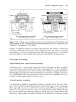
Use of the tundish cover ladle
The most commonly used treatment method, particularly in smaller foundries
is the tundish covered treatment ladle. The principle is shown in Fig. 6.1c.
The use of a refractory dividing wall to form an alloy pocket in the bottom
of the ladle gives improved Mg recovery compared to a pocket recessed in
the bottom of the ladle. Treatment batches are usually in the range, 450–
1000 kg. Figure 6.2 shows the design of a ladle suitable for the treatment of
about 450–500 kg of iron. The diameter of the filling hole is chosen to minimise
the generation of fume while allowing the ladle to be filled quickly without
excessive temperature loss. It is essential that the MgFeSi alloy is not exposed
to the liquid iron until quite late in the filling procedure, so the filling hole
is positioned to introduce liquid iron away from the alloy pocket in the
ladle bottom. The Mg alloy in the alloy pocket is covered with steel turnings
or FeSi pieces of size 25 × 6 mm, then when the level in the ladle reaches the
dividing wall, iron flows over and forms a semi-solid mass with the cover
material allowing the ladle to be almost filled before the reaction starts, thus
ensuring good recovery of Mg.
In order to minimise temperature losses during treatment, the ladle and
cover should be separately heated with gas burners before assembly.
Immediately before use, the ladle should be filled with base iron from the
melting furnace and allowed to soak for a few minutes before returning the
iron to the furnace. The prescribed weight of MgFeSi alloy is charged through
76
Foseco Ferrous Foundryman’s Handbook
the alloy charging tube which is plugged after removal of the charging
funnel. The treatment alloy may be any of the MgFeSi alloys with Mg in the
range 3–6%, additions of 1.5–3.0% are made giving Mg additions of 0.08–
0.15%. Tapping time is usually around 40 seconds.
The temperature loss during treatment is around 50°C, so the tapping
temperature must be adjusted accordingly, treatment temperatures of around
1530°C are commonly used. After treatment, the tundish cover is removed,
the metal transferred to a pouring ladle where inoculation may take place,
then it is cast.
Figure 6.2
Plan and cross-section of tundish/cover Iadle. (From Anderson, J.V.
and Benn, D. (1982)
AFS Trans,
90, 159–162.)
Alloy feed pipe
φ
= 75 mm
(removable cap)
φ
38 mm
203 mm
584
241
100
610
All dimensions in mm
203
φ
= 444
Liquid iron level at 1000 lbs
(455 kg)
Cover material
MgFeSi alloy
Ductile iron
77
Sandwich treatment
A popular method of treatment, frequently used in smaller foundries, is the
sandwich method (Fig. 6.1a). This is essentially the same as the tundish-
cover method but carried out in an open ladle. The magnesium alloy is
placed in a pocket in the bottom of the ladle and covered with steel scrap
(2–3% of the metal weight) or a steel plate. The molten metal stream is
directed away from the pocket. The pocket must be deep enough to contain
all the alloy and the steel scrap which should be of small size to produce a
high packing density. The treatment ladle is usually deep, with a height-to-
diameter ratio of 1.5–2.0 :1, the extra metal depth increases the recovery of
the magnesium, which can be as high as 50% when a 5%Mg alloy is used.
NODULANT
NODULANT briquettes are essentially formed of pure magnesium and
sponge iron. They contain 10% Mg and minor quantities of calcium, cerium,
silicon and carbon. The briquettes weigh between 16 and 20 g and have a
density of 4.3–4.5 g/ml, so they are suitable for use in the sandwich or
tundish cover technique in just the same way that MgFeSi is used. Magnesium
yields are around 40%. The major advantage of using NODULANT is that
a negligible amount of silicon is added during the treatment. This permits
the use of higher silicon in the base iron enabling all the available ductile
iron returns to be used in the charge. By increasing the base silicon, the
lining life of the induction furnace is increased by as much as 40%.
Pure magnesium converter process
The Georg Fischer converter (Fig. 6.1e), has a reaction chamber formed by
a graphite-clay plate of semi-circular section set into the lining of the converter.
Molten iron is charged with the converter in the horizontal position. The
reaction chamber is charged with pure Mg lumps and other additives (if
required) and sealed with a locking stopper. The converter spout is closed
by a pneumatically operated lid. The vessel is then tilted to vertical allowing
a limited amount of metal to enter through holes in the chamber and react
with the magnesium which starts to vaporise. The vapour pressure in the
reaction chamber rises slowing the further entry of liquid iron and allowing
controlled treatment of the contents of the converter. Treatment takes 60–90
seconds. The melt is first deoxidised then desulphurised. When the sulphur
content has dropped to less than 0.002%, the melt starts to absorb magnesium.
Magnesium recovery can be as high as 70%. Base irons with high sulphur
contents of 0.2–0.3%S can be used because of the high efficiency of Mg use.
The standard converter allows up to 2.5 tonnes of iron to be treated 6–8
78
Foseco Ferrous Foundryman’s Handbook
times per hour. Larger units with capacity up to 10 tonnes are available. The
reaction chamber wall has a limited life of 200–800 treatments. Temperature
loss is 22–33°C in a 1-tonne converter but less in larger converters. Since no
Si is added during treatment, an unlimited amount of ductile iron returns
can be used.
The process is operated under licence from Disa Georg Fischer.
Cored-wire treatment
The equipment and principle of the method is shown in Fig. 6.1f which
shows the Foseco IMPREX-Station. The treatment station consists of a coil
of hollow mild steel tube filled with Mg metal, a feeding machine, a guide
tube and a ladle with a close fitting lid. On entering the molten metal, the
sheathing of the wire dissolves releasing the core material below the metal
surface. Wires vary in size from 4 mm to 13 mm. The amount of wire needed
is dependent on the sulphur content of the base iron, the temperature of the
iron and the reactivity of the wire used. Once the treatment parameters
have been established, it is a simple matter to calculate the amount of
wire required and the treatment time. Feed details can then be programmed
into a computer. Typical feed rates of 9 mm wire are 30–50 metres per
minute. 1500 kg of metal can be treated in about 2 minutes. Treatment
temperature starts at around 1450°C, dropping to around 1410°C at the
finish.
In-the-mould treatment
It is possible to carry out the nodularising treatment in the mould by
incorporating a specially designed magnesium treatment chamber in the
gating system into which the treatment alloy is placed (Fig. 6.1g). The gating
method must fill with metal as quickly as possible and must maintain constant
flow conditions so that all the metal, from first to last, is equally treated.
Since treatment of iron with Mg always produces some MgO and MgS
dross, care must also be taken to avoid dross entering the casting. This is not
easy to achieve and requires a good deal of experimentation so the method
is generally only used by large repetition foundries, which are able to devote
considerable time to solving the process problems.
Inhibiting elements
Certain elements which may be present in the base iron have an inhibit-
ing effect on nodule formation, the following elements are known to be
harmful:
Ductile iron
79
Aluminium above 0.13%
Arsenic above 0.09%
Bismuth above 0.002%
Lead above 0.005%
Tin above 0.04%
Titanium above 0.04%
Antimony, tellurium and selenium are also harmful. The combined effect of
two or more of these elements may be even more harmful. The addition of
cerium and other rare earth elements, together with calcium will neutralise
many of the harmful effects of inhibiting elements and most MgFeSi
nodularising alloys contain 0.3–1.0% Ce and other rare earths. 0.5–1.0% Ca
is also commonly present.
Inoculation and fading
Immediately after treatment, the iron must be inoculated. Larger additions
of inoculant are needed compared with grey iron and from 0.5–0.75% of a
graphitising inoculant such as INOCULIN 25 should be used. Inoculation
treatment is not permanent, the effect begins to fade from the time the
inoculant is added. As the inoculating effect fades, the number of nodules
formed decreases and the tendency to produce chill and mottle increases. In
addition the quality of the graphite nodules deteriorates and quasi-flake
nodules may occur.
When inoculating ductile iron, the inoculant must be added after the
magnesium flare has subsided. A common practice is to tap about half the
metal onto the magnesium alloy and wait for the flare to finish before adding
the inoculant to the tapping stream as the rest of the metal is tapped. If the
metal is transferred from the treatment ladle to a casting ladle, an effective
practice is to make a further small addition of inoculant as the metal is
poured into the casting ladle. About 0.1–0.2% of inoculant is adequate.
Significant fading occurs within five minutes of inoculation. Because of
this problem, late stream or mould inoculation is commonly used in ductile
iron production, see p. 68.
Specifications for ductile cast iron
Table 6.1 lists a number of national and international specifications for ductile
iron, it is necessary to consult the original specifications for details of the
methods of testing and the mandatory values that must be achieved. In
recent years, specifications in different countries have been converging so
they are now all quite similar. Table 6.2 lists the suggested chemical
compositions required to produce castings that meet the specifications in
the as-cast state.
Table 6.1 Specifications for ductile (nodular) cast irons
Country Minimum tensile strength/elongation
Specification (N/mm
2
/%)
Europe EN-GJS- 350-22 400-18 400-15 450-10 500-7 600-3 700-2 800-2 900-2
CEN 1563:1997
UK* BS2789 350/22 400/18 420/12 450/10 500/7 600/3 700/2 800/2 900/2
1985
USA ASTM A536 60-40-18 60-42-10 65-45-12 70-50-05 80-55-06 80-60-03 100-70-03 120-90-02
1993
Japan JIS FCD 350-22 400-18 400-15 450-10 500-7 600-3 700-2 800-2
G5502
1995
Inter- ISO 1083 350-22 400-18 400-15 450-10 500-7 600-3 700-2 800-2 900-2
national 1987
Hardness
Typical HB <160 130-175 135-180 160-210 170-230 190-270 225-305 245-335 270-360
Typical F F F F & P F & P F & P P P or T TM
structures
Notes: The European CEN 1563 Standard also specifies 350-22-LT and 400-18-LT for low temperatures.
350-22-RT and 400-18-RT for room temperature.
*BS2789 has been withdrawn and replaced by EN1563:1997.
The designations of US Standards e.g. 100-70-03, refers to min. tensile strength(lbf/in
2
)-min. proof stress-elongation %.
The structures are: TM, tempered martensite; P or T, pearlite or tempered structure; P & F, pearlite and ferrite; F, ferrite.
This Table is intended only as a guide, refer to the National Standards for details.
Table 6.2 Suggested analyses for as-cast production of ductile iron
Average Grades Grade Grade Grade
casting 800/2,700/2,600/3 500/7 400/12 400/18
section TC Si Mn(max) TC Si Mn(max) TC Si Mn(max) TC Si Mn(max)
<13 mm 3.6–3.8 2.6–2.8 0.5 3.6–3.8 2.6–2.8 0.3 3.6–3.8 2.6–2.8 0.2 3.6–3.8 2.6–2.8 0.1
13–25 3.5–3.6 2.2–2.5 0.6 3.5–3.6 2.2–2.5 0.35 3.5–3.6 2.2–2.4 0.25 3.5–3.6 2.2–2.4 0.15
25–50 3.5–3.6 2.1–2.3 0.7 3.5–3.6 2.1–2.4 0.4 3.5–3.6 2.2–2.4 0.3 3.5–3.6 2.2–2.4 0.20
50–100 3.4–3.5 1.9–2.1 0.8 3.4–3.5 2.0–2.2 0.5 3.4–3.5 2.0–2.2 0.35 3.4–3.5 1.8–2.0 0.2
>100 3.4–3.5 1.8–2.0 0.8 3.4–3.5 1.8–2.0 0.6 3.4–3.5 1.8–2.0 0.40 3.4–3.5 1.8–2.0 0.25
Notes: For the higher strength grades, 800,700,600, additions of 0.5% Cu or 0.1% Sn may be made to encourage pearlite formation.
In all grades: Phosphorus should be less than 0.05%
Chromium should be less than 0.05%
Residual Mg should be 0.03
–0.06%
82
Foseco Ferrous Foundryman’s Handbook
Heat treatment of ductile iron
It is obviously desirable to achieve the required properties in the as-cast
form, but this is not always possible because of variations of section thickness
etc. Heat treatment of the castings will eliminate carbides in thin sections,
produce more consistent matrix structures and for a given structure, the
mechanical properties are often improved by heat treatment, especially by
normalising. Where tempered martensite structures are needed, heat treatment
is essential.
Stress relief
Heat at 50–100°C/h to 600°C (taking care not to exceed 610°C), soak for one
hour plus an hour for every 25 mm of section thickness in the thickest
section. Cool at 50–100°C/h to 200°C or less. Ensure that the castings are
adequately supported in the furnace so that they are not subjected to stress.
Breakdown of carbides
Thin section castings may contain carbides in the as-cast structure, these
can be eliminated by soaking the castings at 900–925°C for 3 to 5 hours.
Annealing to produce a ferritic matrix
Castings should be soaked at 900–925°C for 3–5 hours, followed by slow
cooling at around 20–35°C/h through the critical temperature (about 800–
710°C), then furnace cooled at, say 50–100°C/h to 200°C.
Normalising to produce a pearlitic matrix
Soak the castings above the critical temperature then air cool. Again a soaking
temperature of 900–925°C is usually used, to ensure that carbides are broken
down, then use forced air cooling to form pearlite. The type of heat treatment
furnace available and the size of the load determines the cycle that is possible.
It may be necessary to adjust the metal composition with tin or copper to
help the formation of fully pearlitic structures.
Hardened and tempered structures
Austenitise at 900–920°C then oil quench. Tempering is usually carried out
at 600–650°C.
Ductile iron
83
Austempered ductile iron (ADI)
Austempering is an isothermal heat treatment for producing ‘bainitic’
structures. It can double the strength of ductile iron while retaining good
ductility and toughness. Wear resistance and fatigue properties are excellent
so that ADI is comparable with wrought steel.
The ADI heat treatment is a two-stage process, shown in Fig. 6.3.
Austenitising is carried out at 815–930°C to fully transform the matrix to
austenite. This is done either in a non-oxidising atmosphere furnace or in a
high temperature salt bath, temperatures and times are determined by
chemical composition, section size and grade of ADI required. 1 to 1.5 hours
is usually adequate. Slow initial heating of the casting is desirable to avoid
the danger of cracking of complex shapes. The castings are then quenched
to the required isothermal heat treatment temperature, usually between 210
and 400°C. This is usually done in a salt bath (Fig. 6.3). The castings are held
at temperature for 1–2 hours to complete the transformation of austenite to
bainite. The lower temperatures give high hardness, strength and wear
resistance, while the higher heat treatment temperatures result in higher
ductility and toughness. After the isothermal treatment, the castings are
cooled to ambient temperature.
Unalloyed ductile irons may be austempered in sections up to about
8 mm. Thicker section castings require the addition of Mo or Ni to increase
the hardenability.
Typical changes in properties due to austempering of an unalloyed iron are:
As-cast Austempered 1h Austempered 1h
at 300
°
C at 375
°
C
Tensile strength (N/mm
2
) 475 1465 1105
Elongation (%) 19 1 9
Hardness (HB) 160 450 320
Austempered ductile iron finds applications as a replacement for forged
steel components in the agricultural, mining, automotive and general
engineering industries; for example: plough tips, digger teeth, spring brackets,
rear axle brackets, gears etc. ADI production is growing but its use is limited
to some extent by the lack of suitable heat-treatment facilities.
The European/British Specification BS EN 1564:1997 defines four grades
of ADI, Table 6.3.
Table 6.3 European grades of ADI
Material designation Tensile 0.2%PS Elongation Hardness
strength (MPa) (MPa) (%) (HB)
EN-GJS-800-8 800 500 8 260–320
EN-GJS-1000-5 1000 700 5 300–360
EN-GJS-1200-2 1200 850 2 340–440
EN-GJS-1400-1 1400 1100 1 380–480
84
Foseco Ferrous Foundryman’s Handbook
Mechanical properties are measured on test pieces machined from
separately cast test pieces.
In North America, the ASTM has defined five standard grades of ADI,
Table 6.4.
Table 6.4 The five ASTM standard ADI grades (ASTM A897M-90)
Grade TensiIe* Yield* Elongation* Impact Typical
strength strength (%) energy* hardness
(MPa) (MPa) (Joules) (BHN)
1 850 550 10 100 269–321
2 1050 700 7 80 302–363
3 1200 850 4 60 341–444
4 1400 1100 1 35 388–477
5 1600 1300 N/A N/A 444–555
*Minimum values
Casting ductile iron
Ductile iron differs from grey iron in its casting characteristics in two important
respects. Unlike grey iron, ductile iron is a dross-forming alloy. The residual
magnesium which is needed to ensure nodular graphite formation rapidly
oxidises whenever the liquid metal is exposed to air; in the ladle, during
metal transfer and in the mould. A magnesium silicate dross is formed
which may give rise to defects at or just below the casting surface, usually
on the upper surfaces of the castings. For this reason, it is common practice
to filter ductile iron castings through ceramic filters, see Chapter 18.
The other major difference compared with grey iron, is the need to feed
ductile iron castings to ensure freedom from shrinkage defects. Ductile irons
always have a high carbon equivalent so the volume of graphite precipitated
during solidification should ensure completely sound sections. However,
the expansion resulting from the graphite precipitation results in large
pressures being exerted on the mould walls, much higher than those found
with grey iron (figures of 1000–1500 kPa or 145–217 lbf/in
2
have been
measured compared with 170–200 kPa or 24–29 lbf/in
2
in grey iron). Only
the strongest moulds, such as sodium silicate bonded moulds or well-vibrated
lost foam moulds, will resist such pressures so the use of feeders is common
when ductile iron castings are made.
Compacted graphite irons
Compacted graphite (CG) irons are a range of cast irons having mechanical
properties intermediate between those of grey and ductile irons. Under the
microscope the graphite appears as short, thick flakes with rounded ends,
readily distinguished from true flake graphite (Fig. 6.4). Compacted graphite
Ductile iron
85
is interconnected in a branched structure, and is more like flakes than the
completely isolated nodules in ductile iron. Compacted graphite is not the
same as vermicular graphite which can occur in irons of very low sulphur.
Compacted graphite iron has good casting characteristics, due to its high
fluidity and low solidification shrinkage. The tensile, yield and fatigue
strengths of CG iron are 1.5–2 times that of grey iron, approaching ductile
iron. Thermal conductivity is comparable with grey iron and machinability
1000
800
600
400
200
Temperature °C
0 12 345678
Time hr
Typical austempering heat treatment stages
Grade 4
AD1
Grade 1
AD1
930°C
815°C
400°C
(260–320 BHN)
230 °C
2
1
/
2
hr max
(400–500 BHN)
Figure 6.3
Typical austempering heat-treatment stages. (R.D. Forrest, 13th DISA/
GF Licensee Conference 1997. Courtesy Rio Tinto Iron and Titanium GmbH.)
Figure 6.4
Structure of compacted graphite. (Courtesy SinterCast.)
CGI microstructure100 µ m
86
Foseco Ferrous Foundryman’s Handbook
is intermediate between grey and ductile irons of similar matrix structures.
This combination of properties makes CG iron suitable for upgrading of
castings traditionally produced of grey iron.
Production of compacted graphite iron
There are several methods by which compacted graphite may be produced:
Cerium additions
Magnesium additions
Nitrogen additions
Magnesium plus titanium additions
One method involves the joint addition of a nodularising and a de-
nodularising agent, usually magnesium and titanium often with a small
cerium addition as well. Special treatment alloys have been developed for
the production of CG iron.
Mg Ti Ce Ca Al Si Fe
4.5–5.5 8.0–10.0 0.3–0.4 1.0 max 1.5 max 50–54 balance
As with ductile iron, it is desirable to start with a low sulphur iron, below
0.02%. The base iron for treatment is best melted in an induction furnace
and should have composition in the range:
CE C Si Mn S P
3.7–4.5 3.1–3.9 1.7–2.9 0.1–0.6 0.035 max 0.06 max
A sandwich technique may be used with addition rates between 0.6–1.6%
depending on the foundry conditions. The treatment temperature should
be above 1350°C to avoid the formation of a fully nodular structure. Inoculation
of the treated iron is necessary and additions of 0.2–0.5% ferrosilicon are
common. The matrix structure may be made ferritic or pearlitic as with
ductile iron. Titanium-containing alloys can cause problems due to build-
up of Ti in foundry returns leading to impaired machinability.
The use of compacted graphite iron was limited for many years by the
difficulty foundries experienced in controlling the process within the narrow
range of CGI stability so it was considered an unreliable material.
A Swedish company, SinterCast, has developed a method of process
control for CGI which allows CGI to be made reliably. The process can be
licensed by foundries. Figure 6.5 represents the transition of graphite
morphology from flake to compacted and ultimately to spheroidal graphite
as a function of Mg content. This suggests that a range of 0.005–0.010% total
Mg will cause formation of compacted graphite. This curve does not fully
account for reactions between Mg and dissolved elements in the iron,
particularly oxygen and sulphur. Figure 6.6 illustrates by deep etched scanning
Ductile iron
87
Figure 6.6
The transition of graphite morphology from flake to compacted to
spheroidal shown by deep etched scanning electron micrographs.
(Courtesy SinterCast.)
Grey iron to ductile iron transition
Ductile iron
100
80
60
40
20
0
% Nodularity
CGI
Grey
0.010 0.020 0.030 0.040 % Total Mg
Figure 6.5
The effect of total Mg content on the transformation of graphite morphology
from flake to compacted and ultimately to spheroidal graphite. (Courtesy SinterCast.)
electron micrographs, the transition of graphite morphology from flake to
compacted to spheroidal. The SinterCast Process involves taking a sample
of liquid iron from the ladle in a patented sampling cup and carrying out a
thermal analysis using two thermocouples, one in the centre of the cup and
the other adjacent to the wall. The two cooling curves allow the degree of
modification and inoculation required to be determined. Independent
additions of cored wire containing Mg and inoculant are then made to the
ladle. Ladle to ladle variations in the oxygen and sulphur content of the iron
are thus allowed for and reliable compacted graphite iron is made.
88
Foseco Ferrous Foundryman’s Handbook
Foundry properties of compacted graphite iron
The fluidity is governed by carbon equivalent (CE) and temperature and is
similar to grey or ductile irons of the same CE. Because CG irons are stronger
than grey irons, a higher CE can be used to obtain the same strength, this
allows greater fluidity and easier running of thin sections. CG iron is dross-
forming, just as ductile iron, and filtration of castings is desirable. CG irons
are more prone to chill than grey irons but less likely to chill than ductile
iron. Good inoculation is necessary. Fading occurs, but to a smaller extent
than in ductile iron, but excessive delays between treatment, inoculation
and casting should be avoided.
There is some disagreement about the level of feeding required for CG
iron. There is less tendency for mould wall movement than with ductile
iron, nevertheless some feeding appears to be desirable.
Applications of compacted graphite irons
There has been great interest in its use for automotive castings such as
diesel cylinder blocks and heads, hydraulic components, exhaust manifolds,
brake drums, brake discs, flywheels etc. The lack of consistency of properties
held back the wide scale application of CG iron but with the greater control
now possible its use is expected to develop.
Properties of compacted graphite irons
Table 6.5 Comparison of CG iron properties with grey and ductile irons
Property Grey irons CG irons Ductile irons
Tensile strength
ton/in
2
11–20 20–38 26–45
lb/in
2
25–45 000 45–85 000 60–100 000
kg/mm
2
16–32 30–60 40–70
N/mm
2
160–320 300–600 400–700
Elongation (%) nil 3–66–25
Modulus (lb/in
2
)14–16×10
6
20–23×10
6
25–27×10
6
(GN/m
2
)96–110 140–160 170–190
Charpy impact
Joules, 25°C nil 3–717
Fatigue limit
un-notched (ton/in
2
)7–815–20 12–18
(N/mm
2
) 108–123 230–310 185–280
Machinability very good very good good
Corrosion moderate intermediate good
resistance
Ductile iron
89
Table 6.6 Specifications for compacted graphite iron: ASTM A842-85 (reapproved
1991) compacted graphite iron
Grade
250
a
300 350 400 450
b
Tensile strength (MPa) 250 300 350 400 450
Yield strength (MPa) 175 210 245 280 315
Elongation (%) 3.0 1.5 1.0 1.0 1.0
Hardness (HB) 179 max 143–207 163–229 197–225 207–269
a
ferritic grade
b
pearlitic
Hardness not mandatory