Foseco Ferrous Foundryman''''s Handbook Part 3 docx
Bạn đang xem bản rút gọn của tài liệu. Xem và tải ngay bản đầy đủ của tài liệu tại đây (295.24 KB, 25 trang )
Chapter 4
Melting cast irons
Introduction
Iron foundries require metal of controlled composition and temperature,
supplied at a rate sufficient to match the varying demands of the moulding
line. The metallic charge to be melted consists usually of foundry returns,
iron scrap, steel scrap and pig iron with alloying additions such as ferrosilicon.
The charge is usually melted in a cupola or in an electric induction furnace.
Gas-fired or oil-fired rotary furnaces can also be used, but their use is less
common.
Cupola melting
The cupola (Fig. 4.1) is the classical iron melting unit and is still the most
widely used primary melting unit for iron production due to its simplicity,
reliability and the flexibility in the quality of charge materials that can be
used because some refining of undesirable elements such as zinc and lead
can be achieved. While the cupola is an efficient primary melting unit, it
does not adapt easily to varying demands, nor is it an efficient furnace for
superheating iron. For this reason it is often used in conjunction with an
electric duplexing furnace.
The simplest form is the cold blast cupola which uses ambient temperature
air to burn the coke fuel. The metal temperature that can be achieved is
normally from 1350 to 1450°C but higher temperatures can be achieved
through the use of divided blast (as in Fig. 4.1) or oxygen enrichment. The
refractory linings of cold blast cupolas have a short life of less than 24
hours, so cupolas are operated in pairs, each used alternately while the
other is re-lined.
In hot blast cupolas (Fig. 4.2), the exhaust gases are used to preheat the
blast to 400–600°C, reducing coke consumption and increasing the iron
temperature to more than 1500°C. They may be liningless or use long life
refractories giving an operating campaign life of several weeks.
‘Cokeless’ cupolas (Fig. 4.3), have been developed in which the fuel is
gas or oil with the charge supported on a bed of semi-permanent refractory
spheres. They have advantages of reduced fume emission.
Melting cast irons
41
Cold blast cupola operation
The cupola is charged with:
1. coke, the fuel to melt the iron;
2. limestone, to flux the ash in the coke etc.;
3. metallics, foundry scrap, pig iron, steel and ferroalloys;
4. other additions to improve the operation
Charging
door
Metal and
coke charge
Blast air
Blast air
Slag
Sand bed
Tuyéres
Melting
zone
Iron
Figure 4.1
Section through a cupola
(
From ETSU Good Practice Case Study 161;
courtesy of the Department of the Environment, Transport and the Regions
.)
42
Foseco Ferrous Foundryman’s Handbook
The cupola is blown with air to combust the coke and the air flow controls
the melting rate and metal temperature. The output of a cupola depends
primarily on the diameter of the shaft of the furnace and on the metal/coke
ratio used in the charge. Table 4.1 summarises the operating data for typical
cold blast cupolas.
A useful measure of the efficiency of operation of a cupola is the ‘Specific
Coke Consumption’ (SSC) which is
Annual tonnage of coke 1000
Annual tonnage of metallics charged
= SSC (kg/tonne)
×
This takes into account both charge coke and bed coke. When the cupola is
operated for long enough campaigns, the amount of coke used to form the
bed initially can be ignored. However, as the melting period decreases, the
role of the cupola bed becomes more important. Table 4.2 summarises data
from 36 cupola installations in the UK in 1989. This table provides a useful
reference against which the operation of any cold blast cupola can be
compared.
Coke
The performance of the cupola is highly dependent on the quality of the
coke used. Typical foundry coke has the following properties:
Moisture 5% max.
Ash 10% max.
CUPOLA HEAT EXCHANGER DUST COLLECTOR CHIMNEY
Figure 4.2
Hot blast cupola
. (
From ETSU Good Practice Case Study 366; courtesy
of the Department of the Environment, Transport and the Regions.
)
Melting cast irons
43
Volatiles 1% max.
Sulphur 1% max.
Mean size 100 mm
Undersize <5% below 50 mm
The coke size directly affects coke consumption per tonne of iron melted
and also the melting rate. Optimum cupola performance is achieved with
coke in the size range 75–150 mm, if smaller coke is used, metal temperature
is reduced and a higher blast pressure is needed to deliver the required
amount of air to the cupola. Increasing the size of coke above about 100 mm
has no beneficial effect, probably because large pieces of coke tend to be
fissured and break easily during charging and inside the cupola.
Coke usage in the cold blast cupola is typically 140 kg per tonne of iron
melted (this is an overall figure including bed coke), it is usual to charge
coke at the rate of about 10–12% of the metal charged, but the exact amount
used depends on many factors such as tapping temperature required, melting
rate and the design of the cupola, see Table 4.2.
Charge opening
Air pipe
Blast inlet
Charge
Shell cooling
Ceramic
bedding
Water-cooled grate
Burner
Siphon with slag separator
Carburization
Temperature measuring instrument
Superheater
Deslagging
opening
Tap hole
Inductor
Feeder
Tilting cylinder
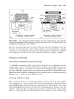
Figure 4.3
Schematic diagram of a cokeless cupola in a duplex system
.
(
From R.F. Taft,
The Foundryman, 86,
July 1993 p. 241.
)
Table 4.1 Cupola operation data
Metric units
Diameter Melting rate (tonnes/h) Blast Typical charge (kg) Bed height Shaft height (m)
of melting metal:coke ratio rate pressure at 10:1 coke rate above tuyeres tuyeres to
zone (cm) 10 : 1 8:1 m
3
/h cm H
2
O kPa coke iron limestone (cm) charge door sill
50 1.97 1.57 1340 104 10.2 20 200 7 100 2.5
60 2.84 2.46 1940 107 10.5 28 284 9 100 3.0
80 5.11 4.36 3450 114 11.2 51 510 17 105 3.0
100 7.99 6.83 5380 119 11.7 80 800 26 105 3.5
120 11.50 9.79 7750 130 12.7 115 1150 38 110 4.0
140 15.60 13.33 10 600 137 13.4 157 1570 52 110 4.0
160 20.44 17.41 13 800 147 14.4 200 2040 67 110 4.5
180 25.88 22.05 17 450 157 15.4 260 2590 85 115 5.0
200 31.95 27.22 21 550 175 17.2 320 3200 106 115 5.0
Table 4.1 (Continued)
Imperial units
Diameter Melting rate (ton/h) Blast Typical charge (lbs) Bed height Shaft height (feet)
of melting metal:coke ratio rate pressure at 10:1 coke rate above tuyeres tuyeres to
zone (inches) 10:0 8:1 cfm in. w.g. coke iron limestone (inches) charge door sill
18 1.6 1.3 665 40 36 360 12 38 16
24 2.9 2.5 1180 42 65 650 21 39 16
30 4.5 3.9 1840 44 100 1000 33 41 16
36 6.6 5.6 2650 46 150 1500 50 41 19
42 9.0 7.6 3620 48 200 2000 66 42 19
48 11.7 10.0 4720 51 260 2600 86 42 22
54 14.8 12.6 5950 53 330 3300 109 43 22
60 18.3 15.6 7360 57 410 4100 135 43 22
66 22.1 18.8 8900 60 500 5000 165 44 22
72 26.5 22.5 10 650 63 594 5940 196 44 22
78 31.1 26.4 12 500 69 697 6970 230 44 22
84 36.1 30.6 14 500 75 809 8090 267 45 22
The above figures represent good average practice and are intended to act as a rough guide only.
Table 4.2 Data for cupolas in the UK (1989)
Melt rate Cupola Water Tapping Melt Bed coke Restore SCC Type of % Coke Divided
(t/hr) dia. (inches) cooled? temp. (°C) period (hrs) (kg) coke (kg) (kg/tonne) metal charge blast
1.5 22.0 no 1400 1.5 100 407 grey 12.00
2.0 36.0 1500 3.5 500 252 grey 14.00
3.0 30.0 no 1300 3.0 500 260 grey 4.00
3.0 32.0 1340 2.0 600 150 216 grey 8.9
3.0 32.0 no 1450 7.0 500 60 133 malleable 11.00
3.0 36.0 yes 1350 3.0 400 150 313 grey 16.00
3.0 22.0 2.0 100 267 grey 20.00
3.0 30.0 yes 1450 9.0 210 100 grey
3.0 26.0 1550 2.0 242 grey
3.0 30.0 no 1475 7.5 490 0 214 malleable 16.00
3.0 30.0 no 1430 2.0 400 150 grey 7.20
3.0 30.0 no 1480 7.0 700 140 208 grey 15.00
3.5 33.0 yes 1300 3.0 380 212 grey 18.00
4.0 33.0 no 1450 6.0 1750 grey 9.00
4.0 35.0 no 1450 3.0 600 217 grey 12.00 x
4.0 36.0 no 1470 3.5 650 150 105 grey 7.00
4.0 30.0 no 1500 5.0 840 500 211 grey 12.00
4.0 34.0 no 1460 3.0 375 127 grey 12.4
(Contd)
4.5 31.0 1550 10.0 1000 86 164 grey 13.50
5.0 32.0 no 1530 8.0 600 129 grey 12.5
5.0 33.0 no 1550 4.0 750 243 grey 16.0 x
5.0 36.0 no 1470 8.0 1750 250 178 grey 17.80 x
5.0 36.0 no 1500 2.0 420 144 grey 100.00
5.0 39.0 no 1460 8.0 450 150 171 grey 11.00 x
8.0 42.0 no 1500 4.0 1500 153 grey 11.00
8.0 53.9
8.0 48.0 yes 1550 9.0 900 363 140
8.0 38.0 no 1490 7.0 1100 115 grey 8.64 x
8.0 48.0 no 1440 8.0 1500 138 grey wide range
9.0 42.0 yes 1500 33.0 2000 180 121 grey 10.60 x
9.5 48.0 yes 1460 8.0 1000 500 129 grey 10.0 x
10.0 52.0 no 1450 8.0 1800 400 154 grey 13.10
10.0 48.0 yes 1500 15.0 1800 300 138 grey 13.70 x
12.0 48.0 1520 8.5 1800 300 112 grey 9.50 x
12.0 43.0 yes 1530 20.0 1200 200 104 malleable 9.50 x
20.0 72.0 yes 1550 336.0 4000 169 duct 16.50
From: Coke consumption in iron foundry cupolas, Energy of Consumption Guide 7, November 1990, reproduced by permission of the Energy Efficiency Office
of the Department of the Environment.
Table 4.2 (Continued)
Melt rate Cupola Water Tapping Melt Bed coke Restore SCC Type of % Coke Divided
(t/hr) dia. (inches) cooled? temp. (°C) period (hrs) (kg) coke (kg) (kg/tonne) metal charge blast
48
Foseco Ferrous Foundryman’s Handbook
Fluxes
Fluxes are added to the cupola charge to form a fluid slag which may easily
be tapped from the cupola. The slag is made up of coke ash, eroded refractory,
sand adhering to scrap metal and products of oxidation of the metallic charge.
Limestone is normally added to the cupola charge, it calcines to CaO in the
cupola and reacts with the other constituents to form a fluid slag. Dolomite,
calcium–magnesium carbonate, may also be used instead of limestone.
The limestone (or dolomite) should contain a minimum of 96% of CaCO
3
(and MgCO
3
) and should be in the size range 25–75 mm.
The amount of the addition is dependent on the coke quality, the cleanliness
of the charge and the extent of the lining erosion. Normally 3–4% of the
metallic charge weight is used. Too low an addition gives rise to a viscous
slag which is difficult to tap from the furnace. Too high an addition will
cause excessive attack on the refractory lining. When the coke bed is charged,
it is necessary to add around four times the usual charge addition of limestone
to flux the ash from the bed coke.
Other fluxes may also be added such as fluorspar, sodium carbonate or
calcium carbide. Pre-weighed fluxing briquettes, such as BRIX, may also, be
used. BRIX comprises a balanced mixture of fluxing agents which activates
the slag, reduces its viscosity and produces hotter, cleaner reactions in the
cupola. This raises carbon content, reduces sulphur and raises metal
temperature.
Correct additions of flux are essential for the consistent operation of the
cupola and care should be taken to weigh the additions accurately.
The metallic charge
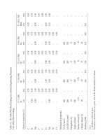
Table 4.3 gives the approximate metal compositions needed for the most
frequently used grades of grey iron. (Data supplied by CDC.)
Table 4.3 Metal composition needed to produce the required grade of grey iron
Grade 150 200 250 300 350
Total carbon (%) 3.1–3.4 3.2–3.4 3.0–3.2 2.9–3.1 3.1 max
Silicon (%) 2.5–2.8 2.0–2.5 1.6–1.9 1.8–2.0 1.4–1.6
Manganese (%) 0.5–0.7 0.6–0.8 0.5–0.7 0.5–0.7 0.6–0.75
Sulphur (%) 0.15 0.15 0.15 max 0.12 max 0.12 max
Phosphorus (%) 0.9–1.2 0.1–0.5 0.3 max 0.01 max 0.10 max
Molybdenum (%) 0.4–0.6 0.3–0.5
Cu or Ni (%) 1.0–1.5
Note: Copper may partially replace nickel as an alloying addition
Metallic charge materials
The usual metallic charge materials are:
Return scrap: runners, risers, scrap castings etc. arising from the foundry
Melting cast irons
49
operation. Care must be taken to segregate each grade of returns if the
foundry makes more than one grade of iron.
Pig iron: being expensive, the minimum amount of pig iron should be
used. Use of pig iron is a convenient way of increasing carbon and silicon
content. Special grades of pig iron having very low levels of residual
elements are available and they are particularly useful for the production
of ductile iron.
Steel scrap: is normally the lowest cost charge metal, it is used for lowering
the total carbon and silicon contents.
Bought scrap iron: care must be taken to ensure that scrap of the correct
quality is used, particularly for the production of the higher strength
grades of iron.
Harmful materials
Care must be taken to ensure that contaminants are not introduced into the
iron. The most common harmful elements are:
Lead, usually from leaded free-cutting steel scrap.
Chromium, from stainless steel.
Aluminium, from aluminium parts in automotive scrap.
Size of metallic charge materials
Thin section steel scrap (below about 5 mm) oxidises rapidly and increases
melting losses. On the other hand, very thick section steel, over 75 mm, may
not be completely melted in the cupola. Metal pieces should be no longer
than one-third of the diameter of the cupola, to avoid ‘scaffolding’ of the
charges.
Ferroalloys
Silicon, manganese, chromium, phosphorus and molybdenum may all be
added in the form of ferroalloys. In some countries, Foseco supplies briquetted
products called CUPOLLOY designed to deliver a specific weight of the
element they introduce, so that weighing is unnecessary.
Ferrosilicon in lump form, containing either 75–80% or 45–50% Si may be
used. Ferromanganese in lump form contains 75–80% Mn. Both must be
accurately weighed before adding to the charge.
Pig irons
Typical pig iron compositions are given in Table 4.4. Refined irons for foundry
50
Foseco Ferrous Foundryman’s Handbook
use are normally made in a hot blast cupola from selected scrap, they may
contain copper, tin, chromium and other alloy elements. Base irons for ductile
(s.g., nodular) iron production are made from specially pure ores, and have
very low residual element contents. They are available in a range of
specifications.
Table 4.4 Foundry pig iron
Grade Typical composition
TC(%) Si(%) Mn(%) S(%) P(%)
Blast furnace irons 3.4–4.5 0.5–4.0 0.7–1.0 0.05 max 0.05 max
Refined irons 3.4–3.6 0.75–3.5 0.3–1.2 0.05 max 0.1 max
Ductile base irons 3.8 0.05–3.0 0.01–0.20 0.02 max 0.04 max
Purchased cast iron scrap is available in a number of grades, typical
compositions are shown in Table 4.5.
Table 4.5 Cast iron scrap
Type Typical composition
TC(%) Si(%) Mn(%) S(%) P(%)
Ingot mould scrap 3.5–3.8 1.4–1.8 0.5–1.0 0.08 0.1
Heavy cast iron scrap 3.1–3.5 2.2–2.8 0.5–0.8 0.15 0.5–1.2
Medium cast iron scrap 3.1–3.5 2.2–2.8 0.5–0.8 0.15 0.5–1.2
Automobile scrap 3.0–3.4 1.8–2.5 0.5–0.8 0.15 0.3 max
Typical charges needed to produce the most frequently used grades of iron
are given in Table 4.6.
Table 4.6 Typical furnace charges
Grade 150 Grade 200 Grade 250
25% pig iron 30% low P pig iron 25% low P pig iron
40% foundry returns 35% foundry return 35% foundry returns
30% bought cast iron 20% low P cast iron scrap 15% low P scrap
5% steel scrap 15% steel scrap 25% steel scrap
Cupola charge calculation
In a normally operated, acid cold blast cupola, the composition of the metal
tapped can be predicted with reasonable accuracy from the composition of
the furnace charge. The tendency is for the total carbon to attain the eutectic
equivalent. If the quantity charged is above this value, a loss may be expected.
On the other hand, where the charge contains less than the eutectic value,
the trend is towards a carbon pick-up. The exact amount of carbon change
must be established by experience for a particular cupola operation, but the
following ‘Levi equation’ is a good starting guide.
Melting cast irons
51
TC% at spout = 2.4 +
TC% in the charge
2
–
Si% + P% at spout
4
Silicon is always lost in the cupola, generally a loss of 15% of that charged
may be assumed, but higher losses may occur if high steel charges are used.
Manganese losses are usually about 25%. Phosphorus changes little. Sulphur
always increases due to pick-up from the coke, but the precise amount
cannot be predicted and must be based on experience.
Based on these guide lines, a calculation may be made as follows:
To make a Grade 250 iron with the composition:
TC Si Mn P
3.2 1.7 0.7 0.1
Material Amount Composition Contribution to charge (%)
charged TC Si Mn P TC Si Mn P
(%)
Low-P pig iron 25 3.0 3.0 1.0 0.1 ×0.25 0.75 0.75 0.25 0.03
Grade 250 returns 35 3.2 1.7 0.7 0.1 ×0.35 1.12 0.60 0.25 0.04
Low-P scrap iron 15 3.2 2.2 0.8 0.15 ×0.15 0.48 0.33 0.12 0.02
Steel scrap 25 0.1 0.1 0.3 0.03 ×0.25 0.03 0.03 0.08 –
Ferromanganese 0.3 75 ×0.003 0.23
Total 2.38 1.71 0.93 0.09
Changes during melting Si loss 15% –0.26
Mn loss 25% –0.23
Addition at spout 70% ferrosilicon +0.25
Expected composition T.C. = 2.4 + 2.38/2 – (1.45 + 0.09)/4
= 3.2
Si = 1.70
Mn = 0.70
P = 0.09
Calculations such as the above example, should only be used as a guide.
The precise carbon pick-up and silicon losses achieved depend on factors
such as coke quality, metal temperature, melting rate etc. Experience will
enable more accurate predictions to be made. A number of computer programs
are available which carry out the calculations rapidly and enable ‘least cost’
charges to be selected.
Cupola output
The maximum output from a cupola is determined primarily by the shaft
diameter, Table 4.1. In normal use, it is necessary to be able to vary the output
to match the requirements of the moulding line. This is done by varying the
blast rate. Increasing or reducing the air supplied to the cupola burns more
or less coke and increases or reduces the melting rate. Unfortunately, changing
the blast rate also changes the temperature of the metal, and to some extent,
52
Foseco Ferrous Foundryman’s Handbook
its composition. This is one of the main drawbacks of the cupola as a melting
furnace. Another problem is that the only way of changing the composition
of the liquid iron is to change the make-up of the charge, and it usually takes
around an hour before the change is seen at the tap-hole. To overcome these
difficuties, it is common practice to tap the cupola into an electric holding
furnace where the temperature and composition can be accurately controlled,
and variations in metal demand can be accommodated.
Emissions from cupolas
Exhaust gases from cupolas are hot and contain dust, grit and SO
2
gas. For
many years, the emissions permitted from cold blast cupolas were readily
achieved by the use of simple wet arresters. The cupola gases pass through
a curtain of water which removes the grit particles, absorbs up to half of the
SO
2
but does not remove dust. Present day environmental regulations in
most countries impose increasingly strict limitations on the dust emissions
permitted from cupolas, requiring additional dust-arresting plant to be fitted.
Wet scrubbers, bag filters and electrostatic precipitators can be used.
There are two types of wet scrubbers: venturi scrubbers and disintegrators.
Venturi scrubbers rely on the pressure drop across a restricted throat and
disintegrators on the wetting and agglomeration of dust particles by the
action of water carried by a rapidly spinning rotor. Capital cost and running
costs, power and maintenance, are high.
Dry bag filters are capable of achieving lower emission levels than wet
scrubbers. The gases must be cooled before filtration making capital costs
higher than wet scrubbers but running costs may be lower.
Electrostatic precipitators are efficient but are expensive and require
specialised maintenance, they are uncommon on foundry cupolas.
The long campaign hot blast cupola
Hot blast cupolas were, until recently, only considered economical for
foundries with large continuous requirements for molten iron. Hot blast
cupolas are operated on long campaigns, many with unlined, water-cooled
steel shells. Independently fired blast systems have been used but they
have high fuel costs and have now been largely abandoned. There is now
renewed interest in the long campaign hot blast cupola, with recuperative
systems using the heat from combusting the cupola offtake gases to heat the
blast (Fig. 4.2). In part, the change has come about because of environmental
concerns. Cold blast cupolas, in the UK and elsewhere, have in the past
been allowed to operate with simple, low cost emission control. Environmental
controls are now becoming more stringent, requiring high efficiency filtration
of cupola offtake gases. This generally demands combustion then cooling of
the gases prior to filtration. Rather than waste this heat, more foundries are
turning to the hot blast cupola.
Melting cast irons
53
The upper section of the cupola is lined with refractory, while the melting
zone may be liningless (having a water-cooled shell) or it may use a high
quality backing lining with a replaceable inner lining. The liningless cupola
can be operated for several weeks without dropping the bottom. The refractory
lined cupola is usually operated for a week without replacing refractories.
Combustion of the offtake gases is maintained by introducing air into the
shaft below the charging door together with a gas-fired afterburner which
automatically ignites if the temperature of the gases falls too low. The offtake
gases are drawn from the cupola through a recuperator which preheats the
incoming blast air to around 500°C. The blast air is enriched with 1.5–2.0%
oxygen. The waste gases are cooled to 175°C before passing through a dry
bag filter prior to discharge to atmosphere.
Tapping temperatures of 1530°C are achieved. The main savings over
conventional cold blast cupola practice is found in the reduced coke
consumption. Savings of up to 30% of coke usage are claimed. Long campaign
cupolas can be designed for economical operation from 10 tonnes/hr upwards.
The long campaign hot blast cupola is considered by many to be the most
economical method of melting grey iron for foundries.
The cokeless cupola
This is a continuously melting tower furnace in which the metallic charge is
supported on a water-cooled grate on which is a bed of carbonaceous
refractory spheres. Heat for melting is provided by gas (or oil) burners (Fig.
4.3). Superheating of the liquid iron is performed by the heated refractory
spheres and carbon can be added by injecting a suitable recarburiser into
the well of the cupola. Eliminating the coke eliminates sulphur pick-up,
making the cokeless cupola suitable for the production of base iron for
ductile iron production. It also eliminates the main source of atmospheric
pollution. The cokeless cupola retains the advantages of cupola melting:
continuous operation, ability to accept a wide range of raw materials including
wet, oily and contaminated scrap and some refining which removes harmful
elements such as lead and zinc.
The cokeless cupola is particularly attractive in countries where good
quality foundry coke is not available. The most efficient way of using the
cokeless cupola is to tap at around 1350–1400°C into an electric duplexing
furnace where temperature and composition are controlled. This practice
reduces gas consumption to about 55 m
3
/tonne of metal melted and greatly
reduces the consumption of the refractory spheres of the bed to around
1 kg/tonne of metal melted. Cokeless cupolas with capacity from 5–15
tonnes/h are in use.
Electric melting
Electric melting in the form of arc, induction and resistance furnaces is used
54
Foseco Ferrous Foundryman’s Handbook
increasingly, both for primary melting and holding of liquid iron. Induction
furnaces are the most popular, there are two basic types, the channel furnace
and the coreless induction furnace. Compared with cupola melting, induction
furnaces offer the following advantages:
The ability to produce iron of closely controlled composition.
The ability to control tapping temperature precisely.
A wide range of charge materials can be used.
Environmental pollution is much reduced.
The stirring effect of induction power rapidly incorporates additions.
The channel furnace
The channel furnace consists of an upper vessel, holding the bulk of the
charge material, with an inductor bolted on the underside (Fig. 4.4).
Figure 4.4
A bath channel induction fumace, showing typical lining arrangement
.
(
Reproduced by courtesy of CDC.
)
Note: High-alumina hot-face
lining may be brick, rammed
or castable refractory
Cover hot-face lining may be
different grade of refractory
from body
Joint
High-alumina
hot-face lining
Slag port
Rammed or cast
inductor-lining
(high alumina or MgO)
Joint
Throat may be lined in
different grade of
refractory from body
Furnace shell
Alumina-silicate fibre
moist felt next to shell
Insulating blocks or
bricks
All the power is induced within the inductor, heating a loop of molten
metal which transfers its heat to the main body of the charge by convection
and induction forces. The channel furnace will only work providing this
loop is maintained 24 hours per day. The temperature of the metal in the
Melting cast irons
55
loop is higher than that of the metal in the main vessel, which limits the
operating temperature of a channel furnace, since a high loop temperature
shortens the life of the refractory of the loop. This means that their use for
melting is restricted to low temperature metals, such as brass or aluminium.
Channel furnaces are frequently used to duplex iron from a cupola, that is,
the cupola is used as the primary melting unit and continuously delivers
liquid iron to a large (say, 20 tonnes) channel furnace where compositional
variations are corrected and the temperature is maintained at the required
value. This means that the varying demand from the foundry can be met
with metal of precisely the required specification, which cannot be achieved
with a cupola alone.
The disadvantage of the channel furnace is the necessity to operate it for
24 hours per day, and the problems which arise if the refractories of the
induction loop fail.
The coreless induction furnace
In a coreless furnace, the coil surrounds the entire charge (Fig. 4.5). The
mass of refractory is much less than in the channel furnace while the shape
is a simple hollow cylinder. Hence coreless furnaces are much simpler and
Figure 4.5
Section through a coreless induction furnace.
(
From Jackson, W.W. et
al. (1979)
Steelmaking for Steelfounders,
SCRATA; reproduced by courtesy of CDC.
)
Primary or furnace coil
Charge or secondary coil
Lining
Furnace frame
56
Foseco Ferrous Foundryman’s Handbook
less costly to reline, although they require more frequent relines than the
channel furnace.
The coreless furnace can be designed to operate at any frequency from
50 Hz upwards. Induction heating of liquid metal causes a stirring effect in
the metal. The lower the frequency of the primary current, the more intense
is the stirring. Therefore in a mains frequency furnace operating at 50 or
60 Hz, the turbulence is greater than in one operating at a higher frequency.
Because of the high turbulence, the power input to a mains frequency furnace
is restricted to around 250 kW per tonne of capacity. With higher frequencies,
the power density can be increased to three or four times this level.
The frequency of operation also affects current penetration. The current
induced in the metal charge is a maximum at the surface, reducing at greater
depths. The higher the frequency, the less the effective penetration depth.
This means that at 50 Hz, the smallest ferrous charge piece that can be
efficiently heated is around 450 mm diameter. The smallest practicable furnace
that can hold such a piece is 750 kg in capacity. Mains frequency furnaces
are not effective in sizes smaller than this. On the other hand, at 10 kHz
charge pieces less than 10 mm diameter can be heated, so furnaces as small
as 5 kg capacity can be used.
For most foundry applications, furnaces operating in the range 250–
3000 Hz are used, such furnaces:
allow high power densities giving high melting rates without excessive
stirring;
can be emptied completely after each melt and restarted with virtually
any size of scrap;
have short start-up time and offer flexibility for alloy changes;
allow high production rates from small furnaces;
The development of the solid state inverter in the early 1970s allowed the
possibility of a cheap and reliable form of frequency converter. Silicon
controlled rectifiers (SRCs) convert AC to DC and back to AC at the desired
frequency. Once these had been fully developed, the medium frequency
induction furnace replaced the earlier mains frequency and triple frequency
furnaces. So whereas in the past, choice of frequency was invariably a
compromise because of the limited range possible, now the correct unit for
the application can be supplied. One supplier (Inductotherm) for example,
has supplied:
70 Hz for brass swarf
100 Hz for aluminium scalpings
100–150 Hz for cast iron borings
250 Hz for Al extrusion scrap
250 Hz for iron from foundry returns and steel scrap
500 and 1000 Hz for steel melting and for melting wet cast iron borings
1000 and 3000 Hz for melting a wide variety of copper alloys
3000 Hz for investment casting
10000 Hz for the jewellery trade
Melting cast irons
57
For iron melting furnaces having a melt capacity of around 2–20 tonnes,
frequencies of 200–1000 Hz are usually used, being powered at up to
750 kW per tonne of capacity. Such furnaces normally have a charge-to-tap
time of about 1–2 hours and produce metal at the rate of 2–10 tonnes per
hour.
Energy consumption
A figure of about 500 kWh/tonne is attainable when using a high-powered
medium frequency furnace in a melting role, i.e. when holding periods are
minimised. The energy used can be broken down approximately for a furnace
having the following characteristics (from C.F. Wilford, The Foundryman,
1981 p. 153):
Furnace capacity 4 tonnes
Installed power 3000 kW
Frequency 500 Hz
Standing heat losses (lid on)
averaged over complete melt cycle 47 kW
Power supply efficiency (to furnace coil) 96%
Coil efficiency 80%
Bath diameter 930 mm
Calculated energy consumption
Theoretical energy to melt 4 tonnes of charge to
1500°C 1480 kWh
Energy consumed (allowing for efficiency factors) 1927
Furnace heat losses over one cycle (lid on) 40
Charging time (lid off) 30 min
Extra energy loss incurred with lid off 10
Time for deslagging, temperature measurement
and analysis (lid off) 5 min
Extra energy incurred with lid off 16
Energy consumed to replace lid off losses 34
Total energy consumed (for 4 tonnes) 2001
kWh/t 500
The above figures are theoretical, surveys of actual foundry installations
show that figures of 520–800 kWh/tonne are common, the variation being
due to individual melting practice such as the rate at which the pouring line
will accept molten metal and whether furnace lids are used effectively.
Attention to energy saving measures should allow figures of 550–650 kWh
to be achieved.
58
Foseco Ferrous Foundryman’s Handbook
Charge materials
The maximum dimension of a piece of charge is around one-third of the
crucible diameter. If larger, there is a danger of bridging. The value may be
exceeded when a long piece of charge is fed in a controlled manner into the
crucible. Charge bridging can also be a problem when melting charges of
cast iron borings. It is difficult to generate circulating electric currents in a
cold charge having high electrical resistance between individual pieces (as
found with oxidised borings), so a large sintered mass may form which
does not easily sink down as melting occurs.
An advantage of the medium frequency furnace is that wet charge
components can safely be charged into an empty crucible, eliminating the
necessity of using a charge pre-drying stage. However, care must be taken
not to charge wet material into a fully molten bath.
Alloy recovery
Addition Recovery (%)
Carbon (graphite, petroleum coke) 80–88
Silicon (ferrosilicon 75%) 90
Manganese (ferromanganese 75%) 90–95
Chromium (ferrochromium 60–75%) 90
Molybdenum (ferromolybdenum 60–70%) 90
Nickel 95
Copper 95
Sulphur (iron sulphide) 100
Slag removal
Slag is formed in electric melting furnaces from the products of oxidation of
the elements in the charge, particularly the iron, silicon and manganese;
from refractory erosion and from dirt, sand or rust on the charge. Slag floats
on the surface of the metal and must be removed before tapping. Since slag
removal is an unpleasant task for the furnace operator, it is advisable to
avoid the use of dirty or rusty charge materials. Many slags are liquid and
of low viscosity and difficult to collect, they can be coagulated by adding
SLAX. At molten metal temperatures the SLAX granules expand and form
a low density, high volume crust which mops up the slag, which can then be
lifted off the metal with ease, leaving the surface clean. SLAX is based on
siliceous minerals and reacts with the slag to increase the silica content, and
hence the viscosity. Between 0.07 and 0.2% by weight (0.7–2.0 kg/tonne of
metal) of SLAX 10 or SLAX 30 is scattered over the slag on top of the
furnace. This is rabbled to form a dry, expanded crust and skimmed off.
Melting cast irons
59
Refractories for coreless induction furnaces
Coreless furnaces in iron foundries are usually lined with a silica refractory
bonded with boric acid or, preferably boric oxide. The quality of the silica is
important, it is mined as quartzite and should have the following approximate
composition:
SiO
2
Al
2
O
3
Fe
2
O
3
CaO MgO Alkali
98.9% 0.6% 0.2% 0.1% 0.04% 0.2% max
Correct particle sizing is essential so that the lining can be compacted to as
high a density as possible. Typical gradings are:
20% > 1 mm
20% 0.5–1.0 mm
30% 0.1–0.5 mm
30% < 0.1 mm
Boric oxide is usually used as the bonding agent, being mixed by the refractory
supplier. Around 0.7–0.8% B
2
O
3
is used. During the fritting cycle, as the
temperature at the hot face increases, the boric oxide dissolves the silica
fines, producing a borosilicate glass which fills the interstices between the
silica grains and cements them together.
The usual practice with medium frequency furnaces is to coat the copper
coil of the furnace with a layer of ‘mudding’ about 6 mm thick, of a medium
to high alumina cement. This remains in place when the hot face is knocked
out. Between this and the hot face is a layer of ceramic fibre insulation. The
working face is formed by compacting the silica refractory behind a steel
former concentrically placed within the coil. Formers are normally constructed
from mild steel sheet according to the furnace manufacturer’s design.
Refractory is poured between the former and the coil and compacted using
vibratory ramming tools or manual compaction. Inhalation of silica dust
presents a hazard and respirators should be used during installation or
wrecking of the lining.
The lining is fritted by slow inductive heating of a metallic charge placed
inside the steel former. The heating rate depends on the size of the furnace
and the manufacturer’s recommendations should be followed. In general, a
low heating rate of 50–100°C/h should be used until the temperature reaches
700°C, after which the rate can be increased to 100–200°C/h (the faster rate
being possible with furnaces of size 10 tonnes or less). The temperature
should be raised to 30–50°C above the normal operating temperature of the
furnace, and held for about one hour to complete the fritting operation.
The lining life is very dependent on the particular practice used in the
foundry and the type of iron being melted. For example, the high carbon
and low silicon contents of most ductile base irons, together with the higher
temperatures involved, tends to result in lower lining lives than furnaces
60
Foseco Ferrous Foundryman’s Handbook
used for grey or malleable irons. A 5-tonne furnace melting grey iron should
be capable of melting 600–800 tonnes of iron from one lining, but less than
half this amount if a ductile base iron is being melted.
If a range of irons is melted, requiring higher temperature than normal,
or producing more aggressive slags, it may be necessary to use an alumina
lining. These can be used up to 1750°C and have greater corrosion resistance,
but the cost is much higher. The installed lining cost is around 2.5 times
greater than a silica lining, although the life may be three times longer.
Operating systems
Most iron foundries use two furnace bodies, identical in size, fed from a
single power supply with some means of switching the power supply between
the two furnaces. This allows a continuous supply of molten metal with one
furnace dispensing molten metal while the other is melting the next batch.
Switching techniques have been developed to enable a single power supply
to provide melting power to one furnace while simultaneously providing
holding power to the second so that temperature control can be maintained.
Mechanised charging systems, vibratory conveyors or drop bottom
charging buckets are frequently used to ensure maximum furnace utilisation.
De-slagging is the most arduous and time consuming operation, back tilting
the furnace aids the process.
While most of the ferrosilicon and carburiser are added during furnace
charging, some carbon and silicon losses will occur at high molten metal
temperatures. Trimming additions of 0.2 to 0.3%C and 0.2%Si are typical
during the final stages of the melting process, the stirring action of the
medium frequency power allowing rapid solution and consistent metal
composition.
Fume extraction
Electric melting plant produces less fume than cupola melting, but the ever
increasing stringency of environmental regulations requires fume extraction
plant to be fitted. The charging and pouring operations generate the majority
of the dust and fume emissions within the melt cycle. Close capture fume
hoods or high velocity lip extraction units are specified for fume capture
and dry bag filter systems are sufficient to handle the levels of fume that
arise.
Shop floor control of metal composition
The carbon and silicon content of unalloyed cast irons can be quickly
determined on the shop floor by thermal analysis. A sample of molten iron
Melting cast irons
61
is poured into a small, expendable test mould about 25 mm diameter and 65
mm deep made from resin bonded sand and coated with tellurium to ensure
that the sample freezes white. The test mould also contains a thermocouple
connected to a temperature recorder. As the sample solidifies, the temperature
recorder plots a cooling curve which displays the ‘liquidus arrest’ when the
sample first starts to freeze, then the ‘eutectic arrest’ when freezing is complete.
The liquidus arrest measures the carbon equivalent liquidus value (CEL)
given by:
CEL = %C +
%Si
4
+
%P
2
Note that CEL is not the same as CEV, %C + (%Si + %P)/3.
The eutectic arrest temperature, on an unalloyed iron of low P%, is a
measure of the silicon content of the iron. Thus from the two arrest
temperatures, the carbon and the silicon content can be calculated. Simple
calculators are available to enable the C% and Si% to be read, or digital
meters are available which display the C% and Si% directly. The carbon
content can be determined with an accuracy of ±0.05%. The silicon
measurement has an accuracy of about ±0.15%
To achieve good results:
the sample must be poured at a high enough temperature to give a well-
defined liquidus arrest. This means that the sampling spoon must be
preheated;
the iron should not be inoculated before testing;
the sample must solidify white.
Special expendable sample moulds are available for the purpose.
Chapter 5
Inoculation of grey cast iron
Introduction
In order to achieve the desired mechanical properties in iron castings, the
liquid iron must have the correct composition and it must also contain
suitable nuclei to induce the correct graphite structure to form on solidification.
The liquid iron must have a suitable ‘graphitisation potential’, this is
determined mainly by its carbon equivalent value, and in particular by the
silicon content. It is normal practice to adjust the graphitisation potential by
controlling the silicon content. However, the effect of other elements must
also be considered. Table 5.1 shows the effect of common alloying elements
relative to silicon for concentrations normally found in practice.
Table 5.1 The graphitising and carbide stabilising effect of
elements relative to Si
Graphitisers Carbide stabilisers
C +3.0 Mn –0.25
Ni +0.3 Mo –0.35
P +1.0 Cr –1.20
Cu +0.3 V –1.0 to 3.0
Al +0.5
From Cast Iron Technology, Elliott, R. (1988), Butterworth-Heinemann,
reproduced by permission of the publishers.
Example: the effect of 1%Al is approximately equivalent to the graphitising
power of 0.5%Si. 1%Cr will neutralise the effect of about 1.2%Si.
Even if iron of the correct chemical analysis is made in the melting furnace,
castings having the desired graphite structure will not be produced without
the addition of inoculants. Inoculants are alloys added in small amounts to
induce eutectic graphite nucleation. Without the presence of suitable nuclei,
liquid iron will ‘undercool’ below the eutectic temperature (Fig. 5.1).
Uninoculated grey iron castings will contain:
undercooled forms of graphite, associated with this will be ferrite;
cementite in thin sections or close to edges and corners.
Such iron is unlikely to meet tensile and hardness specifications and will be
difficult to machine.
Inoculation of grey cast iron
63
There are two main methods of inoculation, ladle and late inoculation. In
the former, the inoculant is added either as the liquid iron enters the ladle
or just afterwards. Late inoculation refers to treatment after the metal has
left the ladle, for example, as it enters the mould (stream inoculation) or by
using an insert in the mould (in-mould inoculation). Inoculants reach
maximum effectiveness immediately after treatment and fade quickly over
a period of 10–20 minutes. It is therefore desirable to inoculate as late as
possible before casting.
Figure 5.1
Graphite structure of (a) uninoculated grey cast iron (
×
100) and
(b) inoculated grey cast iron (
×
100)
. (
From BCIRA Broadsheet 161-4; reproduced by
courtesy of CDC.
)
(a)
(b)
64
Foseco Ferrous Foundryman’s Handbook
Inoculants are mostly based on graphite, ferrosilicon or calcium silicide,
with ferrosilicon being the most commonly used. Pure ferrosilicon is not
effective as an inoculant, it is the presence of minor elements that determine
the effectiveness of the product. Graphite itself is a powerful inoculant but
it is not effective on low sulphur irons.
Table 5.2 INOCULIN products for inoculation of grey, ductile and compacted
graphite irons
INOCULIN Active Use
product constituents
10 Graphite, alloys containing General grey iron, especially where
Si, Ca, Al, Zr S exceeds 0.08%. Recommended for
max. chill reduction and best graphite
structures in cupola iron. Does not affect
composition of the iron.
25 Ferroalloy containing All types of grey, ductile and CG irons.
65% Si, Ca, Al, Zr and Mn High solubility even in low temperature
metal.
80 Ferroalloy containing 75% Powerful inoculant for grey, ductile
Si, Ca, Zr, Al and CG irons. Good fade resistance.
90 Specially graded Fine powder inoculant for use in
INOCULIN 25 MSI 90 Stream Inoculator.
98 Specially graded Graded for late stream inoculation in
INOCULIN 80 MSI 90 Stream Inoculator.
In addition to the above range of inoculants, Foseco supplies certain
special grades in some countries for particular applications such as low
sulphur irons and for ductile pipe manufacture.
Ladle inoculation
The selected grade of INOCULIN for ladle inoculation should always be
added to the metal stream when tapping from furnace to ladle, or ladle to
ladle. Additions should begin when the ladle is one-quarter full and be
completed when the ladle is three-quarters full, so that the last metal merely
mixes.
Never put INOCULIN into the bottom of the ladle and tap onto it.
The amount of inoculant needed is governed by several factors. The
following rules guide the use of inoculation:
Low carbon equivalent irons require greater amounts of inoculant.
Grey cast irons with less than 0.06% sulphur are difficult to inoculate,
specially formulated products may be required.
For a given iron, the thinner the section of casting, the greater the inoculation
required.