Foseco Ferrous Foundryman''''s Handbook Part 14 potx
Bạn đang xem bản rút gọn của tài liệu. Xem và tải ngay bản đầy đủ của tài liệu tại đây (556.61 KB, 25 trang )
Feeding of castings
315
2000 feeder sleeves can render 64% of their volume to the solidifying casting.
When using feeders with the correct modulus it is necessary to take into
account that the modulus of the residual feeder – if more than 33% of the
feeder volume is fed into the casting – may not be adequate in relation to
the casting modulus towards the end of the solidification. Therefore, it is
essential to calculate shrinkage as well as modulus in order to determine
the correct feeder sleeve.
FEEDEX HD V-Sleeves
FEEDEX HD V Feeder Sleeves are used for iron and steel casting alloys.
FEEDEX HD is a fast-igniting, highly exothermic and pressure resistant
feeder sleeve material. The sleeves possess a small feeder volume, a massive
wall, but only a small riser-to-casting contact area (Fig. 19.12a). They are,
therefore, specially suited for use for ‘spot feeding’ on casting sections which
have a limited feeder sleeve application area. The sleeves are located onto
the pattern plate using special locating pins, the majority are supplied with
shell-moulded breaker cores. Owing to their small aperture, these breaker
cores are not recommended for steel castings, though special larger apertures
can be used.
FEEDEX HD V-sleeves are particularly useful for ductile iron castings
since with its low volume shrinkage of below 3%, a modulus controlled
KALMIN or KALMINEX 2000 feeder will often have more liquid metal
than is necessary. The very high modulus and relatively low volume of
FEEDEX HDV gives improved yield. In many ductile iron applications, the
small breaker core aperture of the feeder means that the feeder is separated
from the casting during the shakeout operation and the cleaning cost is
reduced.
VS spot feeder sleeves without breaker cores but with a sand wedge
between the feeder sleeve and casting are rammed up with the help of a
special spring-loaded location pin, Fig. 19.12b. Moulding pressure squeezes
the VS sleeve down the pin, compacting the sand. The sleeve incorporates
an exothermic locating core to prevent sand entering the feeder cavity during
compaction and to heat the feeder neck.
When used in ductile iron applications, it is important to note that the
high temperature reached in the highly exothermic feeder can cause residual
magnesium in the iron to be oxidised so that there may be a danger of
denodularisation on the casting-feeder interface. To avoid this, residual Mg
should be greater than 0.045%, inoculation practice should be optimised
and thick breaker cores used. Note that when calculating FEEDEX metal
volume, only 50% of the capacity should be assumed since part of the metal
in the feeder will be lamellar due to oxidation of the Mg in the feeder cavity.
The permeability of FEEDEX sleeves is as high as the moulding sand, so
sand system contamination is not a problem.
Figure 19.13a and b shows examples of the use of FEEDEX HD V sleeves
on ductile iron castings.
316
Foseco Ferrous Foundryman’s Handbook
KALMINEX Feeder Sleeves
KALMINEX exothermic-insulating feeder sleeves are used for all iron
and steel casting alloys. They are supplied with feeder diameters from 80 to
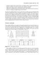
Figure 19.12
(a)
The reduction of the feeder contact area which is possible when
using the FEEDEX HD V-Sleeve with a suitable breaker core. (b) Sectioned spring
loaded steel location pin for ram-up of a V-sleeve without a breaker core.
(b)
φ
84
φ
56
32 × 58
A = 55 cm2 (100%)
A = 25 cm2 (45%) A = 15 cm2 (25%)
Kalminex 2000
ZP 6/9K/11
M = 1, 7
Feedex HD
V 88/10; M = 1, 7
Feedex HD
V 88/40; M = 1, 7
(a)
Feeding of castings
317
850 mm for the modulus range between 2.4 and 22.0 cm and are suitable for
larger sized castings.
The manufacturing process specifically developed for this exothermic-
insulating product and the selection of specific raw materials give a total
closed pore volume of nearly 50%. The excellent heat insulation resulting
(a)
(b)
Figure 19.13
(a) The application of FEEDEX HD V-Sleeves to a ductile iron
turbocharger casting. (b) VS-Spot feeder practice. The point feeding technique makes
possible the production of high value, lightweight castings.
318
Foseco Ferrous Foundryman’s Handbook
from the low density (compared with moulding sand) is enhanced by an
exothermic reaction.
When determining the solidification times with KALMINEX Feeder
Sleeves it has been found that they extend the solidification time by a factor
of 2.0 to 2.4 compared to the natural sand feeders of the same size. From
these results modulus extension factors (MEF) of 1.3 to 1.55 have been
found.
Under practical conditions it has been found that KALMINEX Feeders
when adequately covered with KAPEX lids or a suitable APC (anti-piping
compound) may render up to 64% of their contents into the casting. When
using feeders with the correct modulus it is necessary to take into account
that the modulus of the residual feeder (if more than 33% of the feeder
volume is fed into the casting) may not be adequate in relation to the casting
modulus towards the end of the solidification. Therefore it is essential to
calculate shrinkage as well as modulus when determining the size of the
feeder sleeves.
Foseco provides tables allowing KALMINEX feeders to be selected with
the desired modulus, volume (capacity) and dimensions. Several different
shapes of KALMINEX feeders are available Fig. 19.14a,b,c. Breaker cores
are generally made of chromite sand, though they can be produced in silica
sand.
KALMINEX cylindrical feeder sleeves
KAPEX Lid
φ
0
φ
d
H
Standard Breaker Core
(a)
Feeding of castings
319
Figure 19.14
(a) KALMINEX cylindrical feeder sleeve with breaker core and KAPEX
lid.
(b) KALMINEX TA sleeve.
(c) KALMINEX oval sleeve.
φ
Do
φ
do
KAPEX Lid
H
h
φ
N
φ
Du
(b)
KAPEX Lid
Standard Breaker Core
H
ba
(c)
T
320
Foseco Ferrous Foundryman’s Handbook
KALBORD insulating material
Although in theory there is no upper limit of inside diameter for using
prefabricated feeder lining shapes for inside diameters above about 500 mm,
manufacture, transport and storage become increasingly inconvenient.
For this reason Foseco has developed KALBORD flexible insulating material
in the form of jointed mats. They can be easily wrapped around a feeder
pattern or made up into conventional sleeves as required for the production
of insulating feeders for very large steel, iron and copper based alloy castings
(Fig. 19.15).
Figure 19.15
KALBORD jointed mats.
Width
Thickness
KALBORD mats are available with 30 mm and 60 mm thickness in widths
up to 400 mm and lengths 1020 or 1570 mm. Their excellent flexibility
permits the lining of irregular feeder shapes. The mat is most easily separated
or shortened with a saw blade.
Produced from high heat insulating materials, 30 mm mats achieve a 1.2
fold and 60 mm mats a 1.3 fold extension of the modulus. It is recommended
that KALBORD feeders are covered with FERRUX anti-piping powder.
KALPAD prefabricated boards and shapes
KALPAD has been developed by Foseco to provide a light-weight, highly
refractory insulating material to avoid metal padding and to promote
directional solidification. If KALPAD insulating shapes are used the desired
shape of the casting need not be altered. This increases yield and reduces
fettling and machining costs. For this purpose KALPAD is used in copper-
base metal and steel foundries, in particular, however, in malleable iron and
grey iron mass production.
Owing to a special manufacturing process and the use of alumina mineral
fibres KALPAD shapes have a density of 0.45 g/cm
3
with more than 60% of
the volume being closed pores which are the reason for the high insulation
and refractoriness. During pouring KALPAD produces only negligible fumes
and behaves neutrally towards moulding materials and casting metals.
When evaluating solidification times on KALPAD padded casting sections
it has been found that they extend the solidification time by a factor of 2.25
to 2.5 compared with conventionally moulded castings. From these results
Feeding of castings
321
modulus extension factors of 1.5 to 1.58 have been calculated. It is
recommended to use a factor of 1.5 if KALPAD shapes of 20 to 25 mm
thickness are applied. The dimensions of KALPAD boards and shapes are
shown in Fig. 19.16.
Figure 19.16
KALPAD prefabricated boards and shapes.
300
22
500
KALPAD board 1001
Packing unit: 165 pieces, or as required
550
300
22
50 50
KALPAD jointed mat 1002
Packing unit: 120 pieces, or as required
300
45
140
r
= 420
KALPAD pad 1012
Packing unit: 15 pieces
KALPAD 1001 and 1002 are standard types which can be easily sawn to the desired shapes.
KALPAD 1012 is an example of an insulating pad for runner wheels and gear rims.
Shapes made to measure for mass production upon request.
10 Segments
322
Foseco Ferrous Foundryman’s Handbook
KAPEX prefabricated feeder lids
KAPEX LD insulating feeder lids (Fig. 19.14a) are an improvement over the
hot-topping powders in foundry use, being dust and fume free and giving
repeatable feeding results. They can be applied to all feeders either exothermic,
insulating or natural. The lids have an insulator density of 0.45 g/cm
3
and
are purely insulating. Owing to their neutral behaviour towards moulding
material and casting metal they are used in light metal and copper-base
foundries as well as in high alloy steel foundries. KAPEX LD lids have
replaced over 50% of the hot-topping used in Europe for sleeves of diameter
between 100 and 350 mm and their use is still growing.
For smaller neckdown feeder sleeves, KALMINEX 2000 exothermic KAPEX
lids are also available.
KALPUR filter feeder units
KALPUR filter feeder technology is the shortest way to a perfect casting,
see pp. 266, 289. There are two types of KALPUR filter feeder products; one
for mass production foundries and the other for jobbing foundries. For
mass production, KALPUR insert filter feeder units are inserted and secured
into the mould cavity, created by means of suitable KALPUR insert patterns.
KALPUR KSET filter feeder units with upper filter location are supplied for
horizontally parted automatic moulding machines, Fig. 19.17. For vertically
parted moulding lines, KALPUR units with lower filter position are used
Fig. 19.18.
For jobbing and simple moulding machine application KALPUR ram-up
filter feeders, Fig. 19.19a are used by means of a centering support pattern
in combination with a protective bridge pattern Fig. 19.19b.
KALMINEX 2000 ZTAE KALPUR exothermic units and insulating
KALMIN STP units are available for ram-up applications.
Use of the KALPUR unit eliminates the conventional gating system and
creates the ideal directional solidification condition. The KALPUR filter
feeder units must be selected according to their modulus and flow rate with
a filter type appropriate to the alloy being cast.
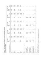
Table 19.5 The KALPUR filter feeder product range
Name Material Alloy AppIication* Diameter range (mm)
KALMIN S KSET Insulating NF; iron, steel Horizontal insert 50, 60, 70, 80, 90, 100
KALMIN S KSE Insulating NP; iron, steel Vertical insert 60 and 90
KALMIN 70 STP Insulating NF; iron, steel Jobbing ram-up 50, 70, 90, 125
KALMINEX 2000 Exothermic- Iron and steel Jobbing ram-up 100, 120, 150, 180
ZTAE insulating
*NB for aluminium, iron and steel casting KALPUR types are KALPUR AL; KALPUR FE and KALPUR ST
respectively in which SIVEX; SEDEX/CELTEX and STELEX filters are integrated.
Feeding of castings
323
Breaker cores
Breaker cores for the reduction of the feeder-to-casting contact area enable
feeders to be broken off or knocked off from many types of castings. In the
case of very tough casting alloys where it is not possible to simply break off
or knock off the feeder, the advantage of using breaker cores lies in the
reduction of fettling and grinding costs for the removal of the feeder.
KALPUR Fe
KSET 8/11/L10
23
30
10
20
40
25
20
40
20
40
(a)
(b)
Figure 19.17
(a) KALPUR insert filter feeder units with upper filter location for
horizontally parted automatic moulding lines. Without breaker core for direct pouring
through a side feeder. With breaker core for direct pouring through a top feeder.
(
b) KALPUR Fe Insert side feeder used for feeding two ductile iron case covers.
324
Foseco Ferrous Foundryman’s Handbook
(a)
Figure 19.18
(a) KALPUR pouring cup filter-feeder units with lower filter position
for vertically parted moulding lines. (b) KALPUR pouring technique used on a
DISAMATIC moulding line for casting ductile iron hydraulic arms.
(b)
Figure 19.19
(a) KALPUR ram-up filter feeder series for jobbing and simple moulding
machine applications. (b) Ram-up principle with fixed centering support and a loose
‘bridging’ pattern to give the correct height.
(a)
(b)
Bridging pattern
Centering support
Feeding of castings
325
Besides the conventional types of breaker cores based on silica sand
(Croning) and chromite sand, special breaker cores with a very small aperture
are also in use in repetition iron foundries. These special breaker cores as
shown in Table 19.5 are made from highly refractory ceramic.
Table 19.5 Application of breaker cores
Breaker core material Casting metal Feeder diameter (mm)
Silica sand Steel 35–120
Silica sand Grey, ductile iron, 35–300
non-ferrous metals
Ceramic Grey, ductile iron, 40–120
non-ferrous metals
Chromite sand Steel 80–500
Chromite sand Grey, ductile iron 200–500
Experience has shown that at least 70% of the breaker core area should be
in contact with the casting, in order to level out the temperatures of the
metal and the breaker core from the superheat upon or before reaching
liquidus.
Some of the standard forms of breaker core available from Foseco are
shown in Fig. 19.20. Foseco feeder sleeves can be ordered with or without
breaker cores attached.
Figure 19.20
Standard forms of breaker cores.
Standard Breaker core
(…/11)
Standard Breaker core
(…/14)
Ceramic Breaker core
(…/11 K)
Standard Neck-down Breaker core
(…/31)
The application of feeder sleeves
Ram-up jobbing applications
(1) Manual moulding
Sleeves of the correct dimensions are set on the individual pattern in the
predetermined location and the mould is rammed around the sleeves. The
base of the sleeve should not come into direct contact with the casting but
be set on a sand step at least 10 mm thick or the sleeve should be fitted with
a breaker core.
326
Foseco Ferrous Foundryman’s Handbook
(2) On semi-automatic, cold set and slinger moulding lines
If the pattern plate is accessible to the machine operator, the feeder sleeve is
located by hand on the pattern plate. To avoid damage during machine
moulding, sleeves should be supported by standing them on a pattern dummy
or peg at the correct location and having the correct shape and height.
Figure 19.9 shows one such arrangement.
Insert sleeves
Often on high pressure, squeeze press or air impact moulding lines, pattern
plates are no longer accessible. Foseco recognised these changes in the late
1970s and early 1980s and developed insert sleeve application systems
allowing fully automatic machine users to retain all the advantages of
employing feeder sleeves without slowing down the moulding cycle.
A prefabricated feeder sleeve with strictly controlled dimensional tolerances
is inserted into a cavity formed during the moulding operation by a sleeve
pattern of precise dimensions located on the pattern plate (Figs 19.10,
19.11).
The insert sleeve patterns are fixed by screwing them onto the casting
pattern and they provide the cavity for the insert sleeve. Owing to the
special sealing and wedging system no metal can penetrate behind the
inserted sleeves and these cannot fall out from their seat during closing and
handling of the mould.
The design of the insert patterns also forms highly insulating air chambers
behind the inserted sleeves. This additional insulation increases the moduli
of the insert sleeve feeders as follows:
FEEDEX Insert Sleeves HDP + 5 %
KALMINEX 2000 Insert Sleeves ZP + 5 %
KALMIN S Insert Sleeves KSP + 4 %
The insert sleeve patterns have a solid aluminium core with mounting thread
and a highly wear resistant resin profile. Insert sleeve patterns are available
corresponding to the various types of insert sleeves with and without breaker
cores. Both insert sleeves and insert patterns are thus part of an integral
system.
Floating feeder sleeves
This is a relatively simple application technique with low feeder sleeve
application cost since feeder sleeves are simply placed on the drag parting
line. The method is applicable for all moulding machines having a horizontal
mould parting line. No problems are encountered regarding strength, spring
back etc. of the feeder sleeve. On high pressure moulding lines, more economic
and non-polluting insulating KALMIN sleeves can be applied.
Feeding of castings
327
A two-part sleeve pattern is used with an integrated feeder base and
feeder neck (Fig. 19.21). The drag sleeve pattern is secured on to the drag
pattern plate which creates a suitable location and positioning cavity for the
corresponding feeder sleeve. The feeder sleeve is simply positioned on this
location cavity (Fig. 19.22a). The cavity created by means of the cope sleeve
pattern ensures location of the feeder sleeve while closing the mould. After
pouring, the feeder sleeve floats along with the liquid metal, secures and
seals itself tight into the mould wall cavity created by means of the cope
sleeve pattern (Fig. 19.22b).
φ
Do
H
Cope pattern
φ
DU
Drag pattern
2°
M
2°
B
DU2
DU1
L
Bottom view
M
Figure 19.21
Sleeve pattern for a floating sleeve. The cavity created by means of
the cope sleeve pattern ensures location of the feeder sleeve while closing the
mould.
The floating sleeve patterns incorporate maximum feeder neck dimensions
applicable to iron castings. For steel, light alloys and non-ferrous alloys,
neck modulus can be modified to usual casting modulus equal to neck
modulus. For full details, refer to Foseco leaflets.
A
328
Foseco Ferrous Foundryman’s Handbook
Shell mould application
Sleeves may also be inserted into shell moulds. The principle is the same as
for green sand moulding, special sleeve patterns are available which form
ridges in the sleeve cavity which grip the inserted sleeve but do not damage
the mould (Figs 19.23 and 19.24).
Vertical mould or DISA application
Insert sleeves can be applied equally to moulds with a vertical parting, such
as those made on the Disamatic moulding machine. The sleeve pattern is
divided, but off centre, one part being slightly smaller than the other. The
two parts are mounted on opposite sides of the Disamatic pattern plates
with the sleeve located in the larger cavity and held in place by the exact
vertical fit of the sleeve in the mould. When the mould is closed the second
half holds the sleeve fully in position.
Core application
Feeder sleeves may also be inserted into cores. For example, ductile iron
hubs are often fed by one or more side feeders located externally to the
flange but the most efficient feeding method is by means of a sleeve located
in the central core and connected to the casting at the point where the feed
metal is really needed. The sleeve is placed into the core print location and
fits into the cope mould cavity created by the appropriate sleeve pattern
(similar to a floating sleeve pattern); the result is an improvement in yield,
cleaning costs and casting soundness (Fig. 19.25).
feeder sleeve
cope
ingate
drag
feeder base
neck
casting
Figure 19.22
Floating sleeve functional principle. After pouring, the feeder sleeve
floats along with the liquid metal and seals itself tight into the mould wall cavity
.
(a) (b)
Feeding of castings
329
Williams cores
The purpose of a Williams core is to prevent the top of the sand feeder
solidifying prematurely so that atmospheric puncture can take place on top
of the feed metal to promote adequate feeding of the casting. Williams cores
are supplied in a range of sizes up to 66 mm diameter D, Fig. 19.26, in
FEEDEX exothermic material. KALMIN S and KALMINEX 2000 parallel
conical insert sleeves are manufactured with a Williams Wedge incorporated
into the design (Fig. 19.8).
D0
D01
x top
R8
R1
M10
H1
H
60
x bottom
DU
DU1
H2
90°
120°
y bottom
y
top
Figure 19.23
Sleeve pattern for shell mould application.
330
Foseco Ferrous Foundryman’s Handbook
Figure 19.24
A shell mould with feeder sleeves (sectioned for clarity) located in
the cavity formed by the shell mould sleeve pattern.
Figure 19.25
A ductile iron hub casting using a sleeve located in the central core.
The sleeve is placed into the core print location and fits into the cope mould cavity
created by the appropriate sleeve pattern.
Feeding of castings
331
FERRUX anti-piping compounds for iron and
steel castings
The FERRUX range includes anti-piping compounds of all types with reactions
in contact with the molten metal which vary from very sensitive, highly
exothermic to purely insulating. Described as examples are three grades of
FERRUX manufactured in the UK which cover the requirements of the
complete range of all ferrous alloys cast in all feeder diameter sizes.
All three grades have an exothermic reaction and one of them, FERRUX
707F, by expanding in use, incorporates the most modern technology. The
examples detailed below therefore should only be considered as typical of
the types of FERRUX grades and the technology which is available.
The anti-piping compound, pre-weighed and bagged, should be added
in the bag to the surface of the metal immediately after pouring has been
completed. It is advisable to design the feeder to pour slightly short so that
a space can be left between the surface of the metal and the top of the
mould. FERRUX will then be contained in this space. The recommended
application rate is a layer which has a thickness equivalent to one tenth of
the diameter or 25 mm whichever is the greater. If after application the
powder is not evenly distributed then the upper surface should be raked
flat; normally this will not be found to be necessary.
Note that, for environmental and practical reasons, KAPEX insulating
lids are replacing hot-topping compounds in many applications, see p. 322.
FERRUX 16
This is a carbon-free, sensitive, fast reacting exothermic anti-piping compound
of high heat output. After the exothermic reaction has ceased, a firm crust
Figure 19.26
Williams cores.
φ
D
φ
D
′
φ
d
φ
d
φ
D
φ
d
′
H
H
′
Shape I (without flange) Shape II (with flange)
332
Foseco Ferrous Foundryman’s Handbook
remains on top of the feeder. It is particularly recommended for use on
feeders where rapid sculling takes place and where carbon contamination is
to be avoided. Feeders where FERRUX 16 is most often employed are in the
diameter range 25–200 mm.
FERRUX 101
This is an exothermic anti-piping compound of medium sensitivity. It is
ideal for general steel foundry use on feeders of 150 mm diameter and
upwards. It may also be used on iron casting feeders where the crust formed
after the exothermic reaction has ceased, forms a good insulation against
heat losses. The crust can be broken for topping up large castings. The
absence of carbonaceous materials in the product ensures that no carbon
contamination of the feed metal will occur.
FERRUX 707F
This is a medium sensitivity, exothermic anti-piping compound which expands
during its reaction to approximately twice its original volume, to produce a
residue of outstanding thermal insulation. In spite of the exothermic reaction,
FERRUX 707F is virtually fume free and, in addition, because of the expansion
and because of the product’s lower density, the original weight of FERRUX
707F which has to be used for effective thermal insulation is usually only
about half that of non-expanding grades. The low carbon content of this
product will not normally affect metal quality in any significant way. FERRUX
707F is most generally employed for steel and iron feeders of 150 mm diameter
and upwards.
Metal-producing top surface covers
THERMEXO is a powdered, exothermic feeding product which reacts on
contact with the feeder metal to produce liquid iron at a temperature of
about 2000°C. The product is designed for emergencies in case of metal
shortage.
Even in the best foundries, occasionally the weight of metal left in the
ladle is overestimated and a casting is poured short. The addition of a metal
producing compound may save the casting by providing the extra feed
metal necessary. In such cases the foundry has nothing to lose by trying a
metal producing compound and it is for emergency reasons that every steel
foundry should have a stock of THERMEXO.
FEEDOL anti-piping compounds for all non-ferrous alloys
The lower casting temperatures and the differing chemical requirements for
non-ferrous alloys necessitates a completely different range of anti-piping
compounds than that used on ferrous castings. FEEDOL is the name given
Feeding of castings
333
to Foseco’s range of anti-piping compounds for non-ferrous castings. As an
example, two of the principal FEEDOL grades manufactured in the UK are
described in detail below.
FEEDOL 1
This is a mildly exothermic mixture suitable for all grades of copper and
copper alloys. The formulation does not contain aluminium and there is
therefore no risk of contamination where aluminium is an undesirable
impurity. After the exothermic reaction has ceased, FEEDOL 1 leaves a
powdery residue through which further feeder metal can be poured if
necessary. FEEDOL 1 is useful for feeders up to 200 mm diameter. For very
large copper based alloy castings such as for example, marine propellers,
FERRUX 707F is to be recommended.
FEEDOL 9
This is a very sensitive and strongly exothermic compound recommended
for use with aluminium alloys. After the completion of the exothermic
reactions the residue forms a rigid insulating crust. FEEDOL 9 is recommended
for aluminium alloy feeders of all sizes.
The development of Foseco feeding technology
Fifty years ago, foundries made their own feeder sleeves from sacks of
FEEDEX powder supplied by Foseco. In the 1960s Foseco developed a vacuum
production technique for the large-scale manufacture of insulating KALMIN
and exothermic-insulating KALMINEX sleeves in standardised cylindrical
and oval types. At the end of the 1960s the highly exothermic-insulating
KALMINEX S sleeve was developed for application on high production
moulding machines, placed on the pattern plate and rammed up to form a
side feeder. With the increased use in the 1970s of ductile iron for high
volume castings and the use of automatic moulding machines which did
not allow access to the pattern plate during the moulding cycle, Foseco
developed the insert sleeve concept which is still widely used in many high
production iron foundries. This concept also made possible the broader
application of breaker cores. At the end of the 1990s, more than 60% of all
insert sleeves supplied by Foseco have breaker cores.
In the 1990s the V-sleeve concept of a small feeder volume and a small
feeder application area allowing ‘spot’ feeding of castings was developed.
By the mid-1990s V-sleeve technology was introduced into most mass
production iron foundries. At the end of the 1990s many foundries combine
the insert and V-sleeve technologies on fast moulding machines. This allows
castings requiring a large number of feeders to be made within the short
moulding cycle time available.
The latest VS-Spot feeder is connected to the casting by a very small
feeder neck which can be removed with a hammer blow leaving only a
small stub to be ground off.
334
Foseco Ferrous Foundryman’s Handbook
The KALPUR filter feeder unit allows conventional gating systems to be
eliminated and creates ideal directional solidification of the casting.
Figure 19.27 illustrates the range of Foseco feeder and filter-feeder products
presently available.
Figure 19.27
Some of the available Foseco feeding and filter-feeding units. (This
figure is reproduced in colour plate section.)
Aids to the calculation of feeder requirements
Tables
Tables have been drawn up which will convert natural feeders to sleeved
feeders for steel castings. No knowledge of methoding is required all that is
necessary to know are answers to the following questions.
(a) What are the dimensions of the natural feeder?
(b) What is the weight of the casting section being fed?
(c) What is the alloy composition?
(d) Is the casting with the natural feeder sound?
The tables will do the rest. The conversion, however, is very primitive for if
the natural feeder is too large then the sleeved feeder will also be too large
and conversely if the natural feeder is too small and causes shrinkage so
will the sleeved feeder.
KALMINEX cylindrical and oval feedersleeves
KALPUR
Ram up filter-feeder
KALPUR
Insert filter-feeder
KALMINEX
Insert sleeve
FEEDEX HD
V-Feeder, VS-Feeder, VS-Spot feeder
Feeding of castings
335
Similarly a simple table has been compiled for ductile iron castings. It is
simple to use and requires no expert knowledge of methoding practice.
Although in most cases the recommendation if followed will give a suitable
feeder sleeve it is not necessarily the optimum size for a given casting
section. The table compiled by Foseco in the UK is shown as Table 19.6.
Table 19.6 Feeding guide for ductile iron castings
Weight of casting Sleeve type Sleeve unit No. Feed metal wt.
section (kg) KSP, ZP, HDP insert tapered in sleeve (kg)
270.0 16/15 KC3830 19.5
180.0 14/15 KC3826 13.9
130.0 12/15 KC3324 9.8
82.0 10/13 KC3168 5.7
60.0 9/12 KC3596 4.8
37.0 8/11 KC3164 3.0
26.0 7/10 KC3160 2.2
14.0 6/9 KC3156 1.4
8.9 5/8 KC3152 0.92
6.8 4/95 KC3148 0.77
4.5 4/7 KC3144 0.55
1.7 3.5/5 KC3998 0.23
Nomograms
A series of nomograms which relate the casting modulus, which has to be
calculated, and the weight of the casting section to a suitable size of feeder
sleeve has been developed. Two examples are shown in Fig. 19.28. Such
nomograms have distinct disadvantages, they do not take into account many
of the variables commonly found in steel foundries, they are however a
significant step forward for feeder recommendations can be made without
the need to know the original natural feeder dimensions.
FEEDERCALC
FEEDERCALC is a Foseco copyrighted PC computer program which enables
the foundry engineer to make rapid, accurate calculations of casting weights,
feeder sizes, feeder neck dimensions and feeding distances and to make
cost analyses to quickly determine the most cost-effective feeding system
for any given casting. Versions of FEEDERCALC have been produced for
iron and for steel castings.
The program has been designed by foundrymen for foundrymen and
requires only a basic understanding of Windows. Note that the FEEDERCALC
program does not replace the experienced methods engineer for it relies on
the engineer’s skill to interpret drawings, determine feeder locations and
accommodate the particular production practice of the engineer’s foundry.
The program includes:
336
Foseco Ferrous Foundryman’s Handbook
Weight estimation: Combinations of geometric shapes can be easily
manipulated to estimate the weight of complex castings or casting sections.
Feeding distance: Feeding distances can be calculated, with and without
the use of chills. This allows the rapid determination of the number of
feeders required for the casting or casting section.
Feeder size calculation: Accurately calculates the optimum feeder size from
a selection based on the complete range of Foseco feeding products. A
selection can then be made to meet individual production requirements.
Side-neck calculation: Facilitates the calculation of neck dimensions, weight
and fettling areas from the minimum neck modulus supplied in the feeder
size calculation.
Cost analysis: Enables the foundry engineer to select not only the optimum
but also the most cost effective technique for each casting. Cost data
defaults can be used or values specific to the foundry can be entered by
the operator.
Casting information: Information relevant to each casting analysed using
FEEDERCALC can be saved along with the above data, namely Methods
Engineer, Pattern No., Drawing Number etc. Therefore, all records
applicable to the casting can be stored and retrieved using FEEDERCALC.
FEEDERCALC for Windows
(Versions 1.0 or later) requires the following computer hardware to run
effectively.
100% IBM compatible computer (386 processor minimum; 486 or Pentium
recommended)
Feeding guide for steel castings
using KALMINEX 2000S
Feeding guide for steel castings
using KALMINEX 30 sleeves
Weight of casting section (kg)
200
150
100
50
40
30
20
10
5
2
16/15
14/15
12/15
10/13
9/12
8/11
7/10
6/9
5/8
4/7
3.5/5
Blind
Open
16/15
14/15
12/15
10/13
9/12
8/11
7/10
6/9
5/8
4
3.5
3
2.5
2
1.5
1
0.5
Casting modulus (cm)
Weight of casting section (kg)
10 000
9000
8000
7000
6000
5000
4000
3000
2000
1500
1000
900
700
500
400
300
200
100
50
Height (in)
30
24
18
12
20
18
16
14
6
12
8
10
6
30
18
24
12
6
Diameter (in)
20
18
16
14
12
10
8
6
12
11
10
9
8
7
6
5
4
3
2
Modulus (cm)
Figure 19.28 Examples of nomograms used to determine suitable feeder sleeve
dimensions.
Feeding of castings
337
Minimum 4 MB memory
Hard Disk (minimum 2MB available space)
3
1
/
2
" disk drive
Windows version 3.1 or later
Microsoft Mouse
VGA (or higher) graphics capability
Any printer configured for use with Windows (if hard copy is desired).
The opening Information Screen, (Fig. 19.29) allows the user to save details
of a specific casting method and to select the units and material density to
be used for the calculation. The default language to be used can also be
chosen from English, French, German, Portuguese, Spanish or Italian.
Figure 19.29
FEEDERCALC Information screen.
Weight calculation
Single clicking on this tab displays the Weight Calculation screen shown in
Fig. 19.30. This screen is used to estimate the weight of a casting or casting
section. Weights of complex castings or casting sections are calculated by
breaking the casting down into simple shapes, entering dimensions to calculate
the weight of each shape, and combining all of the weights to give a total
weight for the casting or casting section. (Shape weights may be added to,
or subtracted from, the total.)
338
Foseco Ferrous Foundryman’s Handbook
Feeding distance
Once the weight of the casting has been estimated, the Feeding Distance
section of the program is used to determine how many feeders are required
to feed the casting (see Fig. 19.31).
In the Iron version, the Feeding Distance program is based on a combination
of the work of Holzmuller and Wlodawer (whose work relates feeding
distance to the amount of graphite present in the alloy), and of the work of
R. Heine and of Wallace, Turnball and Merchant relating feeding distance in
ductile and grey iron castings to both mould hardness and casting section
(modulus). In addition, the calculations in FEEDERCALC have been
augmented with empirical casting data based on practical experience. If
lower soundness standards are acceptable for the particular casting in
question, the user may extend feeding distances shown by the program,
based on specific alloy or mould material being used and the user’s experience.
The program assumes vertical feeding distance to be equal to horizontal
feeding distance. Shrinkage or expansion of the alloy under consideration is
calculated by inputting total Carbon, Si and P. From this data the program
calculates the shrinkage value for the alloy. The mould material pull down
list allows the nearest type of mould material to be selected. This is important
in ductile irons because mould wall movement must be taken into account.
In the Steel version, the Feeding Distance program is based on horizontal
feeding distance path data published by the Steel Founders Society of America
and is recommended for low carbon steel sections down to 25 mm thick (to
A1 radiographic standard) cast in green sand. If lower soundness standards
Figure 19.30
FEEDERCALC weight calculation screen.
Feeding of castings
339
are acceptable for the casting in question, the user may extend feeding
distances shown by the program, based on the specific alloy or mould material
being used and the user’s experience. The program assumes vertical feeding
distance to be equal to horizontal feeding distance. The user can now design
feeders for the casting by accessing the Feeder Design section of the program.
The mould material is selected from a pull down list and the shrinkage of
the alloy being used calculated from the type of steel used and the pouring
temperature.
Feeder size calculation (Fig. 19.32)
The program determines the optimum size of sleeve required in each Foseco
product line which will meet the requirements for the casting section being
considered. It also calculates the smallest possible sand feeder which will
meet these same conditions, enabling a comparison to be made.
The calculation is based on:
Feeder position
Casting section weight
The section DIS (Diameter of Inscribed Sphere) in the casting section
adjacent to the feeder in question
The number of non-cooling faces
The ingate position and type
Figure 19.31
FEEDERCALC feeding distance screen.