Coatings of Polymers and Plastics part 15 doc
Bạn đang xem bản rút gọn của tài liệu. Xem và tải ngay bản đầy đủ của tài liệu tại đây (470.06 KB, 21 trang )
Automotive Plastic Coatings in Europe 339
T
ABLE
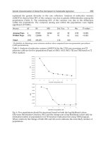
8 Application Parameters for Waterbased Basecoats
First spraying operation Metallic basecoats approximately 6–8 µm dry film
thickness
Air speed 0.4 to 0.6 m/s
Relative air humidity 60 +/− 5%
Room temperature 23 +/− 3°C
Intermediate flash-off Approximately 2 min. @ 23 +/− 3°C
Second spraying operation Metallic approximately 6–8 µm dry film thickness
Air speed 0.5 m/s +/− 0.1 m/s
Relative air humidity 60 +/− 5%
Room temperature 23 +/− 3°C
Air lock (Approximately 3 to 5 min.)
Final flash-off Approximately 6 min. at 60°C (drier rated for 80°C)
on work piece 2 +/− 0.5 m/s
Cooling The substrate in the discharge lock of the blowing
tunnel with fresh air to 30°C
for the processing of waterborne paints. A case-to-case examination has to be
made as to whether integration into existing painting lines is possible. However,
the paint supply system and the application technology must always be adapted.
The most widely used pneumatic application process, manual and/or auto-
matic processing, is described in detail as an example. In general, the parameters
also apply to electrostatic processing. Further details are given in the next para-
graph.
The effect of the humidity (see processing range) is more crucial with
waterborne basecoats than with conventional systems. Even after a 10-minute
flash-off period there is still too much residual solvent in the paint film under
T
ABLE
9 Pneumatic Spray Application Parameters
Hand spray gun, stainless steel DeVilbiss JGV-563 St
Automatic Gun, alternatively DeVilbiss AGMD, ABB, Behr
Nozzle (∅ mm) 1.1/1.4
Air cap (DeVilbiss) 765/789/797
Sprayer air pressure (bar) dynamic 4–5 5–6
Material flow rate (ml/min.) 200–400 200–400
Object distance (mm) 250–300 250–300
Booth temperature (°C) 23 +/− 323+/− 3
Relative air humidity (%) 60 +/− 560+/− 5
(best spraying
conditions)
Down draft (m/s) 0.5 +/− 0.1 0.5 +/− 0.1
340 Gruner and Reinhart
normal booth conditions and therefore a special evaporation tunnel is needed.
In the actual painting of plastics a combination of infrared drying and subse-
quent blowing off with heated air has not proved successful for the forced evap-
oration of waterborne basecoats and instead pure convection drying is recom-
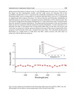
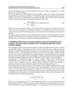
mendable. Figure 9 shows a temperature curve for this basecoat clearcoat
application and bake process.
Over the last years, several new concepts for the integration of waterborne
basecoats into existing paint shops have been introduced. Due to the three-
dimensional, complicated geometry and poor temperature stability of many plas-
tic parts, development of high-temperature radiation dryers (like infrared [IR]
and ultraviolet [UV]) could not be introduced. With the exception of some mid-
dle- or long-wave infrared heaters, and also a few catalytic gas dryers (for
smaller and more flat parts) in Great Britain and in France, process engineers
and plastic coaters studied alternate dryers that operated at low temperature and
worked on the principle of condensation. For these types of systems, closed air
circulation is needed and the relative humidity must be less than five grams
per kilogram of air. Processing temperatures are approximately 40°C. These
conditions offer the benefit of a shorter process and the typical cooling time
period that is required after drying is not necessary.
F
IG
.9 Temperature curve for waterbased basecoat–waterbased clearcoat.
Automotive Plastic Coatings in Europe 341
In view of the increasing significance of painting plastic surfaces electro-
statically, this process is explained in more detail. Electrostatic painting has
been the main standard method for coating metallic substrates for many decades.
The advantage of this technique is the low loss of paint mist compared with
purely pneumatic spraying processes. As a result, it is a cost-effective method
of delivering paint to a part.
Particularly more and more color harmony is required between the car
body and the plastic parts. This can be very challenging because most off-line
application methods are not at all similar to that of the car-body paint lines. In
an attempt to improve this color harmony, conveyor systems have been built to
hang and carry the plastic parts in car-body position through the plastic paint
line. Also the application concept with the typical electrostatic atomizer is in
use, similar to that used with the car body. Examples of robot types used in
Europe are ABB and Fanuc.
Electrostatic units operate on two principles, the purely electrostatic
method and those methods with additional auxiliary energy for paint atomiza-
tion. One thing that all processes have in common, however, is the fact that
electrostatically charged paint droplets when sprayed are transported to the
grounded part under the action of the electrostatic field and deposited on the
job. Electrostatic application on plastics is a little more sensitive than the pro-
cess used on the car body, as the typical plastic part is not inherently conductive.
For optimum transfer efficiency the experience is, that a specific system resis-
tance has to be less than one Mega-Ohm. Best results are measured in a combi-
nation of waterborne basecoat with an underlying layer of conductive primer.
The high conductivity of the wet waterborne paint increases the transfer effi-
ciency higher than normal.
Electrostatic painting using high-rotation atomization is characterized by
a considerably higher transfer efficiency (24,25) compared with pneumatic at-
omization. Spraying is performed purely mechanically at the bell edge. This
process promises to exhibit the highest efficiency for coating plastic parts. Un-
der the pilot plant conditions at DuPont, paint utilization of up to 60 percent
was attained on bumpers whereas in a conventional pneumatic plant approxi-
mately only 30 percent is achieved. In practice, these figures are considerably
lower when applied through electrostatic application owing to poor grounding.
In spite of these advantages, the use of electrostatic high-rotation sprayers has
for a while only been partially implemented for the application of “effect” base-
coats. Normally, variations in color and a different flop behavior compared with
pneumatic atomization occurs, which would clearly become noticeable as an
optical flaw in the repair of parts without electrostatics in series production or
in the field.
The color and effect deviations that are usually seen are attributed to the
different atomization and transport conditions of the paint droplets, the different
342 Gruner and Reinhart
evaporation behavior of the solvents contained in the atomized droplets and the
different kinetics of the droplets when they impact on the surface being painted.
These differences induce an alignment of the aluminum platelets or other effect
pigments causing the color deviation (see Fig. 10). However, in spite of this
limitation, currently between 50 and 70 percent of the dry film thickness of
effect basecoats can be applied electrostatically without any loss of optical qual-
ity. To apply as much as possible, ideally up to 100 percent of the basecoat,
through electrostatical application requires close cooperation of all partners
throughout the whole development process, starting with the OEM stylists.
Surface tension, viscosity, and the paint thickness influence the droplet
size distribution and the average droplet diameter just as much as the angular
velocity, diameter, and specific design details of the sprayer in conjunction with
the paint throughput. In this context, the very low electrical resistance of the
water in water-thinnable basecoats deserves special attention. If the paint is
supplied from a closed-circuit pipe, the high voltage present at the spraying
head owing to the paint column created can be discharged into the entire supply
system. The possibility of completely interrupting the paint column with opti-
mum safety by means of intermediate replenishing tanks operated in isolation
was previously used with waterborne fillers in automobile painting. Figure 11
shows a typical replenishing tank system. As a replenishing tank located in the
voltage cascade and requiring a relatively large space was needed for each color,
F
IG
.10 Aluminum- or mica-flake orientation in HR-bell and pneumatic spray.
Automotive Plastic Coatings in Europe 343
F
IG
.11 Intermediate replenishing tank system, ohmic insulated for electrostatic
waterbased basecoat application. (Courtesy of: LACTEC GmbH, Rodgau, Germany.)
344 Gruner and Reinhart
it was not possible to transfer such a solution to basecoats with their wide
variety of shades.
At present, the standard solution for basecoats is therefore still the concept
of high-rotation atomization with external charging. In this case, the paint is
merely sprayed by high rotation. The electrostatic charge is created in a second
stage by the air ions attaching themselves to the paint droplets in the high-
voltage field between the external charging electrodes and the object being
painted. The field geometry, voltage, shaping air, air velocity, and air humidity
in the booth must be set in relation to each other so that return-spray effects,
which could lead to contamination of the electrodes, are avoided.
7.3 Clearcoats
Due to the plastics and molding conditions used by the European automotive
industry, the maximum curing condition for bumpers, grilles, side claddings
and most other plastic items is 90°C (194°F). Therefore, since the early 1980s
isocyanate curing 2K clearcoats have been used. Initially, highly flexible, poly-
ester resins were needed in the backbone to avoid deterioration of the low-
temperature impact resistance of the painted part. A cryogenic polishing tech-
nique, using liquid nitrogen, was carried out to touch up any of these parts when
and if defects were seen. More recently, clearcoats have been developed with
built-in flexibility providing good low-temperature impact, which can be pol-
ished at ambient temperature.
In terms of resin chemistry, the clearcoats are based on a hydroxy-func-
tional polyester and acrylic-resin blend. The polyester is responsible for provid-
ing the high flexibility at low temperature. The hardener is based on hexamethy-
lene diisocyanate (HDI) trimer. Ultraviolet absorbers (UVA), and hindered
amine light stabilizers (HALS) are additives added to absorb UV light, protect
the basecoat pigments and to quench free radicals that could deteriorate and
decompose the backbone resins.
To meet the need for very robust products, new products are continually
being developed that may be applied at low cost through high pressure spray
guns or through high-efficiency bells with little risk of popping, nonuniform
film build, or even sagging over a wide range of film builds. High skills are
needed in the formulation chemist. Formulation tools are needed to build struc-
tural viscosity to avoid sagging “in the booth,” thixotropy is needed to avoid
sagging in the “flash off” zone, and temperature-induced viscosity is needed to
control the film in the oven on vertical areas of the molded part.
The typical product used on the European continent is a medium solids
2K clearcoat. In the United Kingdom however, local authorities require products
with VOCs less than 420g/l. Clearly, these higher solid products have limited
use compared to their medium solid counterparts when highly effective applica-
Automotive Plastic Coatings in Europe 345
tion with smooth orange peel, even at low film build, is needed. In addition to
solvent-based clearcoats, water-based clearcoats have also been developed and
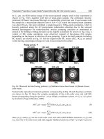
these trial products are under evaluation for industrial use (26). Figure 12 shows
a typical application of a waterbased clearcoat.
8 BODY PARTS
To a growing extent, the European automotive industry uses plastic and thermo-
setting materials for body applications. Two materials, SMC and PPO/PA are
dominating in this area. It was in the early 1980s that SMC first appeared on
middle volume vehicles and since then it has been used to a higher or lower
extent, depending on the automotive OEM. Typical application for these materi-
als are tailgates, an early example being the Audi Avant. Today, SMC plays an
increasing role in this area and a number of variations of this technology are
currently used.
A SMC trunk lid is assembled on DaimlerChrysler’s S-Klasse Coupe. This
part is precoated with an in-mold coating (IMC) and a black conductive primer.
It is assembled to the body and passed through a cathodic electrodeposition
tank, with no coating adhering to the SMC part. The black conductive primer
allows for electrostatic application of primer surfacer and topcoat along with the
automobile body. Renault (VelSatis) and Volvo (V70 station wagon) tailgates
are coated completely off-line, without the use of IMC, and are coated with a
dual primer system consisting of highly conductive primer and a light gray,
F
IG
.12 Application of waterbased clearcoat. A few minutes after application, the
wet film changes from “milky” to “transparent”.
346 Gruner and Reinhart
nonconductive primer on top. Renault also topcoats SMC fenders that are
primed with a conductive powder coating.
Despite many improvements in SMC technology, the major problem of
popping has not been completely eliminated. Porosity, due to gas inclusions
mainly on the edges and wherever the part has been stressed, limits the scope
of many SMC applications. To cope with this inherent porosity best, two “theo-
ries” are followed. The first is to have a process starting with high temperatures
of the primer bake. In this early stage, any pores popping out can be filled with
putty. Due to the lower temperatures used later in topcoat bake, a minimum of
pores are assumed to pop due to a sealing effect of the paint film. The primers
used in this method are 140°C melamine-cured systems. More recently, accord-
ing to the second theory, the overall process to coat SMC should be performed
at low temperature. Low-bake 2K primers have been commercialized to effec-
tively reduce the amount of visible porosity.
In increasing volume, hard polyurethane (PU) composites are commonly
used for body applications, like hardtops. Typically, a reinforced molding cov-
ered by a 3 mm skin, is coated off-line. In addition to thermosetting materials,
highly temperature-resistant thermoplastic polymers have been introduced to
this body technology. A particularly suitable thermoplastic material for body
components is the blend of PPO/PA. The structure is a matrix with spherical
domains due to the noncompatibility of the polymers. As the PA phase is semi-
crystalline, shrinkage phenomena of the plastic also have to be considered.
When using the part for “on-line coating” processes, a topcoat cure of 140°C
(285°C) or higher has to be taken into account with mold dimensions. Typically
in these cases, the provider of the primed part is requested to use 140°C primer
bake to preshrink the part for optimal body fit when assembled to the vehicle.
A few examples illustrate as with SMC parts, for PPO/PA body compo-
nents, many different coating options are used and no general coating process
has been established. DaimlerChrysler’s A-Classe has a Noryl tailgate that is
completely coated off-line in body color. The fenders of the same car however,
are primed using a conductive primer and are assembled “after e-coat” for on-
line coating. This is accomplished using a functional-surfacer, water-based base-
coat and powder slurry clearcoat. Other fenders like that on the Audi A2, are
coated completely off-line. For Renault’s Scenic and Clio models, black conduc-
tive PPO/PA is used so that the part can be coated on-line after passing through
the electrocoat bath.
9 INTERIOR AUTOMOTIVE COATINGS
Interior design of automotive vehicles in Europe today is an important factor in
their sales success. The design stylists try to create a complete harmony of the
interior trim using a combination of leather, woven fabrics, wood, and plastic
Automotive Plastic Coatings in Europe 347
surfaces. In our perception, plastics don’t meet the stylist’s wish for idle or
luxurious materials and hence the trend is to apply a coating finish to make the
plastic surface more appealing.
A wide range of finishes is at disposition of the designer. Traditional
“low-gloss coatings” can make plastic components made of different materials
or molded by different techniques, look alike and offer a elegant finish. Espe-
cially when in dark colors, they eliminate or minimize reflection in the under
window area of the car’s interior. Lighter colors are the trend for components
below this area where low-gloss finishes can look comparable to natural materi-
als. Additional highlight styling elements are high-gloss metallic or pearlescent
coated trim moldings. Galvanic metallizing of ABS-plastics in chrome, brushed
aluminium, or other special effects are used and usually coated with a special
clearcoat to protect the finish. Alternatively, chrome effect basecoats are avail-
able. For even greater design variation, techniques like Cubic
for almost any
graphic and colored pattern or picture have been developed and special clearcoats
are also needed to support the appearance of the finish with respect to gloss,
smoothness, and light refraction. Functional coatings combine both an attractive
design with functional needs, for example laserable coatings to label buttons, dis-
plays, or special paints to provide physical properties to material surfaces.
The automotive stylist has to focus on more than just what is seen with
the human eye, he has to appeal to the other senses. Antisqueak coatings can be
applied to avoid unwanted noise that can be created when adjacent plastic sur-
faces rub against one another. Interior coatings can add an idle smell to the
component and also give the perception of the surfaces when touched by the
hand. Based on the human experience with natural matters, a range of high
elasticity materials with certain friction to our fingertips is pleasantly perceived
and coatings providing this effect are called softcoatings. Very often, manual
operation elements like gear knobs, door handles, hand brakes, and radio knobs
are given soft coatings. More and more all surfaces within the reach of the
driver and passenger now have this soft finish including middle consoles, dash-
board inlets, armrests, and airbag covers.
According to simple model considerations, soft coatings can be accurately
described in terms of their elasticity modulus and frictional resistance. When
moving our fingertips along the surface of a soft coating, a minimal shift of the
film surface versus the lower face bonded to the substrate occurs and can be
“felt.” What we feel in physical terms is the sheer modulus of the film. Sheer
modulus is related to tensile modulus and, using Poisson’s constant (P), can be
transformed into the other using the following equation:
Tensile Modulus = 2(1 + P) Shear Modulus Eq. (1)
Hence, dynamic tensile measurements are suitable to characterize paint
materials in terms of a number of factors such as a “storage factor” and a “loss
348 Gruner and Reinhart
factor.” Both of these factors describe the energy of distortion that can be recov-
ered or lost by heat formation when a paint film is sheared. Other available data
that may be obtained includes “time lag” of the periodically applied shear stress
and shear strain. Both these are temperature influenced and can be seen in Fig-
ure 13. According to the shear model, thicker films exhibit better soft effects
because a defined shear stress gives more shear strain. Typical soft coatings are
applied in the range of 40 to 60µm.
Additives and pigments can influence the type of soft effect we feel with-
out dramatically changing the sheer modulus and the friction of our fingers to
the paint film is responsible for this. When testing textured surfaces rather than
smooth ones, things can get quite complicated and on these surfaces, qualifica-
tion by trained test personnel is the only way to consistently characterize soft
coats.
In a somewhat simplified characterization, different types of soft-touch
coatings can be represented in terms of resin shear modulus and frictional be-
havior of the film surface (see Fig. 14). For better quantification of the latter,
“artificial” fingertips for test purposes are currently under evaluation.
For soft finishes, solventbased and waterbased coatings are available both
in middle and northern Europe, with the waterbased widely dominating the mar-
ket. The chemical basis of waterbased finishes is based on a 2K polyol-isocya-
nate. Suitable polyols are special aqueous polyurethane dispersions. The isocya-
nate is provided in liquid form and usually contains a small amount of suitable
solvents. Mixing to get the paint ready to spray can be done in small lots as
most of these 2K materials exhibit a pot life of about one hour at ambient
temperature. However, it is best to apply soft coatings through 2K automated
mix equipment with modified statical mixers.
These waterbased soft paints adhere to many plastics. Clearly ABS domi-
nates in the interior trim market. In cases where polypropylene blends are used,
a consistent pretreatment by flaming or fluorination is necessary to get adequate
adhesion. For the application of waterbased soft paints, some pertinent data is
given in Table 10.
Soft coatings mostly are solid colors like black, gray, beige, blue, and
others. In addition to this, certain metallic effects such as pearlescent effect
textures can be provided. Also, soft clearcoats over special metallic basecoats
also have become available recently.
In addition to standard applications, special soft coatings exist that offer
a wide range of options. For example, infrared reflecting coats have been pat-
ented (27), and are available for dashboards to help reduce component tempera-
tures that often reach 90°C, especially in dark colors. If these high temperatures
can be reduced, the dashboards can be constructed much easier, cheaply, and at
less weight. Antibacterial soft coatings have recently been offered for door han-
dles, steering wheels, and gearknobs of rental cars. In addition, flame-retardant
F
IG
.13 Dynamical mechanical analysis of a softcoating film. Tensile Stress: 1 cps/sinus, Tension: 1%.
349
350 Gruner and Reinhart
F
IG
.14 Representation of softtouch coatings in terms of shear modulus and fric-
tional resistance.
coatings can greatly contribute to the safety of passengers in modern vehicles
when accidents do occur.
10 FUTURE DEVELOPMENTS AND SUMMARY
To meet emerging ecological legislation needs for cost reduction and high-qual-
ity standards, plastic coatings in Europe will change on a number of fronts. The
material of choice will remain for large components in the car body’s impact
area, but the range of commercial grades will widen. At both ends of the flexural
modulus scale, new products will be introduced, highly crystalline at the high
end and rubber-like blends at the low end. For body components where stiff
T
ABLE
10 Process Data for the Application
of Waterbased Soft Coatings
Equipment Stainless steel,
suitable plastics
Relative humidity 50–70%
Spray booth temperature 21–28°C
Spray gun nozzle 1.6 mm
Atomization pressure 5 bar
Flash-off 8 min. @ 26°C
Oven cure 40 min. @ 80°C
Automotive Plastic Coatings in Europe 351
moldings are needed, further replacement of metal by SMC and new reinforced
and “sandwich-type” plastics is expected. The engineer needs to have available
tailor-made materials to select from, for wanted or unwanted EMI shielding, for
modern electronic equipment. For SMC, new technologies like UV cure are
under development to minimize porosity problems.
Flaming will remain the dominating technique for pretreatment of TPO,
but will be enhanced by complementary methods for special purposes. Plasma
polymerization has the potential to provide both adhesion and an electrical con-
ductivity, but today the technique is in an early immature phase.
Waterbased primers are already being used today for TPO and other plas-
tics. These primers have been improved and formulated to offer adhesion even
on unflamed laboratory TPO plaques. This will allow for waterborne coatings
to be used on complex three-dimensional moldings, where flaming can induce
local adhesion failure. For waterbased basecoats, two options will be available
to the automotive supplier to copy the OEM body coating as best as possible
and use original OEM basecoat or to use waterbased plastic basecoats tailor-
made for the specific plastic part or the specific coating process. As to the
clearcoat, for high-volume plants, waterbased clearcoat will be introduced
shortly. As an alternative, mainly for medium-size production, new legislation
permits increasing use of high-solid clearcoats will be introduced. For specific
parts like interior components, wheel trims using UV clearcoats will become
more prevelant and increasingly more important.
REFERENCES
1. D Booth. European outlook for TPO-TPEs, an automotive focus. Proceedings of
the SPE Automotive TPO Global Conference, Troy, MI, 1999, pp 11–20.
2. DP Jones, DC Leach, DR Moore. The application of instrumented falling weight
impact techniques to the study of toughness in thermaoplastics. Plastic and Rubber
Processing and Applications 6:67–79, 1986.
3. Official Journal of the European Communities L85, 29.03.1999.
4. T May. Umweltmanagement im Lackierbetrieb. Vincentz Verlag, 1997.
5. T May. Deutsche Loesemittelverordnung beschlossen. JOT 10:8–11, 2001.
6. E Seitl, F Altendorfer. Innovative Kunststoffe fuer den Stossfaengerbereich Kunsts-
toffe 84. Jahrgang 8:236–241, 1994.
7. C Gruner, B Rapp, H-J Zimmermann. Problemloesungen beim Lackieren von Poly-
propylen Blends Kunststoffe 82. Jahrgang 9, 1992, pp 4–7.
8. M Osterhold, K Armbruster. Oberflaechenspannungs- und ESCA-Messungen an
vorbehandelten Kunststoffproben. Farbe und Lack 97:780–783, 1991.
9. M Hill. Die Beflammung als kostenguenstiges Vorbehandlungsverfahren fuer Kun-
ststoffe. Erfolgreich Lackieren von Kunststoffen Congress Praxis Forum Ober-
flaechentechnik Bad Nauheim, Germany, 1996.
10. Y Takahashi, K Fukata, T Kaneko. Plasma treatment for painting of polypropylene
352 Gruner and Reinhart
bumper exterior body panel development. International Congress and Exposition,
Detroit, MI, 1985, pp. 65–72.
11. TA Wilde, H Gruenwald, H Bickmann. Plasma am laufenden Band. JOT Heft 11:
18–24, 1992.
12. S Fischer, K Jesch. Kunststoffteile im Innen- und Aussenbereich fluorieren und
einschichtig lackieren. Praxis-besser lackieren 17, 2000.
13. L Dorn, R Bischoff. Plasma gun. Adhaesion
1
⁄
2
:27–30, 1989.
14. D Navarre, B Brault. Adherence sur Polypropylene: Traitement U.V. SURPLAST
VI Lyon Hotel Sofitel 5 et 6 Novembre 1997.
15. L Stechmann, D Koch, M Zeja, M Minkow. Plasmapolymerisation zur Erzeugung
von lackhaftenden, elektrisch leitfaehigen Kunststoffoberflaechen. Machbarkeits-
nachweis, INPRO, Berlin, July 2000.
16. J Hocken, WD Griebler, J Winkler. Elektrisch leitfaehige Pigmente zur antistat-
ischen Ausruestung polymerer Beschichtungsstoffe. Farbe und Lack 89. Jahrgang
1:19–24, 1992.
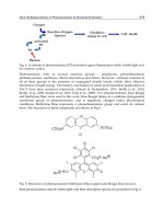
17. DE 40 14 212 C2 (German Patent). C de Oliveira Santos, C Gruner. Effektbasislack
zur Beschichtung von Polypropylensubstraten, May 3, 1990.
18. EP 0 455 211 B2 (European Patent). C Gruner, C de Oliveira Santos. Process of
effect-coating of polypropylene substrates. April 30, 1991.
19. RA Ryntz. Adhesion to Plastics-Molding and Paintability. Global Press, 1998, p
37.
20. C Koevoets, D Nordegraaf, U Hofmann. Leitfaehige Kunststoffe. Kunststoffe 86:
358–360, 1996.
21. W Nowak, A Pothoven. Das smarte Bodypanelsystem. Mannheim, Germany: 1999,
pp 335–337.
22. K Alders. Die lackierung wagenfarbiger anbauteile am beispiel der neuen lackiere-
rei AUDI in ingolstadt. Symposium Praxis Forum, Bad Nauheim, 19/20:85–94,
1998.
23. FL Siever. Anwendungstechnische fragestellungen bei wasserlack. Symposium
Praxis Forum, Bad Neuheim 2/1996, p 10.
24. Brochure Herberts (now DuPont Performance Coatings), Waterborne Basecoat
Technology, 1996.
25. W Ott. In: Erfolgreiches Lackieren von Kunststoffen. Symposium Praxis-Forum,
Bad Nauheim 2/1998.
26. W Hovenstadt, B Klinksiek, M Melchiors. Homogenes Vermischen von waessrigen
2K Polyurethanlacken. Farbe und Lack 106. Jahrgang 7:40–44, 2000.
27. EP 0 800 558 B1 (European Patent). US Patent 5,962,143 October 30, 1996. H
Krauthaeuser, C Gruner, G Huthmacher. Coating composition for producing heat
radiation-reflecting coatings, 30.10.1996.
Index
Acetoacetate, 259 Artificial fingertips, 348
Atomization, high rotation, 344Acrylic resins, 132–133, 135
Additives, 249 Automotive plastic:
coatings, in Europe, 317Adhesion:
cohesive failure, 164 markets, 3
Automotive shredder residue, 269compressive shear delamination, 164
contact angle, 23, 161 Aziridine, 259
-durability balance, 100–101, 103–
106, 109 Basecoats, 263
solventborne, 331failures, 219–221
interfacial binding energy, 23 waterborne, 332–333, 335
application parameters for, 339mold release agents, 161
promoters, 31, 86–87, 95–96, 187 Bezels, 253
Block copolymers, 14surface tension, 161
testing, 26, 164 Blowing agents, 67
Blowing processes, 78, 79thermal shock, 164
wetting, 23 extrusion blow molding, 78
injection blow molding, 79–80work of, 89–90
Alkyds, 48, 51 Blow molding applications, 252
Body seals:Alloys, 247
Amorphous polymers, 246 coatings and, 311
colors, 311Antisqueak coatings, 347
Application parameters for waterborne roles, 310
Bond strength, 92basecoats, 339
353
354 Index
Bumper, 318 [Coatings]
powder, 153coating of, 322
precolored plastics, 62
radiation cured, 149Carbamate, 258
Carbodiimide, 259 surface:
appearance, 62Catalyst, 49
Cathodic electrodeposition, 345 migration, 159
trends, 299Cellulose acetate butyrate (CAB), 332
Center consoles, 253 two-component, 193–195
ultraviolet absorbers, 190–191Charge dissipation, 36–40
Chemical: waterborne, 152
Co-injection molding, 67resistance, 170
treatment, 86 Colorants, 282
Color harmony, 341Chipping, 168
resistance to, 256 Compatibility, 96, 131, 272–273
Composites, 3Chlorinated polyolefins (CPO), 31, 96,
126, 325–326, 329 Conductive carbon black, 110
Conductivity, 110–111, 326Clean Air Act, 254
Amendments, 254 Contact angles, 89, 211–213
Control technique guidelines, 254–255Clearcoats, 264, 344
Coalescence, 153 Conversion:
direct, 50Coatings:
alternates, 279, 297 indirect, 50
Copolymers, 124, 247antisqueak, 347
appearance, 159 Corona treatment, 86, 326
Crockmeter, 170automotive market, 295–296
basecoats, 189–190 Crosslink density, 134
Crosslinkers, 257and body seals, 311
and bumpers, 322 Crosslinking:
binders, 144clearcoats, 190
desirable features, 2 amino resins, 148
polyisocyanates, 145–147exterior, 7
requirements, 298 mechanisms:
carbamate/melamine, 137functions, 294
hindered amine light stabilizers, 190 epoxy/acid, 138
silane, 139–140in-mold, 268, 345
interior requirements, 298 melamine, 94
Crystalline polymers, 246low gloss, 347
multigrain, 312 Crystallization, 126–127
Cure:nonpolluting, 265
(see also Nonpolluting coatings) chemistry, 105
conditions, 108off-line, 318, 331
one-component, 191–193
on-line, 318, 331, 346 Dehumidifying facilities, 337
Die-lock, 66physical properties, 158
of polycarbonate, 329 Directly paintable TPO, 85, 87–88
Index 355
Door applications, 253 Glass transition temperature, 16, 66,
126, 153, 330Dryers, high-temperature radiation, 340
Durability test methodology, 153, 180 Gouging, 165, 221, 236
Harmonic mean model, 90Ecological considerations, 21
Elastomers, 247 Hazardous Air Pollutants (HAPs),
255Electrodischarge machining, 61
Electromagnetic shielding (EMI), 51 Heat:
management, 51Electrostatic painting, 34, 110, 326,
341 stabilizers, 50
Hiding, 264Encapsulation, 72
End-of-life vehicles (ELVs), 269 High-rotation electrostatic spray,
333Energy conversion, 272–273
Environmental etch resistance, 137, 143, Hindered amine light stabilizers, 180
Homopolymer, 247153, 170, 258–259
Environmental regulations, 253–254 Hydrogen bonding, 95
Etch resistance:
clearcoat chemistry, 171 Impact resistance, 168
Injection molding, 64Jacksonville, 170
Evaporation, 337 In-mold coatings, 268, 345
Integrated Pollution Prevention and Con-Extraction procedure, 255
Extrusion, 75 trol (IPPC), 322
Interaction energy, 27compression molding, 290
Interdiffusion, 29
Interfacial energy, 26, 88–91Fillers, conductive, 13, 43–44, 249
Film laminates, 268 Interfacial tension, Young’s equation,
23, 88Flame retardants, 50, 248
spray, 266 Interiors:
acoustics, 300treatment, 86, 324–325, 331, 351
Flexibility tests, 168 barriers, 309
body and glazing seals, 315Flow cups, 335
Fluorine treatment, 325, 327–328 coated fabrics, 309, 315
coextruded films, 314Forming processes, 75
drape forming, 76 door trim panels, 305–308
floor:pressure forming, 77
thermoforming, 55 modules, 308
systems, 315twin-sheet, 77
vacuum forming, 76 instrument panels, 301
molded-in effects, 313plug-assisted, 77
Fox equation, 134 patterns, 312
skins, 303, 312, 314Fuel cell, 275
Functionality, 131 slush molding, 304–305
soft trim fabrication, 301–303
trim, 252Gasoline resistance, 165
Geometric mean model, 90 vacuum forming, 303
Glass fibers, 50 Isocyanate, 258
356 Index
Legislation: Orientation of metallic flake, 342
Oxidation inhibitors, 248ELV, 300
PVC, 300
Light microscope, 222, 234 Paint adhesion, 85, 89, 95–97
Painting processes:Liquid crystalline polymers, 246
Low gloss coatings, 347 application, 204
cleaning, 204
flash and cure, 205Mar and scratch, 136, 150, 154, 221,
236, 256 Paint removal, 271
Paint supply systems, design of, 334Mechanical properties, 171
after weathering, 173 Parison, 79–80
Part economics, 58coating Tg, 172
stresses, 172 capital costs, 60
variable costs, 61Melamine crosslinking, 94
Melting point, 126 Phenolics, 48, 51
Photooxidation, 180–181Melt strength, 55, 80
Metallic flop, 332 durability, 135, 144
Pigments, 50, 262Migration, 161
Miscibility, 88–89 special-effect, 256, 264
Plasma treatment, 86, 351Modulus, 14
Young’s, 18 ambient pressure, 326
low pressure, 325Mold-in color, 248, 283
accents, 283 Plastic classification:
thermoplastics, 244metallics, 284
straight shades, 284 thermosets, 244
Plasticizers, 131Mold release agents, 30
Molecular weight, 121–123, 130 phthalate, 275
Plastic/metal hybrids, 252number average, 123
weight average, 123 Plastic processes:
blow molding, 52, 56, 59MuCell, 253
Municipal waste stream, 272 compression-type, 52, 54, 71–73
extrusion, 52, 54
injection-type, 52Nanotechnology, 248
New curing technology (NCT), 265 liquid injection molding, 53
pull-push processes, 54, 59, 74New enamel technology (NET), 265
No-flame primers, 324 push process, 52, 59
reaction injection molding (RIM), 53Nonpolluting coatings, 265
powder coatings, 266 rotating process, 55, 59
rotational molding, 52, 56supercritical CO2, 267–268
ultraviolet/electron beam, 267 squeeze processes, 53, 59, 71–72, 77,
82Nylon, 70
thermoforming, 52
Plastics, 203Odor, 274
Off-line coating, 318, 331 acrylonitrile/butadiene/styrene (ABS),
8Olefins, 82
On-line coating, 318, 331, 346 conductive modified, 41
Index 357
[Plastics] [Polymers]
phase diagrams, 17conversion processes, 48
engineering, 4 polyamides, 13
poly(ethylene), 48interiors, 13
metallized, 7 processing, 280–282
surface:outgassing, 159
polyamides (PA), 12 analysis, 24–25
properties, 18, 21polycarbonate, 10
polyphenylene oxide (PPO), 12 tension, 29
Polyolefins, 85, 89polyurea, 9
reinforced reaction injection molding Polypropylene, 5
Polyurethane:(RRIM), 189
sheet molding compound (SMC), 8, binders, 142
thermosets, 5189
solvent sensitive, 329 Porosity, 346
Powder coating, 153structural, 3
Plastics by application: Pretreatment, 324
Primers, 189, 263behind the fascia, 250
exterior body panels, 251 conductive, 345
electrically conductive, 328under the hood, 249
Pneumatic spray application, 339 Process capabilities, 57
Processing mechanics, 51Poiseuille flow, 53
Poisson’s constant, 347 Process profiles, 63
Process technology:Polar additives, 102
Polycarbonate, coating of, 329 coextrusion, 285
co-injection molding, 286Polydispersity, 124
Polyester binders, 140, 141, 142 extrusion, 285
injection molding, 285Polyethylene, 5
Polymerization, 48, 121 in-mold processing, 286
molding inserts, 287–290addition process, 49
chain growth, 122 Process window for waterborne base-
coats, 338condensation process, 49
degree of, 123
step growth, 122–123, 142 Radiation cured coatings, 149
Reaction injection molding (RIM), 69,Polymers, 121, 122
acrylonitrile/butadiene/styrene (ABS), 71, 85, 161
reinforced (RRIM), 69–70, 251, 31748
amorphous, 246 structural (SRIM), 70
Reactive diluents, 131, 262architecture, 129
bulk properties, 18 Recyclability, 86, 87
design for, 270conductive modified, 35
crystalline, 246 dismantlability, 270
Recycling, 243engineering, 14
glass transition temperature, 19 criteria, 269
Reinforced reaction injection moldingliquid crystalline, 246
nylon 6/6, 49 (RRIM), 69–70, 251, 317
358 Index
Reinforcing fibers, 249 [Substrate]
scratch and mar, 186Replenishing tank, 343
Resin transfer molding, 72–74 thin-walled TPO, 186
Superacids, 150Rheology:
characteristics, 336 Surface appearance, class A, 75, 80
Surface contamination, 29control agents, 262
Rotational molding, 81–82 Surface defects:
bondline readout, 209–210
color, 218Scratch, 169
Segregation of molded-in color, 271, convection flow, 210
craters, 206–207272
Sheet molding compound (SMC), 54, dewetting, 207–208
dirt, 216–21872, 250–251, 269, 320, 345–
346, 351 fiber read-through, 209
flow related, 215–216gassing, 233
Silane, 259 gassing, 214
micropopping, 214Silicones, 161
Skins, 253 picture framing, 210
surface tension driven, 205Slido, 166–167
Soft feel, 252 telegraphing, 208–209, 232
volatile related, 213Soft touch, 143, 347–350
Solvency, 130 Surface energy, 87, 89, 96, 99
Surface functionalization, 33Spray booths, 318
Stabilizers, 153 Surface morphology, 30
Surface tension, 26, 324, 342hindered amine light, 154, 180, 344
thermal, 248 gradients, 232
liquids, 89ultraviolet absorbers, 154, 190–191,
248, 344 polymers, 29
Surface treatment, 31–32Stereo regularity, 322
Stiffness, 107 plasma, 31
Stone chipping, 221
Stress levels, 63 Taber abrader, 117
testing, 170Structural foam molding, 67
Structural reaction injection molding TA Luft regulation, 321
Thermoform coextruded sheets, 290(SRIM), 70
Substrate: Thermogravimetric analysis, 232
Thermoplastic olefins (TPO), 5, 85–87,adhesion, 184
appearance, 182 89, 91, 186, 317
coating process, 323chipping, 185
durability, 182 Thermoplastics, 50–51, 78, 80, 128
Thermosets, 50–51, 73etch and chemical resistance,
187 Thin-walled molding, 322
Tie-layer, 86–87flexibility, 185
gasoline resistance, 184 Tooling, 66
Toxicity characteristic, 255gouging, 184
impact resistance, 185 Transfer efficiency, 34, 36, 39, 110
Index 359
Ultraviolet (UV): [Weathering]
carbon arc, 179absorbers, 180, 220, 282
light treatment, 86 durability, 174
emmaqua, 179resistance, 110–111
stabilizers, 50 natural, 173
quartz ultraviolet (QUV), 178–Uretdiones, 147
Urethanes, 48, 70, 85 179
xenon arc, 176–178crosslinking, 94
Wetting, 211
adhesion, 228Viscosity, 128, 342
measurement, 233 contact angles, 225, 229
critical surface tensions, 223Volatile organic compound (VOC), 86–
87, 254, 263, 265, 321 dewetting tests, 230
solid surface tensions, 226–228
tests, 223Waterborne coatings, 152
Wave scan, 321 Zisman plots, 224, 230
Work of adhesion, 89–90Weak boundary layers, 30
Weathering:
accelerated, 176 Young’s equation, 23, 88
колхоз
11/13/06