Carbon Materials for Advanced Technologies Part 5 doc
Bạn đang xem bản rút gọn của tài liệu. Xem và tải ngay bản đầy đủ của tài liệu tại đây (706.43 KB, 35 trang )
120
composed of rigid molecules, the as-spun fiber does not achieve a stacking
arrangement which is graphitizable over a long range. Thus, the tensile modulus
and thermal conductivity of PAN-based carbon fibers do not achieve values
comparable to mesophase pitch-based fibers. The repeat unit
of
polyacrylonitrile
is shown in Fig.
1.
In
reality,
PAN
is
an atactic polymer; that is, the nitrile groups
are randomly positioned with respect to the polymer backbone.
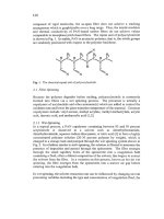
Fig.
1.
The
chemical
repeat
unit
of
polyacrylonitrile.
2.1
Fiber
Spinning
Because the polymer degrades before melting, polyacrylonitrile
is
commonly
formed into fibers via a wet spinning process. The precursor is actually a
copolymer
of
acrylonitrile and other monomer(s) which are added to control the
oxidation rate and lower the glass transition temperature of the material. Common
copolymers include vinyl acetate, methyl acrylate, methyl methacrylate, acrylic
acid, itaconic acid, and methacrylic acid
[
1,2].
2.1.1
Wet-Spinning
In a typical process, a
PAN
copolymer containing between
93
and
95
percent
acrylonitrile is dissolved in a solvent such as dimethylformamide,
dimethylacetamide, aqueous sodium thiocyanate, or nitric acid
[3] to
form
a highly
concentrated polymer solution
(20-30
percent polymer by weight), which is
charged to
a
storage
tank
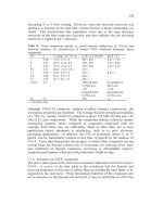
and pumped through the wet spinning system
shown
in
Fig.
2.
In
a fashion similar
to
melt-spinning, the solution
is
filtered to
minimize
the
presence of impurities and passed through the spinnerette. The fiber emerges
through the small capillary holes of the spinnerette into a coagulation bath
containing a fluid,
ofien
a diluted composition of the solvent, that begins to extract
the solvent
from
the fiber. In a variation
on
this process,
known
as dry-jet wet
spinning, the fiber emerges
from
the spinnerette into a narrow air gap before
entering into the coagulation bath.
In
wet
spinning,
the solvent extraction
rate
can be influenced by changing several
processing variables including the type and concentration of coagulation fluid, the
121
temperature of the bath, or the circulation rate
of
fluid within the bath.
bath
bath bath
Drv
and
heat&-draw
n
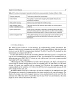
Fig.
2.
Wet-spinning
of
PAN
fibers (adapted from
[4]).
Controlling the extraction rate is vital because the shape and texture of the resultant
fiber is directly influenced by the solvent removal rate. As the solvent is extracted
from
the surface of the fiber, significant concentration gradients can form. These
gradients may result
in
a warping of the desired circular shape
of
the fiber. For
example, if the solvent is removed too quickly, the fiber tends
to
collapse into a
dog-bone shape.
Additionally, the solvent extraction rate influences the
development
of
internal voids or flaws in the fiber. These flaws limit the tensile
strength of the fibers.
The gel fiber that emerges
from
the coagulation bath always undergoes a series
of
washing, drawing, and drying steps, during which the fiber collapses into its final
form. Much
of
the internal morphology
is
developed as a result
of
these processes
[3].
Normally, a finish is applied to aid in fiber handling.
2.1.2
Alternative Spinning Technologies
A variation on the wet-spinning technique involves extrudmg into a heated gas
environment.
In
this
dry-spinning process, the temperature and composition of the
gas control the extraction process.
Although solution spinning provides high quality
PAN
fibers, it presents
a
significant disadvantage. Solution spinning requires the use of a large quantity
of
an organic or inorganic solvent. This creates the need
for
efficient solvent
recovery, adding additional complexity and cost to the process. Therefore, other
spinning strategies have been investigated.
The use of a wet-spinning process with inorganic solvents has
also
been attempted.
Although the details of this process are proprietary, it is clear that these inorganic
wet-spun PAN fibers make higher quality carbon fiber precursors than those
produced with traditional organic solvents
[5].
122
Another approach to eliminate the need for organic solvents was explored in the
late eighties by
BASF
Structural Materials, Inc.
[6].
In
their process, the
acrylonitrile and other co-monomers are polymerized
in
an
aqueous solution. Next,
the resultant slurry is purified, and most
of
the excess water is removed. The
copolymer then
is
pelletized and fed to an extruder. The remaining water in the
pellets serves to plasticize the polymer and enables it to form a homogeneous melt
below its degradation temperature. The melt is extruded through a multiple hole
spinnerette into a steam-pressurized solidification zone.
In
addition to eliminating
the need
for
organic solvents,
this
melt-assisted spinning process provides a more
unifm fiber because of the
enhand
polymer content
of
the plasticized
PAN
[7].
2.2
Stabilization
The as-spun acrylic fibers must be thermally stabilized
in
order to preserve the
molecular structure generated as the fibers are
drawn.
This
is
typically performed
in air at temperatures between
200
and
400°C
[SI.
Control
of
the heating rate is
essential, since the stabilization reactions are highly exothermic. Therefore, the
time required to adequately stabilize
PAN
fibers can be several hours, but will
depend
on
the
size
of
the fibers, as well as
on
the composition
of
the oxidizing
atmosphere. Their are numerous reactions that occur during this stabilization
process, including oxidation, nitrile cyclization, and saturated carbon bond
dehydration
[7].
A
summary
of several functional groups which appear
in
stabilized
PAN
fiber can be seen in Fig.
3.
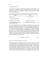
Fig.3
Illustration
of
functional groups appearing
in
stabilized
PAN
fiber
[9].
123
There is recent evidence that stabilization to elevated temperatures (over 350°C)
yields a structure with additional intermolecular cross-linking that results in
improved mechanical properties in carbonized fibers
[
10,111. In addition, it has
been noted that the addition of
ammonia
to the stabilizing environment accelerates
stabilization [12].
2.3 Carbonization
The stabilized fiber is carbonized in an inert atmosphere to temperatures ranging
from 1000-3000"C, driving of virtually all non-carbon elements. There
is
a
substantial mass loss associated with this pyrolysis.
In
fact, the yield of carbon
fiber upon carbonization of PAN is typically in the range of 40-45% [13].
Controlling the heating rate is essential in preventing the formation of defects as
the volatile gases are removed. A decrease in tensile strength with carbonization
beyond 1500°C is usually observed [14]. For this reason, the highest strength
PAN-based carbon fibers often contain residual nitrogen. Tensile modulus, by
contrast, continues to rise with heat treatment temperature. Heat treatment beyond
1700°C is often termed graphitization; however, the term may only be loosely
applied to PAN-based fibers, which are not, strictly speaking, graphitizable.
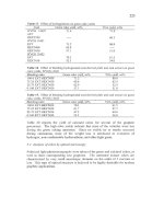
2.4 Fiber Microstructure
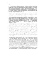
Diefendorf and Tokarsky
[
151 have shown that PAN-based carbon fibers develop
a fibrillar microstructure. The microstructure of the PAN-based fibers, shown in
a schematic model in Fig,
4,
may be viewed as regions of undulating ribbons.
Th~s
structure is much more resistant to premature tensile failure resulting
from
microscopic flaws
than
microstructures exhibiting more extended graphtic regions
transverse to the fiber axis, such as those seen in mesophase pitch-based carbon
fibers. Thus, PAN-based fibers tend to develop exceptional tensile strengths, but
are less suited for developing high tensile moduli.
3
Carbon Fibers
from
Mesophase Pitch
A relatively new class of high-performance carbon fibers
is
melt-spun from
mesophase pitch, a discotic nematic liquid crystalline material. This variety
of
carbon fibers
is
unique in that it can develop extended graphitic crystallinity during
carbonization, in contrast to current carbon fibers produced from PAN.
3.1 Mesophase Formation
The mesophase pitches used for high-modulus carbon fiber production can be
formed either by the thermal polymerization of petroleum- or coal tar-based
124
pitches, or by the catalytic polymerization
of
pure compounds such as naphthalene.
The mesophase transformation results in an intermediate phase, formed between
400°C and
550"C,
during the thermal treatment of aromatic hydrocarbons. During
mesophase formation, domains
of
highly parallel, plate-like molecules form and
coalesce
until,
with time, a 100% anisotropic material may
be
obtained. It
has
been
well-established that, when mesophase pitch
is
carbonized, the morphology of the
pitch
is
the primary factor
in
determining the microstructure of the resulting
graphitic material.
Fig.
4.
Illustration
of
the
fibrillar
texture of
a
carbonized
PAN
fiber
[15].
3.1.1
Pyrolysis
of
Petroleum or Coal Tar Pitch
Raw pitch, a high molecular weight by-product formed during petroleum or coal
refining operations,
is
composed
of
a
rather broad mixture
of
hundreds of
thousands of organic species with an average molecular weight
of
several hundred.
Many
of
these species are heterocyclic, contain highly aromatic components, and
are formed by a variety of thermal decomposition, hydrogen transfer, and
oligomerization reactions
[16].
In
the United
States,
pitch derived from petroleum
has been the only graphitizable carbon fiber precursor employed commercially.
Petroleum pitch
is
commonly formed from the heavy gas
oil
fraction
of
crude oil
[17].
During gas oil cracking, a heavy by-product called decant oil
is
formed.
This
decant
oil
is often used as fuel oil; however, because of its high aromaticity, it may
be pyrolyzed to
form
pitch.
125
Often, pitches and oils are classlfied into four general fractions: saturates,
naphthene aromatics, polar aromatics, and asphaltenes
[
131. The saturates are the
lowest molecular weight fraction and are aliphatic. Naphthene aromatics consist
largely of low molecular weight aromatic species. Polar aromatics are larger
molecules and may be heterocyclic. Lastly, the asphaltenes are large, plate-like,
aromatic molecules which
often
possess aliphatic side-groups. Oils are composed
mostly of saturates and naphthene aromatics, while pitches are often rich in
asphaltenes. Since the asphaltenes have a high molecular weight and are highly
aromatic, raw petroleum pitches which contain a high percentage of asphaltenes
(e.g.,
Ashland-240, Ashland-260) are often selected as feed stocks for the
formation of mesophase. However, the asphaltic residuum fraction of crude oil
is
not used for pitch production, due to the presence of metallic impurities and
structures which are not plate-like in this fraction.
A mesophase can be produced by the heating of a highly aromatic pitch
in
an inert
atmosphere for an extended period of time. The mesophase transformation was
first observed by Brooks and Taylor
6181
as an intermediate phase of spherules
with mosaic structures, formed between 400°C and 550°C during the thermal
treatment of aromatic hydrocarbons. It was found that a wide range of materials,
such as coals, coke-oven pitch, petroleum
tar,
bitumen, polyvinyl chloride,
naphthacene, or dibenzanthrone, will
form
similar structures which precipitate fiom
the isotrapic phase during prolonged pyrolysis. Selected-area electron diffraction
patterns indicated that each mesophase sphere possesses at its center a single
direction of preferred orientation. As the pyrolysis continues, the spherules tend
to grow and coalesce
until
a phase inversion takes place, after which the mesophase
becomes the continuous phase
[
191.
It has been established that, when mesophase pitch is carbonized, the morphology
of the pitch is the primary factor
[20]
in determining the microstructure of the
resulting graphitic material. This may be attributed to the stacking behavior
of
mesophase molecules (quite similar to the planar stacking in turbostratic graphite),
which may be visualized as shown
in
Fig.
5.
In the years following the Brooks and Taylor dwovery, many researchers
attempted to produce a mesophase pitch suitable for carbon fiber production.
Otani
et
al.
[21]
were fit to report producing a high-modulus carbon fiber from a
"specific pitch-like material." The precursor used was tetrabenzophenazine, and
thus, the resulting material might be considered a synthetic pitch.
Singer [22] developed a process for converting
50%
of low-cost Ashland 240
isotropic pitch to mesophase by heating the pitch to 400-410°C for approximately
40
hours.
During this ''heat-soak," mesophase tended to collect at the bottom of the
vessel, due to its greater density. The production
of
highly-oriented, graphitizable
126
fibers was possible after
55-65
weight
%
mesophase was formed. Lewis
[23]
discovered that a more uniform (and thus, more spinnable) product could be
obtained by agitating the pitch during the pyrolysis, forming a homogeneous
emulsion of the mesophase and isotropic components. Chwastiak and Lewis
[24]
were able to produce a
100%
(bulk)
mesophase product by using
an
inert gas to
agitate the reactive mixture and remove the more volatile components.
Otani
and
Oya
[25]
have reported that a lower softening (more spinnable) product may be
obtained if a hydrogenation step is added either before or after mesophase
formation.
A
typical molecule of a heat-soaked mesophase is illustrated
in
Fig.
6.
Fig.
5.
Schematic illustration
of
mesophase stacking arrangement (adapted
from
[20]).
Mol
1178
ClH-
1.50
Fig.
6.
Typical molecule
of
a heat-soaked mesophase (adapted
from
[26]).
127
3.1.2 Solvent Extraction
Mesophase also can be produced via a solvent extraction technique. Diefendorf
and Riggs [27] have shown that an isotropic pitch, such as Ashland 240 or Ashland
260, can be converted to mesophase by first extracting a portion of the pitch with
a solvent, such as benzene, toluene, or heptane. The insoluble portion then is
pyrolyzed for only ten minutes in the range of 230°C to 400°C, yielding a product
which is from 75 to
100%
mesophase. While this process greatly reduces the
required heat treatment time, the benefit is offset by the potential handling hazards
and the high cost of these organic solvents. Furthermore, if the volatile
components are not completely removed, spinning can be difficult.
3.1.3 Novel Processes
Both the heat-soaking process (developed at the Union Carbide Corporation and
later utdized by Amoco Performance Products) and solvent extraction process
(patented by Exxon Research and Engineering Co. and later practiced by
E,
I.
du
Pont de Nemours and
Co.)
convert a natural (petroleum) pitch feed to a mesophase
product. Their primary advantage is that the natural pitch feed stock
is
inexpensive,
as
it has little other practical value. However, there are three
si&icant disadvantages in using natural pitch as a carbon fiber precursor. First,
pitch is a broad mixture, making spinning difficult to control. Also, the
composition of the pitch feed stock may vary from day to day, since it is a by-
product of a very complex process and is, itself, refined from a variable feed stock
(crude oil). A third problem is that in every step of pitch production, refining, and
subsequent mesophase formation, a heavy fraction
is
collected. This means that
impurities, which are inevitably present, are sequentially concentrated. The result
is a reduction in tensile strength of pitch-based fibers due to inclusions, even after
extensive filtration.
These problems have spurred interest
in
alternate methods of mesophase formation.
Hutchenson
et
al.
[28] have reported that supercritical fluid (SCF) extraction can
be employed to fractionate pitch. By continuously varying pressure or temperature
(and, thus, solvent strength), selective pitch fractions of relatively narrow molecular
weight distribution can be isolated. Such a process offers the potential of
producing a uniform product from a changing feed stock. Furthermore, since the
heaviest fraction
is
not the only one which yields a bulk mesophase, it
may
be
possible to produce a mesophase fraction largely free of impurities. In fact, highly
spinnable fractions have already been isolated and used to produce carbon fibers
with strengths exceedmg 3 GPa and moduli exceeding
800
GPa [29].
Another method which might avoid the problems associated with natural pitch
feeds involves producing mesophase from a synthetic precursor. Recently,
Mochida
et
al.
[30] developed a process in which mesophase is produced by the
polymerization of naphthalene or methyl naphthalene, with the aid of a HFBF3
128
catalyst.
HF/BF3
has been studied as a Bronsted acid "super catalyst"
in
applications such as coal liquefaction and aromatic condensation.
Its ability to
polymerize aromatic hydrocarbons, however,
has
only recently been utilized to
produce mesophase. The resultant aromatic
resin
(AR)
mesophase (Mitsubishi Gas
Chemical
Co.,
Inc.)
is
reported to be more spinnable and more easily oxidized than
the mesophase formed by heat-soaking raw pitch. Furthermore, Mitsubishi Gas
Chemical
Co.
has
claimed that the properties
of
the
find
carbonized
AR
fibers are
comparable to those
of
the best commercial mesophase fibers.
3.2
Melt-Spinning
The manufacturing
of
carbon fibers from mesophase pitch is accomplished in three
steps: melt-spinning, oxidative stabilization, and carbonization (see Fig.
7).
The
peculiar difficuties encountered during spinning and heat treating mesophase pitch
fibers result
in
a high processing cost for
this
class
of
fiber. Conversely,
improvements in precursor quality and processing technology offer the best
opportunity to reduce the price of these high-performance fibers.
n
Melt
Spinning
8
n
Carbonization
Surface
Si
product
Treatment
Fig.
7.
Processing
of
carbon fibers
from
mesophase
pitch.
The melt-spinning process used to convert mesophase pitch into fiber form is
similar
to that employed for
many
thermoplastic polymers. Normally, an extruder
melts the pitch and pumps it into
the
spin pack. Typically, the molten pitch is
filtered before being extruded through a multi-holed spinnerette. The pitch is
subjected to high extensional and shear stresses as it approaches and flows through
the spinnerette capillaries. The associated torques tend to orient the liquid
crystalline pitch
in
a regular transverse pattern. Upon emerging from the
129
spinnerette capillaries, the as-spun fibers are drawn to improve axial orientation
and collected on a wind-up device.
3.2.1 Mesophase Pitch Rheology
To date, there has been relatively little work reported on the mesophase pitch
rheology which takes into account its liquid crystalline nature. However, several
researchers have performed classical viscometric studies on pitch samples during
and after their transformation to mesophase. While these results provide no
information pertaining to the development of texture in mesophase pitch-based
carbon fibers, this information is of empirical value in comparing pitches and
predicting their spinnability,
as
well as predicting the approximate temperature at
which an untested pitch may be melt-spun.
Nazem [3 11
has
reported that mesophase pitch exhibits shear-thinning behavior at
low shear rates and, essentially, Newtonian behavior at higher shear rates. Since
isotropic pitch is Newtonian over a wide range of shear rates, one might postulate
that the observed pseudoplasticity of mesophase is due to the alignment of liquid
crystalline domains with increasing shear rate. Also, it
has
been reported that
mesophase pitch can exhibit thixotropic behavior [32,33]. It is not clear, however,
if
thls
could be attributed to chemical changes within the pitch or, perhaps, to
experimental factors.
A very unusual characteristic of mesophase pitch is the extreme dependency of its
viscosity on temperature [19,34,35]. This factor
has
a profound influence on the
melt-spinning process (described above), as a mesophase pitch fiber will achieve
its
final
diameter within several millimeters of the face of the spinnerette,
in
sharp
contrast to most polymeric fibers.
3.2.2 Liquid Crystal Flow and Orientation
The rigid nature of the mesophase pitch molecules creates a strong relationship
between flow and orientation. In this regard, mesophase pitch may be considered
to be a discotic nematic liquid crystal. The flow behavior of liquid crystals of the
nematic
type
has been described by a continuum theory proposed by Leslie [36]
and Ericksen [37].
The conservation equations developed by Ericksen [37] for nematic liquid crystals
(of
mass, linear momentum, and angular momentum, respectively) are:
(V.v)=O,
130
av
at
p-=
-p(v*Vjv-VP
+[o.T],
[n-h]
=(a3
-a2)[n.N]
+(az+a3)[n*[A
*n]].
(3)
where
v
is the velocity,
zis
the viscous stress tensor,
P
is
the pressure,
p
is
the fluid
density,
N
is the director motion vector,
A
is the rate of deformation tensor, the
ai
values are viscosity coefficients, and
h
is the molecular field.
Leslie
[36]
developed a general expression for the viscous stress,
~=a~n(n*[A*n])n
+a,nN+a,Nn
+a%
+a5n[n.A]
+a6[n;4]n.
(4)
The rate of deformation and the director motion vector are
(5)
1
2
A
=-([VV]
+[VV]'),
Five of the six coefficients are independent, because
of
the constraint [38]
a -a
=a2+a3
65
The molecular field appearing in equation
(3)
can be approximated by
where
K
is
an
average elastic constant.
The above equations have been solved
to
predict the commonly observed radial
and line-origin textures seen in circular and non-circular mesophase pitch-based
carbon fibers
[39].
3.2.3
Spinning Conditions
As
the basic fiber microstructure is determined during the spinning and drawing
processes, several spinning process variables have a significant impact on fiber
properties
(e.g.,
flow rate, winder speed, spinnerette geometry, etc.). Spinning
13
1
temperature, in particular,
has
been shown to greatly affect the degree of preferred
orientation within the fiber [40,41] as well as its carbonized properties (42,431.
Unfortunately, the range of temperatures over which a mesophase pitch fiber can
be melt-spun
is
rather narrow, due to the strong viscosity-temperature relationship
of the material.
3.3
Stabilization
The as-spun mesophase pitch fiber is extremely weak and must be heat-treated to
develop
its
ultimate mechanical properties. The first step in this process involves
fiber oxidation, more descriptively called stabilization. The purpose of oxidation
(similar to
PAN
fibers) is to prevent the fiber
from
melting during the subsequent
carbonization treatment, thus
to
"lock in" the structure developed during the
extrusion process. Typically, stabilization
is
accomplished by exposing the fibers
to flowing air at a temperature of approximately
300°C
for a period of time ranging
from several minutes to a few hours, depending on the precursor, the fiber size, and
the exact temperature employed. The final oxidation temperature can be slightly
above the softening point of the pitch, if a slow heating rate is used to ensure some
degree of oxidation before the softening point is exceeded. Because of the length
of time required, the oxidation process adds significantly to the overall processing
cost for mesophase pitch-based carbon fibers.
During the oxidation process, oxygen tends to react fmt
with
aliphatic side-groups,
cross-linking and adding weight to the fiber.
For
this
reason, a convenient method
to characterize the extent of oxidation is thermogravimetric analysis (TGA).
Stevens and Diefendorf [44] have reported that a 6% weight gain is required to
completely stabilize the fiber. However, Matsumoto and Mochda [45] showed that
the uniformity of oxygen pick-up also must be considered if tensile properties are
to be maximized. They found that a high degree of uniformity can be achieved if
lower heating rates and lower final temperatures are employed. This uniform
stabilization, of course, must be balanced by the associated increase in processing
costs.
3.4
Carbonization and Graphitization
Once the fibers have been adequately stabilued, carbonization is possible. During
this step the fibers are heated in an inert atmosphere
to
temperatures of up
to
3000
"
@,
driving off all non-carbon elements. Typically, carbonization proceeds
in
two
stages. During the first (precarbonization) stage, the fibers are brought to
and often held at
1OOO"C,
allowing the majority of the weight
loss
to
occur
(mostly
as
CH4, H2, and
Cq).
Singer and Lewis [46] claim that the rate limiting
step in this low-temperature carbonization
is
the breakage
of
carbon-hydrogen
bonds by a free-radical process and that the amount of hydrogen evolution (the free
132
radical concentration) is related to the size of the growing aromatic molecules.
Subsequently, the fibers are carbonized at higher temperature to obtain the high
strength, high modulus carbon fiber. By convention, heat treatment at temperatures
above 1700°C is termed "graphitization."
At these temperatures, the fiber is
virtually all carbon, thus, mostly structural changes take place. During
graphitization, dislocations in the initially disordered carbon stacks are annealed
out, eventually resulting
in
the formation of a three-dimensional graphite lattice.
The graphitization process primarily involves atomic diffksion and crystallite
growth
[47].
3.5
Observed Fiber Microstructures
The properties of mesophase pitch-based carbon fibers can vary significantly with
fiber texture. Inspection of the cross-section of a circular mesophase fiber usually
shows that the graphitic structure converges toward the center of the fiber. This
radial texture develops when
flow
is fully developed during extrusion through the
spinnerette. Endo
[48]
has shown that this texture of mesophase pitch-based
carbon fibers is a direct reflection
of
their underlying molecular structure.
Commonly, the texture is not perfectly radial and some degree
of
folding of the
crystallites is observed.
Thls
appears to improve the fiber's resistance to crack
propagation and, thus, increases its tensile strength. Folding is an arhfact of
disclinations
in
the precursor pitch which may, to a lesser extent, remain after
spinning (if inadequate time is allowed for reorientation
[49,50]).
Fibers also can
be formed with no clearly defined texture. Creation
of
a random texture involves
complete disruption of the developing flow (for example, by spinning through
capillaries containing porous media
[51],
and such fibers offer the potential of
improved compressive strengths.
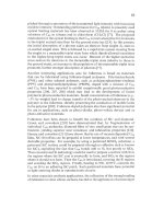
Production
of
fibers with a concentric, or "onion-skin," texture has also been
reported, but it is difficult to postulate a single mechanism
to
explain the
occurrence of this texture. Matsumoto
[
141
reports that extrusion through a large
diameter capillary can yield fibers with
a
concentric texture. Hamada
et
al.
[52]
formed onion-skin fibers by stirring the pitch upstream fiom the capillary and, thus,
inducing a tangential velocity component. Mochida
et
al.
[53]
have been able
to
produce fibers with a concentric texture at very high spinning temperatures (low
spinning viscosities). Edie
et
al.
[54]
have found that spinning through non-
circular channels yields fibers with a highly linear "line-origin" texture. Each of
these textures is illustrated in Fig.
8.
133
wal
Onion-skin
Random
Flat-layer
Radial-folded
Line-origin
Fig.
8.
Observed textures
of
mesophase pitch-based carbon fibers (adapted
from
[55]).
4 High Performance Carbon Fibers from Novel Precursors
Recently, the use of high performance polymeric fibers as carbon precursors
has
been investigated. For example, it has been found that rigid-rod polymers such as
poly p-phenylene terephthalamide (Kevlar@) or poly p-phenylene benzobisoxazole
(PBQ)
can be converted to carbon fibers without the need for the expensive
stabilization process
1561.
This
is
due
to the lllghy aromatic nature of the polymer
backbones which makes these materials impervious to melting. Although research
into using high-performance polymers as carbon fiber precursors continues, there
are currently
no
commercial applications for these materials.
5
Carbon Fiber Property Comparison
PAN
fibers develop a structure
with
little point-to-point relations@ between atoms
in
neighboring basal planes. This structure
is
labeled the turbostratic configuration
and is characterized by interplanar spacing values greater than
0.344
nm.
The
crystallite size
in
the direction normal to the basal planes, or stack height
(LJ,
in
turbostratic graphite is typically less than
5
nm.
134
Since PAN-based carbon fibers tend to be fibrillar in texture, they are unable to
develop any extended graphitic structure. Hence, the modulus of a PAN-based
fiber is considerably less than the theoretical value (a limit which is nearly achieved
by mesophase fibers), as shown in Fig.
9.
On the other hand, most commercial
PAN-based fibers exhibit higher tensile strengths than mesophase-based fibers.
This can be attributed to the fact that the tensile strength of a brittle material is
controlled by structural flaws
[58].
Their extended graphitic structure makes
mesophase fibers more prone to this type of flaw. The impure nature of the pitch
precursor also contributes to their lower strengths.
PAN
Mesophase
I
I
I
'New Gemtion"
-carbonized
above
2000°C
I
I I
I
I
I
I
I
I
0
100 200
300
400
500
600
700
800
900
lo00
Fiber
Modulus
(GPa)
Fig.
9.
Tensile strength
versus
modulus
for
some commercial carbon fibers (adapted
from
W1).
6
Current Areas for High Performance Carbon Fiber Research
Much of the current interest surrounding high performance carbon surrounds their
potential for use in thermal management applications. Since some grades of
mesophase pitch-based fiber have thermal conductivities three times that of copper,
composites fabricated with these fibers are ideal for reducing thermal gradients.
The ability to dissipate heat is an important factor in both structural composites and
electronic systems. It has been found that spinning pitch fibers of a ribbon-shape
is more conducive to developing high thermal conductivity
[59].
The potential for
this
market has contributed to the continued interest in furthering understanding
of
135
structural development during melt-spinning
[60,61].
These studies have
demonstrated the complex nature of the shear and elongational flow of mesophase.
In
contrast, there is also current interest in investigating PAN-based fibers in low
thermal conductivity composites
[62],
Such fibers are carbonized at low
temperature and offer a substitute to rayon-based carbon fibers in composites
designed for solid rocket
motor
nozzles and exit cones.
7
Summary and Conclusions
Although it is clear from the above discussion that there are many similarities in the
processing techniques used for all continuous carbon fibers, the structure and
properties of the final products are highly variable, depending on the chemical
nature
of
the precursor. Since PAN-based fibers are turbostratic in nature, they are
limited in developing ultra-high stifkesses or thermal conductivities, but the
absence
of
large graphitic crystallites is well-suited for developing extremely high
strength. Mesophase pitch fibers, by contrast, are graphitizable and can develop
extremely high stiffnesses and thermal conductivities. Unfortunately, the large
crystallites necessary to develop these properties carry a cost in tensile strength.
Further improvements in the properties of PAN-based carbon fibers are likely to
emerge through improved stabilization, that
is,
by creating the ideally cross-linked
fiber. On the other hand, as purer pitch precursors become available, further
improvements in mesophase pitch-based carbon fibers are likely to arise from
optimized spinnerette designs and enhanced understanding of the relationship
between pitch chemistry and its flowlorientation behavior. Of course, the
development
of
new precursors offers the potential to form carbon fibers with a
balance
of
properties ideal for a given application.
8
References
1.
2.
3.
4.
5.
Runham,
M.
G.,
Stabilization
of
polyacrylonitrile carbon fiber precursors. Ph.D.
dissertation, Clemson University, Clemson, SC,
1990.
Jain,
M.
K.
and Abhiraman,
A.
S.,
Conversion
of
acrylonitrile-based precursor fibres
to
carbon fibres,
JMat Sci,1987,22(1), 278
300.
Capone, G. J., Wet-spinning technology. In
Acrylic Fiber Technology and
Applications,
ed.
J.
C. Masson. Marcel-Dekker, New York,
1995,
pp.
69 103.
Ram,
M
J.
and Riggs,
J.
P., US Patent
No.
3,657,409, 1972.
Fitzer,
E.,
PAN-based carbon fibers
-
present state and trend
of
the technology
from
the viewpoint
of
possibilities and limits to influence and to control the fiber properties
by the process parameters,
Carbon,
1989,27(5), 621 645.
136
6.
7.
8.
9.
10.
11.
12.
13.
14.
15.
16.
17.
18.
19.
20.
21.
22.
23.
24.
Daumit, G. P. and KO, Y. S., A unique approach to carbon fiber precursor
development. In High Tech-The Way Into the Nineties, ed.
K.
Brunsch et al. Elsevier
Science, Oxford, 1986, pp. 201 213.
Edie,
D.
D. and Diefendorf, R. J., Carbon fiber manufacturing.
In
Carbon-Carbon
Materials and Composites, ed.
J.
D. Buckley and D.
D.
Edie. Noyes Publications,
Park Ridge, NJ, 1993, pp. 19 39.
Peebles, L.
H.,
Carbon fibers from acrylic precursors. In Carbon Fibers: Formation,
Structure, and Properties. CRC Press,
Boca
Raton, FL, 1995, pp. 7 26.
Clarke, A.
J.
and Bailey, J.
E.,
Oxidation of acrylic fibres for carbon fibre formation,
Nature, 1973, 243(5402), 146 154.
Mathur,
R.
B.,
Bahl,
0.
P. and Mittal, J.,
A
new approach to thermal stabilisation
of
PAN fibres, Carbon, 1992,30(4), 657 663.
Mittal,
J.,
Bahl,
0.
P., Mathur,
R.
B. and Sandle, N.
K.,
IR
studies of PAN fibres
thermally stabilized at elevated temperatures, Carbon, 1994,32(6), 1133 1136.
Bhat, G.
S.,
Cook, F. L., Abhiraman, A.
S.
and Peebles, L. H., New aspects in the
stabilization of acrylic fibers for carbon fibers, Carbon, 1990, 28(2/3), 377 385.
Riggs, D.'M., Shuford, R. J. and Lewis, R. W., Graphite fibers and composites. In
Handbook
of
Composites, ed. G. Lubin. Van Nostrand Reinhold Co., New York,
1982, pp. 196 271.
Matsumoto, T., Mesophase pitch and its carbon fibers, Pure
&
Appl Chern, 1985,
57(11), 1553 1562.
Diefendorf,
R
J. and Tokarsky, E., High performance carbon fibers,
PoZym
Eng
Sci,
1975, 15(3), 150 159.
Singer, L.
S.,
The mesophase in carbonaceous pitches, Faraday
Disc
Chem
Soc,
1985,
79,265 272.
Romine,
H.
E.,
Petroleum pitch. Presentation at Clemson University, Clemson, SC,
3 December, 1987.
Brooks, J.
D.
and Taylor, G.
H.,
Formation of graphitizing carbons from the liquid
phase, Nature, 1965,206, 697 699. Carbon, 1965,3(2), 185 193.
Rand,
B., Carbon fibres from mesophase pitch. In Handbook
of
Composites,
VoZ.
I:
Strong Fibres, ed. W. Watt and B. V. Perov. North-Holland, Amsterdam, 1985, pp.
495 575.
Zimmer, J.
E.
and White,
J.
L., Disclination structures
in
the carbonaceous
mesophase.
In Advances
in
Liquid Crystals,
Vol.
5, ed.
H.
G. Brown. Academic
Press,
New
York, 1982, pp. 157 213.
Otani,
S.,
Kokubo, Y. and Koitabashi, T., The preparation
of
highly-oriented carbon
fiber from pitch material,
Bull
Chem
Soc
Japan, 1970,43(10), 3291 3292. Otani,
S.,
Watanabe,
S.,
Ogino,
H.,
Iigima,
K.
and Koitabashi, T., High modulus carbon fibers
from pitch materials,"
Bull
Chem SocJapan, 1972,45(12), 3710 3714.
Singer, L.
S.,
High modulus high strength fibers produced .from mesophase pitch,
U.
S.
Patent 4,005,183, 1977.
Lewis, I. C.,
US
Patent
No.
4,032,430, 1977.
Chwastiak,
S.
and Lewis,
I.
C., Solubility
of
mesophase pitch, Carbon, 1978,16(2),
156 157.
137
25.
26.
27.
28.
29.
30.
31.
32.
33.
34.
35.
36.
37.
38.
39.
40.
41.
42.
43.
44.
Qtani,
S.
and Oya,
A,,
Progress
of
pitch-based carbon fibers
in
Japan, ACS Symp Ser,
1986,303(22)
(Petroleum-Derived Carbons),
323 334.
Fitzer, E., Kompalik, D. and Mayer, B., Influence
of
additives on pyrolysis
of
mesophase pitch.
In
Carbon
'86:
Proceedings
of
International Carbon Conference,
Baden-Baden, Germany,
1986,
pp.
842 845.
Diefendorf, R.
J.
and Riggs, D. M.,
US
Patent
No.
4,208,267, 1980.
Hutchenson, K.
W.,
Roebers,
J.
R. and Thies,
M.
C., Fractionation of petroleum pitch
by supercritical fluid extraction, Carbon,
1991,29(2), 215 223.
Liu, G.
Z.,
McHugh,
J.
J.,
Edie, D. D. and Thies, M. C., Processing carbon fibers from
three sources of mesophase pitch. In Carbon
'92:
Proceedings
of
International
Carbon Conference, Essen, Germany,
1992,
pp.
795 797.
Mochida, I., Shimizu, K., Korai,
Y.,
Otsuka,
H.
and Fujiyama,
S.,
Structure and
carbonization properties of pitches produced catalytically from aromatic hydrocarbons
with
HFBF,,
Carbon,
1988,26(6), 843 852.
Nazem, F.
F.,
Rheology of carbonaceous mesophase pitch, Fuel,
1980, 59, 85
1
858.
Collett, G.
W.
and Rand, B., Thixotropic changes occurring
on
reheating a coal tar
pitch containing mesophase," Fuel,
1978,57, 162 170.
Balduhn, R. and Fitzer,
E.,
Rheological properties of pitches and bitumina up
to
temperatures of
500"C,
Carbon,
1980, 18(2), 155 161.
Nazem,
F.
F., Flow
of
molten mesophase pitch, Carbon,
1982,20(4), 345 354.
Edie, D.
D.
and Dunham, M. G., Melt spinning pitch-based carbon fibers, Carbon,
1989,27(5), 647 655.
Leslie,
F.
M., Some constitutive equations for anisotropic fluids, Quart JMech Appl
Math,
1966, 19(3), 357 370.
Ericksen,
J.
L., Conservation laws for liquid crystals, Trans SOC Rheol,
1961,5,23
34.
Parodi,
Q.,
Stress
tensor for a nematic liquid crystal, JPhysique,
1970,31,581 84.
McHugh,
J.
J.
and Edie, D.
D.,
Orientation
of
mesophase pitch in capillary and
channel flows, Lig Cryst,
1995,18(2), 327 335.
Hamada, T., Furuyama, M., Sajiki,
Y.,
Tomioka, T. and Endo, M., Preferred
orientation of pitch precursor fibers, JMat Res,
1990,5(6), 1271 1280.
Uoon,
S I<.,
Korai,
Y.
and Mochida, I., Spinning characteristics of mesophase pitches
derived from naphthalene and methylnaphthalene with HFBF,, Carbon,
1993,31(6),
849 856.
Mochida, I, Shimizu, K., Korai,
Y.,
Sakai,
Y.,
Fujiyama, S., Toshima, H. and
Hono,
T.,
Mesophase pitch catalytically prepared from anthracene with HF/BF,, Carbon,
1992,30(1), 55 61.
kiu, G.
Z.
and Edie,
D. D.,
The influence
of
spinning conditions on the properties
of
pitch-based carbon fibers.
In
Extended Abstracts
of
the
21"
Biennial Confirence
on
Carbon, Buffalo,
NY,
1993,
pp.
322 323.
Stevens,
W.
C. and Diefendorf,
R.
J.,
Thermosetting
of
mesophase pitches:
experimental. In Carbon
'86:
Proceedings
of
the International Carbon Conference,
Baden-Baden, Germany,
1986,
pp.
37 39.
138
45.
46.
47.
48.
49.
50.
51.
52.
53.
54.
55.
56.
57.
58.
59.
60.
61.
62.
Matsumoto, T. and Mochida, I., Oxygen distribution in oxidatively stabilized
mesophase pitch fiber, Carbon, 1993,31(1), 143 147.
Singer, L.
S.
and Lewis,
I.
C., ESR study of the kinetics
of
carbonization, Carbon,
1978,16(6), 417 423.
Fischbach, D. B., The kinetics and mechanism of graphitization.
In
Chemistry and
Physics
of
Carbon, Vol. 7, ed. P.
L.
Walker. Marcel Dekker, New York, 1971, pp.
1105.
Endo, M., Structure
of
mesophase pitch-based carbon fibres, JMat Sci, 1988,23(2),
598 605.
Buechler, M., Ng, C.
E.
and White,
J.
L. In fitended Abstracts
of
the
Isth
Biennial
Conference
on
Carbon, San Diego, CA, 1983.
Hamada,
T.,
Nishida, T., Sajiki,
Y.
and Matsumoto, M., Structures and physical
properties of carbon fibers
from
coal tar mesophase pitch, JMat Res, 1987,2(6), 850
857.
Nazem, F. F.,
US
Patent No. 4,376,747, 1983.
Hamada, T., Nishida, T., Furuyama, M. and Tomioka,
T.,
Transverse structure
of
pitch fiber from coal tar mesophase pitch, Carbon, 1988,26(6), 837 841.
Mochida,
I.,
Yoon, S. H. and Korai,
Y.,
Control
of
transversal texture in circular
mesophase pitch-based carbon fibre using non-circular spinning nozzles, JMat Sci,
1993,28,2331 2336.
Edie, D. D., Fox, N. K., Bamett, B. C. and Fain, C. C., Melt-spun non-circular carbon
fibers, Carbon, 1986,24(4), 477 482.
Edie, D. D., Pitch and mesophase fibers.
In
Carbon Fibers Filaments and
Composites, ed.
J.
L.
Figueiredo et
aZ.
Kluwer Academic Publ., Dordrecht, The
Netherlands, 1990, pp. 43 72.
Newell, J. A., Rogers, D. K., Edie, D. D., and Fain, C. C., "Direct Carbonization
of
PBO Fiber," Carbon 32(4) 65 1-58 (1 994).
Bacon, R. Unpublished data, Amoco Performance Products, Inc., Alpharetta, GA,
1989.
Johnson, D. J., Structural studies
of
PAN-based carbon fibers.
In
Chemistry
and
Physics
of
Curbon, Vol. 20, ed.
P.
L.
Walker. Marcel Dekker, New York, 1987, pp.
1
58.
Edie, D. D., Robinson,
K.
E.,
Fleurot, O., Jones,
S.
P. and Fain, C. C., High thermal
conductivity ribbon fibers fiom naphthalene-based mesophase, Carbon, 1994,32(6),
1045 1054.
Fathollahi, B. and White, J. L., Polarized-light observations of flow-induced
microstructures in mesophase pitch, JRheol, 1994,38(5), 1591-1 607.
McHugh,
J.
J. and Edie,
D.
D., The orientation of mesophase pitch during fully
developed channel flow, Carbon, 1996,34( 1 l), 13 15 1322.
Katztnan,
H. A., Adams, P. M., Le, T.
D.
and Hemminger, C.
S.,
Characterization
of
low thermal conductivity PAN-based carbon fibers, Carbon, 1994,32(3), 379 391.
139
CHAPTER
5
Vapor
Grown
Carbon Fiber Composites
MAX
L.
LAKE
AND
JYH-MING
TINGa
Applied Sciences, Inc.
141
West
Xenia Avenue
Cedawille,
OH 4531
4-579,
USA
1
Introduction
Vapor
grown
carbon fiber (VGCF) is the descriptive name of a class of carbon
fiber whch is distinctively dfferent from other types of carbon fiber in its method
of production, its unique physical characteristics, and the prospect of low cost
fabrication. Simply stated,
hs
type of carbon fiber is synthesized from the
pyrolysis of hydrocarbons or carbon monoxide
in
the gaseous state, in the presence
of a catalyst;
in
contrast to a melt-spinning process common to other types of
carbon fiber.
Forms of VGCF have long been observed in environments permitting the pyrolysis
of hydrocarbons, such as
in
hydrocarbon cracking operations
in
the petroleum
industry. Frequently the fibers have been discovered and redmovered by
accident, with some of the early work on understanding the origin of the fibers
directed towards preventing their formation. Contemporary efforts aimed at
understanding the formation and
growth
of VGCF have been lead by Oberlin,
Endo, and Koyama
[l],
Baker
[2],
and Tibbetts
[3],
with notable contributions by
many others. The large body of investigation performed over the past
thuzy
years
has been primarily devoted to understanding growth mechanisms, and determining
the remarkable physical properties of fibers produced from various similar gas
phase techniques. Research on VGCF has been fueled by the perceived potential
not only for marked improvement
in
the physical properties of composites, but
also
for
the production of graphitic reinforcements in a wide range of forms at low
cost. Excellent reviews by Rodriguez
[4],
Dresselhaus
et
al.
[5],
Bartholomew
[6],
Baker
[7],
and
Trimm
[8]
of research performed on VGCF, and with comparison
to conventional carbon fibers, reflect this activity.
a
Current address: Department
of
Materials
Science
and Engineering,
National
Cheng
Kung
University, Tainan, Taiwan.
140
To
appreciate the morphology and properties of VGCF, comparisons can be made
to both fullerenes and conventional carbon fiber. VGCF is similar to fullerene
tubes in the nanoscale domain of initial formation and the highly graphitic
structure of the initial fibril. VGCF is dissimilar to fullerenes in that a metal
catalyst of mesoscopic domain is used to form the initial filament, and typically,
the catalyst particle remains buried in the growth tip of the filament after
production, at a relative concentration of a few parts per million, depending on the
size to which the fiber is allowed to grow. VGCF is also typically formed in an
environment permitting the deposition of pyrolytic carbon,
so
that the diameter of
the fiber may be thicker and the outer layers less graphitic than the core fibril.
Figure
1
is a scanning electron micrograph of the broken end of a very thick
VGCF which suggests the presence of a highly graphitic core fibril coated with
layers
of
weaker pyrolytic carbon. VGCF can be produced which
is
quite similar
to fullerene tubes, and may be considered for those applications where fullerene
tubes are contemplated. Also, VGCF can be grown to lengths which appear to be
only limited by the geometry of the reactor, and llkewise can be thickened to
diameters
of
tens of microns. Thus with appropriate processing, VGCF can be
produced with dimensions similar to conventional melt-spun carbon fiber.
Compared to PAN and pitch-based carbon fiber, the morphology of VGCF is
unique
in
that the graphene planes are more preferentially oriented around the axis
141
of the fiber,
as
illustrated in Fig.
2.
As would be expected, the properties
of
VGCF
are strongly influenced by
this
morphology. Also, because the formation
of
the
core fibril by diffusion through a catalyst particle and subsequent chemical vapor
deposition
of
carbon on the surface of the fibril favors carbon deposition
of
relatively high purity, VGCF may be highly graphitized with a heat-treatment
of
about
2800
"C. Consequences
of
the circumferential orientation
of
high purity
graphene planes are a lack
of
cross-linking between the graphene layers, and a
relative lack
of
active sites on the fiber surface, making it more resistant to
oxidation, and less suitable for bonding to matrix materials. Also in contrast to
carbon fiber derived from
PAN
or pitch precursors, VGCF is produced only in a
discontinuous
form,
where the length of the fiber can be varied from about
100
microns to several centimeters.
Thls
fact has significant implications with respect
to composite fabrication, since the textile handling methods used for continuous
carbon fibers derived from PAN and pitch are not immediately applicable to
VGCF.
C
axis
I
A
axis
A
Fig.
2.
Schematic representation
of
basal plane orientation in several types
of
carbon
fibers. (A) Single
crystal
graphite.
(B)
ex-pitch carbon fiber.
(C)
ex-PAN carbon fiber.
(D)
VGCF.
While a large body
of
research
has
been compiled on VGCF
growth
mechanisms
and the properties of the resulting fiber, very little work
has
been performed on the
properties of composites which are reinforced with VGCF. Essentially, the
small
quantities of the fiber which has been synthesized, typically in laboratory settings,
has
not been adequate to support such evaluations. Research efforts at Applied
Sciences,
Inc.
have been motivated by the desire
to
determine the properties of
142
selected VGCF composites, and have therefore been directed toward developing
production processes suitable to support such evaluation, followed by composite
fabrication and testing. A synopsis of work
in
composites of VGCF is presented
here, with a
summary
of the issues which must be overcome before the potential of
VGCF can be realized
in
commercially viable composites.
2
Current
Forms
Interestingly, a number of forms of VGCF can be synthesized using a variety of
catalysts, and in a fairly wide variety of reactor conditions. At Applied Sciences,
Inc. (ASI) the focus has been on the methods developed by Koyama
et
al.
[9,10]
and Oberlin
et
al.
[I],
and perfected by Endo
et
al.
[ll]
and Tibbetts
[12,13],
owing to the relative efficiency of the methods, and the relative uniformity of the
fiber product. Current work at
AS1
with VGCF utilizes
two
primary production
processes developed by these researchers, leading to
two
distinctive forms
of
VGCF. The fist depends on initially fxing the catalyst on a substrate,
so
that the
resulting fiber is attached to the substrate. The second entails injecting a gas-phase
catalyst into a heated gas flow. These
two
methods, idenflied hereafter as “fmed
catalyst method” and “floating catalyst method”, respectively, are described briefly
below:
2.1
Fixed catalyst method
In
the fixed catalyst method, the residence time in the reactor may be easily
controlled to generate fibers of selected length and dameter, both dimensions
which can vary over several orders of magnitude. Most
of
the physical properties
which have been measured for VGCF have been made on
this
type of fiber.
The fixed catalyst method for production of VGCF is essentially a three stage
batch process, consisting of a reduction stage, a fiber growth stage, and a fiber
thickening stage. The first stage is reduction of the catalyst, which
is
supported
on
a substrate, in a hydrogen atmosphere. Following the reduction stage, the gas flow
is changed to a mixture of methane and hydrogen in a linearly increasing
temperature sweep to
1100
“C.
Fibers are nucleated and elongated as methane
decomposes on the catalyst, and the catalflc particle is lifted from the surface of
the substrate by the action of graphite deposition into the form
of
a hollow tube.
The catalyst particle remains at the growing tip of the fiber. The dvection of fiber
growth is influenced by gravity and the direction of gas flow. The fibers lengthen
at a rate of a few millnneters per minute.
In
the thrd stage, the gas mix is enriched
with methane, allowing for more rapid thickening of the fiber through deposition
of pyrolytic carbon on the surface of the fiber. The resulting fibas can thus be
produced with selected lengths and diameters, depending on the time of
growth
143
and thickening, and on the gas mixtures and flow rates. Typically fiber
is
allowed
to lengthen for about
15
minutes, and is subsequently thickened to a diameter
of
5
to
7
microns.
Th~s
fiber can be grown on any surface which is seeded with
catalyst. Typically, several graphite boards are seeded and stacked
in
a tube
furnace. Fiber grown on the top of the board lies close to the board, and is
oriented
in
the direction of gas flow. Such fiber can be harvested with a blade as a
semi-woven mat resembling a veil or paper. We identify this fiber
as
"VGCF
mat." Fiber growing from the bottom of the board hangs down due to the pull
of
gravity and
is
harvested as sheets resernbhng
fur
or hair. We have labeled the
latter as "short-staple VGCF."
2.2
Floating catalyst method
Because the fixed catalyst method involves a time-intensive batch process, the
duty cycle of the equipment is low, resulting in low production rates and relatively
high cost.
A
second method, the floating catalyst method, was refined to reduce
the time (and therefore cost)
of
production
[14].
The floating-catalyst method
of
VGCF production was developed with the aim of eliminating the need for
supporting the catalyst and for cooling the furnace prior to removing the fibers and
their supports. Instead of supporting the catalyst on a surface within the fUmace,
the catalyst
is
injected into the flowing gas, where it nucleates and grows a fiber.
The reactor temperature is maintained at approximately 1100 "C when methane is
used as a feedstock. Metal catalysts such as ferrocene are introduced in a gas
stream collocated with the hydrocarbon gas feed. The nucleation rate can be
markedly enhanced through addition of a small quantity of sub, which
apparently forms an iron sulfide eutectic, and enables liquid phase diffusion of
carbon through the catalyst
[
151.
Due to the short length of time that the growing
fiber remains in the firnace, the dmneter and length are not easily controlled
independently, and are significantly lower than those of the fixed catalyst method.
The typical result is a fiber with sub-micron diameter and length on the order
of
100
microns. Since the fiber
is
entrained in the gas flow, it is easily blown out
of
the furnace without stopping the process and cooling the furnace. In the fixed
catalyst batch process, the majority of the process time is spent in heating and
cooling the furnace. The semi-continuous floating catalyst process eliminates
these times and greatly increases the efficiency and volume of production.
Both methods result in an easily graphtized, high aspect ratio fiber with a unique
lamellar morphology of graphene planes. The novel method by which VGCF
is
produced thus holds promise for substantially improving the physical properties of
composite materials, as well as for designing even higher performance materials
through chemical vapor deposition
(CVD),
addition of dopants, and surface
treatments.
144
3
Fiber Properties
3.
I
Fixed catalyst method
As noted, the purity of the carbon source and the mechanics of
growth
result
in
a
highly graphitic fiber with a unique lamellar morphology. The physical properties
of
VGCF in some instances can approach those of single-crystal graphte. Single-
fiber properties
of
fibers produced by the fixed catalyst method as measured by
Tibbetts and Beetz [16] and Tibbetts
[17],
are summarized in Table 1 below.
These values provide a representative view of the physical properties possible in
vapor grown carbon fibers.
It may be noted that while the properties of the heat-treated VGCF consistently
improve toward those of single crystal graphite, the values
of
elastic modulus
observed above are somewhat lower than those
of
high modulus pitch fiber.
Jacobsen
et
al.
[lX], using a vibrating reed method, have observed an average
elastic modulus of 680 GPa. It is possible that measurements using static pulling
methods are more prone to error due to the morphology of the fiber and
susceptibility to damage in handling.
Table
1.
Room temperature physical properties
of
VGCFl
Properties
of
VGCF
-
Property
AS-~OWII
Heat-treated Units
Filament Diameter
7
7
Pm
Tensile Strength
2.3 to 2.7
3.0
to
7.0 GPa
Tensile Modulus 230
to
400
360
to
600
GPa
Break Elongation 1.5
0.5
%
Density
1.8
2.1
g/cm3
C.T.E.
-
1
.O
(Calc.) ppm/"C
Electrical Resistivity 1200
55
pLR-cm
Thermal Conductivity
20
1950
WlmK
Since weight is frequently a factor in the applications of composite structures,
values for electrical and thermal conductivity,
and
tensile strength and modulus are
even more impressive when normalized by the
mass
of
the fiber.
Figure
3
shows scanning electron microscope images of heat-treated VGCF
filaments produced at ASI. Evident in Fig.
3
is the highly graphitic structure of the
heat-treated VGCF produced by the fixed catalyst method. As shown by Brito and
Anderson [19], VGCF demonstrates a high degree
of
graphitization at a
temperature of
2800
"C, presumably due to its unique morphology, and the purity
with which carbon is incorporated into the crystal lattice. Also, the relatively
simple CVD process by which VGCF is produced holds promise for radically