the PCI Bus demystified phần 9 pps
Bạn đang xem bản rút gọn của tài liệu. Xem và tải ngay bản đầy đủ của tài liệu tại đây (137.83 KB, 20 trang )
164
system slot in Segment B may be used for a peripheral card. Note that
the physical size of the PCI bridge chip dictates that the pallet bridge
board span several slots.
The configuration in the previous slide could be easily extended
to accommodate a third Segment C. However, the problem with
that approach is that transactions targeted at Segment C would have
to pass through two bridges incurring latency in each one. It would
be preferable to position the host processor so that it could bridge
directly to each of the other segments.
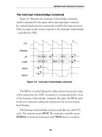
Figure 9-10 shows a solution to that problem utilizing pallet
bridge boards. The host processor resides in the system slot of
Segment B and bridges directly to Segments A and C. Note that
Segment A must have its system slot on the right and that two
different bridge boards are required — one that bridges from right
to left and another that bridges from left to right. In practice, the
same PC board can be used for both forms with different mounting
locations for the connectors.
The same strategy can be implemented with front-loading bridge
modules. At least one vendor (Teknor) currently offers a dual-wide
SBC that incorporates the bridge function.
Figure 9-10: CPCI bridging of three segments.
PCI Bus Demystified
Segment A Segment B Segment C
“Left-hand”
Bridge
“Right-hand”
Bridge
165
Summary
CompactPCI is an industrial implementation of the PCI bus.
It uses a passive backplane and standardized Eurocard mechanics.
The use of low-capacitance connectors allows up to eight PCI slots
per backplane segment.
CompactPCI defines additional signals beyond the basic PCI
protocol. Among the features provided by these extra signals are:
system slot identification, system enumeration and geographical
addressing. Every board requires series termination of the bus signals.
CompactPCI
166
In high-availability, mission-critical environments, it is useful
(in many cases absolutely essential) to be able to swap system
components while the system is running. Attempting to do this in
a system that has not taken Hot Pluggability into account will very
likely result in component damage and system disruption.
Two approaches to Hot Pluggability have been developed. The
PCISIG invented Hot Plug for conventional PCI cards. PICMG
created Hot Swap for CompactPCI. In some ways these approaches
complement each other and in other ways they contrast.
PCI Hot Plug
Hot Plug is defined in the PCI Hot Plug Specification Rev. 1.0
dated October 1997. The primary objective of Hot Plug is “to enable
higher availability of file and application servers by standardizing
key aspects of the process of removing and installing PCI adapter
cards while the system is running”. In an effort to expedite market
acceptance of Hot Plug by making virtually any PCI card Hot Plug-
gable, the specification puts the burden of hardware changes on the
platform vendor. Specifically, the Hot Plug environment requires that
each slot have:
Hot Plug and Hot Swap
C H A P T E R
10
167
■ Power switches such that each board can be independently
powered up and down.
■ Bus isolation switches that electrically isolate the slot from
the bus while a board is being inserted or removed.
■ An independent RST# signal.
■ A way of drawing an operator’s attention to a specific slot,
an “attention indicator”, probably an LED. There may
also be a slot state indicator to show whether the slot is
on or off. The state indicator may be combined with the
attention indicator.
■ Ability to read the PRSNT[1:2]# signals while the board is
isolated from the bus.
■ Ability to read M66EN while the board is isolated from
the bus.
Hot Plug follows what may be termed a “no surprises” strategy.
This means that before inserting or removing a board, the operator
must inform the operating system of his intentions and wait until the
system notifies him that it is OK to proceed.
Hot Plug System Components
Figure 10-1 shows the elements added to a system to support Hot
Plug. These include:
■ Hot Plug Controller. Provides hardware control of the
power and bus isolation switches, individual RST#s and
attention indicators. Monitors PRSNT[1:2]# and M66EN.
■ Hot Plug System Driver. Software interface to the Hot Plug
controller. Implements the Hot Plug primitives described
below.
Hot Plug and Hot Swap
168
■ Hot Plug Service Provides the interface to the user that
allows the user to communicate insertion events to the
system. Also interacts with adapter drivers to quiesce and
activate the driver in response to insertion events.
Hot Plug Insertion
This is the sequence of events that occurs when a board is
inserted into a Hot Plug environment. We start with the assumption
that unoccupied slots are not powered, are isolated from the bus and
that RST# is asserted.
1. The operator inserts the board in the slot.
2. The operator notifies the operating system that the board
has been inserted in a specific slot
3. The Hot Plug Service notifies the Hot Plug System Driver
to turn on the board. In turn, the Hot Plug System Driver
directs the Hot Plug Controller to do the following:
PCI Bus Demystified
Figure 10-1: Hot Plug system components.
Hot-Plug
Controller
Adapter
Driver #1
….
Adapter
Driver #n
Hot-Plug
System
Driver
Hot-Plug
Service
Operating
System
Platform
SW Layers
HW Layers
Adapter Card
#n
Adapter Card
#1
PCI Bus
User
Management
Agent
Attention
Indicator
Bus and
Power Switches
169
■ Power up the slot
■ Deassert RST# and connect the slot to the bus, in
either order.
■ Change the optional slot state indicator to show that
the slot is on.
4. The Hot Plug Service notifies the operating system that
a new board has been inserted. Elements of the operating
system and/or platform-dependent software then proceed
to:
■ Configure the board
■ Load the adapter driver or create a new instance of
the driver
■ Start the driver instance
5. The Hot Plug Service notifies the operator that the board
is ready.
Hot Plug Removal
This is the sequence of events that occurs when a board is
removed from a Hot Plug environment:
1. The operator informs the Hot Plug Service of his desire
to remove a specific board.
2. The Hot Plug Service notifies the operating system to
“quiesce” the corresponding adapter driver instance.
This means that the driver will complete the transaction
currently in process and not accept any more transactions.
When the current transaction is complete, it places the
board in a state that will not generate interrupts or bus
master activity.
Hot Plug and Hot Swap
170
3. The Hot Plug Service notifies the Hot Plug System Driver
to turn off the slot. In turn, the Hot Plug System Driver
directs the Hot Plug Controller to:
■ Assert RST# and isolate the slot from the bus, in either
order.
■ Power down the slot
■ Change the optional slot state indicator to show that
the slot is off.
4. The Hot Plug Service notifies the operator that the slot
is off.
5. The operator removes the board.
Hot Plug Primitives
The Hot Plug Service is normally supplied by the operating
system vendor while the Hot Plug System Driver is normally supplied
by the platform vendor. The Hot Plug Primitives define what infor-
mation must pass between these two elements. The primitives are
defined only in terms of information passed in and information
returned. The actual programming interface is operating system
dependent. The operating system vendor may choose to split each
primitive into multiple operations in the interest of efficiency.
Query Hot Plug System Driver
Parameters passed: None
Parameters returned: Set of logical slot identifiers controlled
by this Hot Plug System Driver
This is the mechanism for each Hot Plug System Driver to report
the set of logical slots that it controls.
PCI Bus Demystified
171
Set Slot Status
Parameters passed: Logical slot identifier
New state {off, on}
New Attention Indicator state {normal,
attention}
Parameters returned: Completion status {successful, wrong
frequency, insufficient power, insufficient
configuration resources, power failure,
general failure}
This request controls the state of a hot plug slot and its associated
Attention Indicator. For purposes of this primitive, a slot has only
two states: on or off. In the on state the slot is powered and con-
nected to the bus. In the off state it is not powered, isolated from the
bus and RST# is asserted.
If the request fails, the Hot Plug System Driver should leave the
slot in the off state unless otherwise indicated. Possible failures
include:
■ Wrong Frequency. A 33 MHz board was plugged into a bus
segment operating at 66 MHz.
■ Insufficient Power. By reading PRSNT[2::1], the Hot Plug
System Driver has determined that there is not enough
power left to turn on this slot.
■ Insufficient Configuration Resources. If the Hot Plug System
Driver is responsible for running the configuration routine,
it may return this error if there are not enough resources
available to configure the board. The slot may be left on
if the operating system can tolerate a partially configured
board.
Hot Plug and Hot Swap
172
■ Power Failure. A power fault, i.e. short, was detected in
the slot.
■ General Failure. Any condition not otherwise covered.
Query Slot Status
Parameters passed: Logical Slot identifier
Parameters returned: Slot state {on, off}
Board power requirement {not present,
low, medium, high}
Board frequency capability {33 MHz,
66 MHz, insufficient power}
Slot frequency {33 MHz, 66 MHz}
This request returns the state of a hot plug slot and any board
that may be plugged in. The Hot Plug System Driver determines a
board’s frequency capability either by reading M66EN or the 66 MHz
CAPABLE bit in the Configuration Header. The driver will return an
indication of insufficient power if it must read the Configuration
Header but is unable to turn on the slot due to insufficient power.
Asynchronous Notification of Slot Status Change
Parameters passed: Logical slot identifier
Parameters returned: None
This primitive is used by the Hot Plug System Driver to notify the
Hot Plug Service of an unsolicited change in the status of a slot such
as a run-time power fault or a new board installed in a previously
empty slot. This is not required for normal Hot Plug insertion and
removal because these operations must follow “orderly procedures.”
However, this primitive is very useful in Hot Swap as we’ll see shortly.
PCI Bus Demystified
173
Expansion ROM
Intel x86 code contained in on-board expansion ROMs is gener-
ally designed to execute at boot time before the operating system is
loaded. Attempting to execute this code at run time when the board
is plugged into a running system may result in serious errors. It is up
to the operating system vendor to specify whether or not expansion
ROM code is executed during a hot insertion. If it is not, the board
vendor must supply an alternate means to accomplish the same
function, perhaps by incorporating it into the device driver.
CompactPCI Hot Swap
Hot Swap is defined by the CompactPCI Hot Swap Specification,
Rev. 1.0 dated August 1998. Hot Swap builds on the architecture
defined by Hot Plug but takes exactly the opposite tack in that the
burden of support is placed on CompactPCI boards rather than the
platform. This makes perfect sense in that the platform is in fact a
passive backplane. The principal objectives of Hot Swap are:
■ Allow “orderly insertion & extraction of boards” without
powering down
■ Provide for system reconfiguration and fault recovery with
no down time
■ Isolate faulty boards so system can continue in presence of
a fault
The other key point that distinguishes Hot Swap from Hot Plug
is the ability of the system to automatically detect an insertion
“event”. This doesn’t mean that a Hot Swap capable operating
system can tolerate surprises, but rather that the impending occur-
rence of an insertion event can be communicated to the operating
system automatically.
Hot Plug and Hot Swap
174
Hot Swap Processes
Hot Swap can be described in terms of three processes. These
processes can be described further as a procession of states. Each
succeeding state is dependent on the success of the preceding state.
The processes are described below in terms of board insertion where
the order is:
1. Physical Connection
2. Hardware Connection
3. Software Connection
Board extraction operates in the reverse order:
1. Software Disconnection
2. Hardware Disconnection
3. Physical Extraction
Physical Connection
This is the process of actually inserting or removing the board.
This process is embodied in the notion of “pin staging” or different
pin lengths that are intended to make physical connection at differ-
ent times. The first physical element to make contact as a board is
inserted is the electrostatic card guide. Its purpose is to discharge any
static accumulation that may have built up on the inserted board.
Nevertheless, the specification cautions that “Normal ESD protec-
tion should be used when hot swapping boards.”
The longest pins — the first to make contact — are called the
“Early Voltages”. These comprise two each +5V and +3.3V, the
VIO pins and several grounds. The objective is to provide power for
the PCI interface independent of the “backend,” application logic.
At this stage, all of the PCI bus lines are precharged to approximately
one volt to minimize the capacitive effects of attaching the lines to
PCI Bus Demystified
175
the active bus. Note that there is no guarantee as to what order these
pins make contact. The only guarantee is that they will make contact
before the next set of pins.
The medium length pins — the next to make contact — constitute
all of the PCI bus signals. By the time they make contact they have
been charged up to a voltage level that will not disturb operations on
the bus.
Finally, the board contacts the two short pins, BDSEL# and
IDSEL. The board pulls BDSEL# high with a pullup resistor. On the
backplane this signal is either grounded or controlled by a High
Availability platform.
The primary obligation of a Hot Swap board is to make a dis-
tinction between Early Power and Back End Power. Early Power is
provided by long pins and is intended to power the PCI interface
silicon so as to precharge all PCI bus lines to about 1 volt. Early
power is limited to two amps.
Back end power is provided by all those power pins that are not
long but rather medium. This is what provides power to the appli-
cation logic after the PCI interface has stabilized. Even though the
back end power pins are medium length, the board itself must control
switching of back end power based on the assertion of BDSEL#.
Hot Plug and Hot Swap
Long Pins Two each: +5 volts, +3.3 volts, Vio
(first to engage) Six Gnd
Short Pins BDSEL#, IDSEL
(last to engage)
Medium Pins Everything else
Table 10-1: Pin staging.
176
Hardware Connection
This is the process of getting the board ready to configure. The
board is connected to the PCI bus and the backend application logic
is powered up. In the Basic and Full Hot Swap models this process
happens automatically by virtue of contacting the BDSEL# pin.
In the High Availability model BDSEL# is controlled by software
through the Hot Swap Controller.
Software Connection
The Software Connection process begins with the deassertion
of RST#. First, system software assigns resources to the board and
initializes the board’s Configuration Header. Next the device driver
and other supporting software are loaded and/or instantiated. The
board is now ready to be used.
Hot Swap Models
Hot Swap defines three levels of Hot Swap functionality as shown
in Table 10-2. These are differentiated mainly in how the hardware
and software connection processes are carried out. Basic Hot Swap
is the simplest in terms of its impact on both boards and backplanes
and, not surprisingly, has the least capability. The Basic Model
operates much like Hot Plug in that the operator must interact with
PCI Bus Demystified
Table 10-2: Hot Swap models.
System Type Hardware Connection Software Connection
Basic Hot Swap Automatic in HW Manually by Operator
Full Hot Swap Automatic in HW
Controller (Automatic)
by Software
High Availability Controlled by SW
Controller (Automatic)
by Software
177
the system to effect software connection and disconnection and
the functions must be performed in the correct sequence for proper
system operation.
Full Hot Swap provides facilities that automatically notify the
system software that a board is either being plugged in or removed.
This allows the software connection process to be automated.
High Availability adds software control of the hardware connec-
tion process in order to detect and, hopefully, isolate faulty boards.
Each model builds on the facilities of the preceding simpler one.
The three models lead to several definitions of both platforms
and boards as shown in Figure 10-2. The Hot Swap architecture is
designed to allow all combinations of platforms and boards to inter-
operate. The system model is determined by the features of the lowest
common denominator.
Platforms come in three flavors:
■ Non-Hot Swap platforms lack any or all of the elements
required to support Hot Swap.
Hot Plug and Hot Swap
Figure 10-2: Hot Swap interoperability.
Compact PCI Bus
Compact PCI Bus
Compact PCI Bus
HW
Control
HW Conn
Control
Conventional Compact PCI HW
Conventional Compact PCI HW
Conventional Compact PCI HW
Hardware Connection Layer
Hardware Connection Layer
SW Conn Control
Board
Non Hot
Swap
Basic
Hot Swap
Full Hot
Swap
Platform
Non Hot
Swap
Hot Swap
High
Availability
178
■ Hot Swap platforms contain all the required Hot Swap elements.
■ High Availability (HA) platforms contain the required Hot Swap
elements plus a platform-specific implementation for Hardware
Connection Control
Likewise, boards come in three flavors:
■ Non-Hot Swap boards don’t have a Hardware Connection Layer.
■ Basic Hot Swap boards have the Hardware Connection Layer.
■ Full Hot Swap boards add the Software Connection Control
resources.
PCI Bus Demystified
Table 10-3: System configurations.
Platform Type Board Type System
Non-Hot Swap
Non-Hot Swap Basic Hot Swap Conventional Compact PCI
Full Hot Swap
Non-Hot Swap Conventional CompactPCI
Hot Swap Basic Hot Swap Basic Hot Swap System
Full Hot Swap Full Hot Swap System
Non-Hot Swap Conventional CompactPCI
High Availability Basic Hot Swap
Full Hot
Swap
High Availability System
The various combinations of platforms and boards lead to the set
of system configurations shown in Table 10-3. The Hot Swap specifi-
cation layers on top of the basic Compact PCI Specification, providing
backward compatibility and allowing Hot Swap to operate in a con-
ventional platform. This configuration does not support Hot Swap.
179
A Hot Swap platform can have a mixture of Hot Swap and
Non-Hot Swap boards. The Non-Hot Swap elements are of course
not Hot Swappable but otherwise function normally. The Hot Swap
boards are swappable. Note that HA functionality is a function of the
platform and not the boards.
The specification cautions that mixing Basic and Full Hot Swap
boards can create an environment that “could be confusing to the
operator. If some boards configure automatically, and some require
operator intervention, the operator may incorrectly insert (or extract)
a board.”
Figure 10-3 shows the overall architectural model encompassing
both hardware and software. Note the Hot Plug Service and Hot Plug
System Driver. These are essentially the same elements defined by PCI
Hot Plug.
Hot Plug and Hot Swap
Figure 10-3: Hot Swap system architecture.
Hardware Connection Layer
Conventional Compact PCI HW
Compact PCI Bus
Device
Driver
Device
Driver
Device
Driver
SW Connection
Control HAL
Hot Plug Service
Operating System
SW Connection Control
Board
Hardware
Platform
Hardware
Hardware
Abstraction
Drivers
API
Software
Layers
HW Connection Control
HA System Driver
HW Connection
Control HAL
Hot Plug System Driver
HA Service
Basic Hot Swap
Full Hot Swap
High Availability
180
Resources for Full Hot Swap
The Software Connection process for Full Hot Swap requires
several additional resources on both the board and the platform.
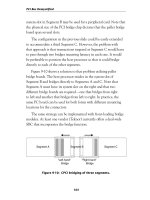
Handle Switch and Status LED
A full Hot Swap board has a switch activated by the lower
ejector handle as shown in Figure 10-4. On insertion the switch
changes state when the board is fully seated and the ejector handle
is locked. On extraction, the switch changes state as soon as the
handle is unlocked and before any movement of the board. The
change in state of the switch is used to assert the ENUM# signal
as described below.
System software lights the LED when it is safe to remove the
board. This LED is blue and is also located near the lower ejector
handle.
ENUM# Signal
The ENUM# signal is asserted to indicate a board insertion or
extraction event. This tells the system software to enumerate the
bus to determine the source of the event and what type of event
(insertion or extraction) it is. ENUM# is controlled by the ejector
handle switch. On insertion, ENUM# is asserted when the handle is
locked after the board is fully inserted. On extraction, it is asserted
when the handle is unlocked and before any movement of the board.
In response to ENUM#, the system software reads the Hot Swap
Control/Status Register (CSR) to determine which board caused
the enumeration event and what kind of event it is. For an insertion
event the system activates the software connection process for the
inserted board. For an extraction event the system activates the
PCI Bus Demystified
181
software disconnection process. When that process is complete,
i.e. the board is “quiesced,” the system will illuminate the Status
LED to inform the operator that it is safe to remove the board. The
operator must not remove the board until the Status LED is lit.
The system may poll ENUM# but it is highly recommended that
response to ENUM# be interrupt driven.
Hot Plug and Hot Swap
Figure 10-4: Hot Swap board with handle switch and status LED.
16.63
LED PLACEMENT
8.00
15.00
3.80
3.06
3.50
(2.50) COMPONENT
KEEP OUT AREA
(2.50) COMPONENT
KEEP OUT AREA
6.86
11.5
SPACE RESERVED FOR
CONNECTOR, CONNECTION,
OR SWITCH
FRONT PANEL
FRONT VIEW
FRONT PANEL
SIDE VIEW
182
Hot Swap Control/Status Register
Figure 10-5 shows the Hot Swap Control/Status Register
(HS_CSR). Two control and status bits are used by the software to
identify the nature of an ENUM event. The INS bit indicates that
the board has been inserted. The EXT bit means the board is about to
be extracted. The assertion of either bit causes ENUM# to be asserted.
When the Hot Swap driver identifies the event it writes a one to the
appropriate bit (INS or EXT) to clear it. LOO (LED On/Off) controls
the Status LED and EIM masks the assertion of ENUM#.
PCI Bus Demystified
Figure 10-5: Hot Swap control/status register.
Figure 10-6: HS_CSR capabilities list entry.
EIM
LOOEXTINS
ENUM# Mask
1 = mask
0 = enable
LED On/Off
1 = on
0 = off
ENUM# status = extraction
ENUM# status = insertion
07
31
24 23 16 15 8 7 0
Reserved
HS_CSR Next Item 6
Capability ID
(6 = Hot Swap CSR)
The preferred implementation of the HS_CSR, supported by
“Hot Swap friendly” silicon, is as an Extended Capability using the
Extended Capability Pointer in the Configuration Header. Figure
10-6 shows the Capability List entry.
183
Hot Plug and Hot Swap
Resources for High Availability
The additional features of the High Availability model are
supported by a set of three radial signals that connect each slot to
a Hot Swap Controller (HSC). The connection to the HSC, indeed
the very location of the HSC, is considered outside the scope of the
specification, that is it is platform-dependent. The three radial signals
are: BD_SEL#, HEALTHY# and RST#.
BD_SEL# is used to control power to the back end logic on the
board. It is pulled up to Vio with a 1.2 K resistor on the board. Back
end power is applied when BD_SEL# is asserted.
In a platform without hardware connection control, BD_SEL# is
simply tied to ground (see Figure 10-7). In fact, the pin is called out
as GND in earlier revisions of the Compact PCI Specification. In this
case back end power is turned on as soon as the short BD_SEL# pin
makes contact.
In a HA platform the HSC pulls BD_SEL# down with a relatively
high value resistor. So when no board is inserted, the HSC sees
BD_SEL# as low. Upon insertion, the board’s pullup overcomes the
weak pulldown of the HSC and drives BD_SEL# high or unasserted
Figure 10-7: Handling of the BD_SEL# signal.
Platform / Board Platform / Board
Hardware Connection Control
No Hardware
Connection Control
Power
Circuitry
Power
Circuitry
ON
BD_SEL#
BD_SEL#
V/O
ON
V/O
HSC
PWR ON