Mechanical Engineer´s Handbook P53 ppt
Bạn đang xem bản rút gọn của tài liệu. Xem và tải ngay bản đầy đủ của tài liệu tại đây (1.01 MB, 21 trang )
38.1
INTRODUCTION
Material
handling
is
defined
by the
Materials
Handling
Institute
(MHI)
as the
movement,
storage,
control,
and
protection
of
materials
and
products
throughout
the
process
of
their
manufacture,
dis-
tribution,
consumption,
and
disposal.
The five
commonly
recognized
aspects
of
material
handling
are:
Mechanical Engineers'
Handbook,
2nd
ed.,
Edited
by
Myer
Kutz.
ISBN
0-471-13007-9
©
1998
John Wiley
&
Sons, Inc.
CHAPTER
38
MATERIAL
HANDLING
William
E.
Biles
Mickey
R.
Wilhelm
Department
of
Industrial Engineering
University
of
Louisville
Louisville,
Kentucky
Magd
E.
Zohdi
Department
of
Industrial
and
Manufacturing
Engineering
Louisiana State University
Baton
Rouge,
Louisiana
38.1
INTRODUCTION
1205
38.2
BULK MATERIAL HANDLING 1206
38.2.1
Conveying
of
Bulk
Solids
1206
38.2.2
Screw Conveyors
1207
38.2.3
Belt
Conveyors
1207
38.2.4
Bucket
Elevators
1208
38.2.5
Vibrating
or
Oscillating
Conveyors
1208
38.2.6
Continuous-Flow
Conveyors
1208
38.2.7
Pneumatic Conveyors
1208
38.3
BULK MATERIALS STORAGE 1212
38.3.1
Storage
Piles
1212
38.3.2
Storage
Bins,
Silos,
and
Hoppers
1212
38.3.3
Flow-Assisting
Devices
and
Feeders
1214
38.3.4 Packaging
of
Bulk
Materials
1214
38.3.5
Transportation
of
Bulk
Materials
1218
38.4
UNIT
MATERIAL HANDLING 1219
38.4.1
Introduction
1219
38.4.2
Analysis
of
Systems
for
Material
Handling
1220
38.4.3
Identifying
and
Defining
the
Problem
1220
38.4.4
Collecting
Data
1220
38.4.5
Unitizing
Loads
1223
38.5
MATERIAL-HANDLING
EQUIPMENT
CONSIDERATIONS
AND
EXAMPLES
1225
38.5.1
Developing
the
Plan
1225
38.5.2 Conveyors
1226
38.5.3
Hoists,
Cranes
and
Monorails
1233
38.5.4
Industrial
Trucks
1234
38.5.5 Automated Guided
Vehicle
Systems
1234
38.5.6 Automated
Storage
and
Retrieval
Systems
1234
38.5.7 Carousel Systems
1236
38.5.8
Shelving,
Bin, Drawer,
and
Rack
Storage
1238
38.6
IMPLEMENTING
THE
SOLUTION
1239
1.
Motion.
Parts, materials,
and finished
products
that
must
be
moved
from
one
location
to
another should
be
moved
in an
efficient
manner
and at
minimum
cost.
2.
Time.
Materials
must
be
where
they
are
needed
at the
moment
they
are
needed.
3.
Place. Materials
must
be in the
proper location
and
positioned
for
use.
4.
Quantity.
The
rate
of
demand
varies
between
the
steps
of
processing operations. Materials
must
be
continually delivered
to, or
removed
from,
operations
in the
correct weights,
volumes,
or
numbers
of
items required.
5.
Space.
Storage space,
and its
efficient
utilization,
is a key
factor
in the
overall cost
of an
operation
or
process.
The
science
and
engineering
of
material handling
is
generally
classified
into
two
categories,
depending
upon
the
form
of the
material handled.
Bulk
solids handling involves
the
movement
and
storage
of
solids
that
are flowable,
such
as fine,
free-flowing materials (e.g.,
wheat
flour or
sand),
pelletized
materials (e.g.,
soybeans
or
soap
flakes), or
lumpy
materials (e.g., coal
or
wood
bark).
Unit
handling refers
to the
movement
and
storage
of
items
that
have
been
formed
into unit loads.
A
unit
load
is a
single item,
a
number
of
items,
or
bulk material
that
is
arranged
or
restrained
so
that
the
load
can be
stored, picked
up, and
moved
between
two
locations
as a
single
mass.
The
handling
of
liquids
and
gases
is
usually considered
to be in the
domain
of fluid
mechanics,
whereas
the
movement
and
storage
of
containers
of
liquid
or
gaseous
material properly
comes
within
the
domain
of
unit
material handling.
38.2
BULK
MATERIAL
HANDLING
The
handling
of
bulk solids involves four
main
areas:
(1)
conveying,
(2)
storage,
(3)
packaging,
and
(4)
transportation.
38.2.1
Conveying
of
Bulk
Solids
The
selection
of the
proper
equipment
for
conveying
bulk solids
depends
on a
number
of
interrelated
factors.
First,
alternative types
of
conveyors
must
be
evaluated
and the
correct
model
and
size
must
be
chosen.
Because
standardized
equipment
designs
and
complete
engineering data
are
available
for
many
types
of
conveyors,
their
performance
can be
accurately predicted
when
they
are
used with
materials having
well-known
conveying
characteristics.
Some
of the
primary
factors involved
in
conveyor
equipment
selection
are as
follows:
1.
Capacity requirement.
The
rate
at
which
material
must
be
transported (e.g., tons
per
hour).
For
instance,
belt
conveyors
can be
manufactured
in
relatively large sizes, operate
at
high
speeds,
and
deliver large weights
and
volumes
of
material
economically.
On the
other
hand,
screw
conveyors
can
become
very
cumbersome
in
large sizes,
and
cannot
be
operated
at
high
speeds without severe abrasion
problems.
2.
Length
of
travel.
The
distance material
must
be
moved
from
origin
to
destination.
For
instance,
belt
conveyors
can
span miles,
whereas
pneumatic
and
vibrating
conveyors
are
limited
to
hundreds
of
feet.
3.
Lift.
The
vertical
distance material
must
be
transported. Vertical bucket elevators
are
com-
monly
applied
in
those cases
in
which
the
angle
of
inclination exceeds 30°.
4.
Material characteristics.
The
chemical
and
physical properties
of the
bulk solids
to be
transported, particularly
flowability.
5.
Processing
requirements.
The
treatment material incurs during transport, such
as
heating,
mixing,
and
drying.
6.
Life expectancy.
The
period
of
performance
before
equipment
must
be
replaced; typically,
the
economic
life
of the
equipment.
7.
Comparative
costs.
The
installed
first
cost
and
annual operating costs
of
competing
conveyor
systems
must
be
evaluated
in
order
to
select
the
most
cost-effective configuration.
Table
38.1
lists
various types
of
conveyor
equipment
for
certain
common
industrial functions.
Table
38.2 provides information
on the
various types
of
conveyor
equipment
used with materials having
certain
characteristics.
The
choice
of the
conveyor
itself
is not the
only task involved
in
selecting
a
conveyor
system.
Conveyor
drives,
motors,
and
auxiliary
equipment
must
also
be
chosen.
Conveyor
drives
comprise
from
10%-30%
of the
total
cost
of the
conveyor
system.
Fixed-speed drives
and
adjustable speed
drives
are
available,
depending
on
whether
changes
in
conveyor
speed
are
needed
during
the
course
of
normal
operation.
Motors
for
conveyor
drives
are
generally three-phase,
60-cycle,
220-V
units;
220/440-V
units;
550-V
units;
or
four-wire,
208-V
units.
Also
available
are
240-V
and
480-V
ratings.
Auxiliary
equipment
includes such items
as
braking
or
arresting devices
on
vertical
elevators
to
prevent reversal
of
travel,
torque-limiting devices
or
electrical
controls
to
limit
power
to the
drive
motor,
and
cleaners
on
belt
conveyors.
38.2.2
Screw
Conveyors
A
screw
conveyor
consists
of a
helical shaft
mount
within
a
pipe
or
trough.
Power
may be
transmitted
through
the
helix,
or in the
case
of a
fully
enclosed pipe
conveyor
through
the
pipe
itself.
Material
is
forced
through
the
channel
formed
between
the
helix
and the
pipe
or
trough.
Screw
conveyors
are
generally limited
to
rates
of flow of
about
10,000
ft3/hr.
Figure
38.1
shows
a
chute-fed
screw
con-
veyor,
one of
several types
in
common
use. Table 38.3 gives capacities
and
loading conditions
for
screw
conveyors
on the
basis
of
material classifications.
38.2.3
Belt
Conveyors
Belt
conveyors
are
widely used
in
industry.
They
can
traverse distances
up to
several miles
at
speeds
up to
1000
ft/min
and can
handle thousands
of
tons
of
material
per
hour. Belt conveyors
are
generally
placed horizontally
or at
slopes ranging
from
10°-20°,
with
a
maximum
incline
of
30°. Direction
changes
can
occur
readily
in the
vertical
plane
of the
belt
path,
but
horizontal direction changes
must
be
managed
through such devices
as
connecting chutes
and
slides
between
different sections
of
belt
conveyor.
Belt-conveyor design
depends
largely
on the
nature
of the
material
to be
handled. Particle-size
distribution
and
chemical
composition
of the
material dictate selection
of the
width
of the
belt
and
the
type
of
belt.
For
instance, oily substances generally rule
out the use of
natural rubber
belts.
Conveyor-belt
capacity
requirements
are
based
on
peak
load rather than average load. Operating
conditions
that
affect belt-conveyor design include climate, surroundings,
and
period
of
continuous
service.
For
instance,
continuous
service operation will require higher-quality
components
than will
intermittent
service,
which
allows
more
frequent
maintenance.
Belt width
and
speed
depend
on the
bulk
density
of the
material
and
lump
size.
The
horsepower
to
drive
the
belt
is a
function
of the
following factors:
1.
Power
to
drive
an
empty
belt
Table
38.2
Material
Characteristics
and
Feeder
Type
Table
38.1
Types
of
Conveyor
Equipment
and
Their
Functions
Function
Conveying
materials horizontally
Conveying
materials
up or
down
an
incline
Elevating materials
Handling
materials over
a
combination
horizontal
and
vertical path
Distributing materials
to or
collecting materials
from
bins,
bunkers,
etc.
Removing
materials
from
railcars,
trucks, etc.
Conveyor
Type
Apron,
belt,
continuous
flow,
drag
flight,
screw,
vibrating,
bucket, pivoted bucket,
air
Apron,
belt,
continuous
flow, flight,
screw,
skip
hoist,
air
Bucket
elevator, continuous
flow,
skip hoist,
air
Continuous
flow,
gravity-discharge bucket,
pivoted bucket,
air
Belt,
flight,
screw, continuous
flow,
gravity-
discharge bucket, pivoted bucket,
air
Car
dumper,
grain-car unloader,
car
shaker,
power
shovel,
air
Material
Characteristics
Fine, free-flowing materials
Nonabrasive
and
granular materials, materials
with
some
lumps
Materials
difficult
to
handle
because
of
being
hot,
abrasive,
lumpy,
or
stringy
Heavy,
lumpy,
or
abrasive materials similar
to
pit-run
stone
and ore
Feeder
Type
Bar flight,
belt,
oscillating
or
vibrating, rotary
vane,
screw
Apron,
bar flight,
belt,
oscillating
or
vibrating,
reciprocating, rotary plate,
screw
Apron,
bar flight,
belt,
oscillating
or
vibrating,
reciprocating
Apron,
oscillating
or
vibrating, reciprocating
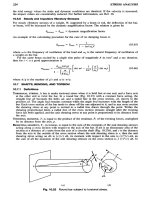
Fig.
38.1
Chute-fed
screw
conveyor.
2.
Power
to
move
the
load against
the
friction
of the
rotating parts
3.
Power
to
elevate
and
lower
the
load
4.
Power
to
overcome
inertia
in
placing material
in
motion
5.
Power
to
operate
a
belt-driven tripper
Table
38.4
provides
typical
data
for
estimating belt-conveyor
and
design requirements. Figure
38.2
illustrates
a
typical belt-conveyor loading
arrangement.
38.2.4
Bucket
Elevators
Bucket
elevators
are
used
for
vertical
transport
of
bulk solid materials.
They
are
available
in a
wide
range
of
capacities
and may
operate
in the
open
or
totally
enclosed.
They
tend
to be
acquired
in
highly standardized units, although specifically engineered
equipment
can be
obtained
for use
with
special
materials, unusual operating conditions,
or
high capacities. Figure 38.3
shows
a
common
type
of
bucket
elevator,
the
spaced-bucket centrifugal-discharge elevator.
Other
types include spaced-
bucket positive-discharge elevators,
V-bucket
elevators, continuous-bucket elevators,
and
super-
capacity
continuous-bucket elevators.
The
latter
handle high tonnages
and are
usually operated
at an
incline
to
improve
loading
and
discharge conditions.
Bucket
elevator
horsepower
requirements
can be
calculated
for
space-bucket elevators
by
multi-
plying
the
desired capacity (tons
per
hour)
by the
lift
and
dividing
by
500.
Table
38.5
gives bucket
elevator
specifications
for
spaced-bucket, centrifugal-discharge elevators.
38.2.5
Vibrating
or
Oscillating
Conveyors
Vibrating
conveyors
are
usually directional-throw devices
that
consist
of a
spring-supported
horizontal
pan or
trough vibrated
by an
attached
arm or
rotating weight.
The
motion
imparted
to the
material
particles
abruptly tosses
them
upward
and
forward
so
that
the
material
travels
in the
desired direction.
The
conveyor
returns
to a
reference position,
which
gives
rise to the
term oscillating conveyor.
The
capacity
of the
vibrating
conveyor
is
determined
by the
magnitude
and
frequency
of
trough displace-
ment,
angle
of
throw,
and
slope
of the
trough,
and the
ability
of the
material
to
receive
and
transmit
through
its
mass
the
directional
"throw"
of the
trough. Classifications
of
vibrating
conveyors
include
(1)
mechanical,
(2)
electrical,
and (3)
pneumatic
and
hydraulic
vibrating
conveyors.
Capacities
of
vibrating
conveyors
are
very broad, ranging
from
a few
ounces
or
grams
for
laboratory-scale equip-
ment
to
thousands
of
tons
for
heavy
industrial applications. Figure
38.4
depicts
a
leaf-spring
me-
chanical vibrating
conveyor,
and
provides
a
selection chart
for
this
conveyor.
38.2.6
Continuous-Flow
Conveyors
The
continuous-flow
conveyor
is a
totally
enclosed unit
that
operates
on the
principle
of
pulling
a
surface transversely through
a
mass
of
bulk solids material, such
that
it
pulls along with
it a
cross
section
of
material
that
is
greater than
the
surface
of the
material
itself.
Figure
38.5
illustrates
a
typical
configuration
for a
continuous-flow
conveyor.
Three
common
types
of
continuous
flow
con-
veyors
are (1)
closed-belt
conveyors,
(2)
flight
conveyors,
and (3)
apron
conveyors.
These
conveyors
employ
a
chain-supported transport device,
which
drags through
a
totally
enclosed boxlike tunnel.
38.2.7
Pneumatic
Conveyors
Pneumatic
conveyors operate
on the
principle
of
transporting bulk solids
suspended
in a
stream
of
air
over
vertical
and
horizontal distances ranging
from
a few
inches
or
centimeters
to
hundreds
of
feet
or
meters. Materials
in the
form
of fine
powders
are
especially suited
to
this
means
of
conveyance,
although
particle
sizes
up to a
centimeter
in
diameter
can be
effectively transported pneumatically.
Materials with bulk densities
from
one to
more
than
100
lb/ft3
can be
transported through
pneumatic
conveyors.
The
capacity
of a
pneumatic
conveying
system
depends
on
such factors
as the
bulk density
of
the
product, energy within
the
conveying
system,
and the
length
and
diameter
of the
conveyor.
Table
38.3
Capacity
and
Loading
Conditions
for
Screw
Conveyors
Max.
Hp.
Capacity
at
Speed
Listed
75ft
Max.
Length
Hp at
Motor
30 ft 45 ft 60 ft
Max.
Max. Max.
Length Length Length
15ft
Max.
Length
Feed
Section
Diam.
(in.)
Max.
Torque
Capacity
(in lb)
Speed
(rpm)
Max.
Size
Lumps
Lumps
10%
All
Lumps
or
Lumps
20-25%
Less
Hanger
Centers
(ft)
Diam.
of
Shafts
(in.)
Diam.
of
Pipe
(in.)
Diam.
of
Flights
(in.)
Capacity
tons/hr
ft3/hr
4.8
6.6
9.6
5.4
11.7
7.2
15.6
9.0
19.5
11.7
14.3
16.9
13.0
2.11
3.75
4.93
4.93
4.93
5.63
5.63
6.55
6.55
6.55
7.50
8.75
10.00
1.69
3.00
3.94
3.94
3.94
4.87
4.87
5.63
5.63
5.63
6.75
7.00
8.00
1.27
2.25
3.38
3.38
3.38
3.94
3.94
4.93
4.93
4.93
5.05
5.90
6.75
0.85
1.69
2.25
2.25
2.25
3.00
3.00
3.75
3.75
3.75
3.94
4.58
4.50
0.43
0.85
1.27
1.27
1.27
1.69
1.69
2.12
2.12
2.12
2.25
2.62
3.00
6
9
9
10
10
10
12
12
12
14
7,600
7,600
7,600
7,600
16,400
7,600
16,400
7,600
16,400
16,400
16,400
16,400
16,400
40
55
80
45
60
75
45
55
65
50
21/4
2V2
2l/2
3
3
3
3l/2
3l/2
3V2
4
P/2
IV2
ll/2
2
2
2
2l/2
2l/2
2V2
3
3/4
3/4
3/4
1
1
1
VA
ll/4
ll/4
ll/2
10
10
10
12
12
12
12
12
12
2
2
2
2
3
2
3
2
3
3
3
3
3
2l/2
2l/2
2l/2
2l/2
3l/2
2l/2
3l/2
2l/2
3l/2
3l/2
3l/2
3l/2
3l/2
9
10
10
12
12
12
12
14
14
14
16
5
200
10
400
15
600
20
800
25
1000
30
1200
35
1400
40
1600
Table
38.4 Data
for
Estimating Belt
Conveyor Design Requirements
Add
hp for
Tripper
1
00
Ib/ft3
Material
hp hp
Capacity
10-ft
100-ft
(tons/hr)
Lift
Centers
50
Ib/ft3
Material
hp
hp
Capacity
10-ft
100-ft
(tons/hr)
Lift
Centers
Belt
Speed
(ft/min)
Max.
Size
Lump
(in.)
Sized Unsized
Material
Material
80% Not
Over
Under
20%
Belt
Plies
Min.
Max.
Belt
Speed
Normal
Max.
Operating
Advisable
Speed Speed
(ft/min)
(ft/min)
Cross-
Sectional
Area
of
Load
(ft2)
Belt
Width
(in.)
1.00
1.25
1.50
1.60
1.75
2.50
3.53
4.79
6.42
10.56
0.44
0.88
1.32
0.56
1.12
1.68
0.7
1.76
2.42
0.84
2.06
2.9
1.02
3.04
4.04
1.5
4.5
6.74
1.59
6.36
9.52
2.28
9.12
13.68
3.04
12.14
18.2
3.94
17.7
23.6
4.98
22.4
29.9
0.34
0.68
1.04
0.46
0.90
1.36
0.58
1.42
2.00
0.70
1.72
2.44
1.02
3.06
4.08
1.60
4.80
7.20
2.44
9.74
14.6
3.50
14.0
23.2
4.66
18.7
28.0
6.04
27.2
36.2
7.64
34.4
45.8
32
64
96
44
88
132
54
134
190
66
164
230
98
294
392
158
474
710
230
920
1380
330
1320
1980
440
1760
2640
570
2564
3420
720
3240
4320
0.22
0.44
0.66
0.28
0.56
0.84
0.35
0.88
1.21
0.42
1.03
1.45
0.51
1.52
2.02
0.75
2.25
3.37
0.80
3.18
4.76
1.14
4.56
6.84
1.52
6.07
9.10
1.97
8.85
11.82
2.49
11.20
14.95
0.17
0.34
0.52
0.23
0.45
0.68
0.29
0.71
1.00
0.35
0.86
1.22
0.51
1.53
2.04
0.80
2.40
3.60
1.22
4.87
7.30
1.75
7.00
11.6
2.33
9.35
14.0
3.02
13.6
18.1
3.82
17.2
22.9
16
32
48
22
44
66
27
67
95
33
82
115
49
147
196
79
237
355
115
460
690
165
660
990
220
880
1320
285
1282
1710
360
1620
2160
100
200
300
100
200
300
100
250
350
100
250
350
100
300
400
100
300
450
100
400
600
100
400
600
100
400
600
100
450
600
100
450
600
3
4
5
6
8
12
15
18
21
24
28
2
2V2
3
3l/2
4l/2
1
8
10
12
14
16
3
5
3
5
4 6
4 6
4 7
4 8
4 9
4 10
4 12
6 12
6 13
300
300
350
350
400
450
600
600
600
600
600
200
200
250
250
300
300
400
400
400
450
450
0.11
0.14
0.18
0.22
0.33
0.53
0.78
1.09
1.46
1.90
2.40
14
16
18
20
24
30
36
42
48
54
60
Fig.
38.2
A
typical belt
conveyor
loading
arrangement.
Fig.
38.3
Bucket
elevators.
There
are
four basic types
of
pneumatic
conveyor
systems:
(1)
pressure,
(2)
vacuum,
(3)
combi-
nation pressure
and
vacuum,
and (4)
fluidizing.
In
pressure systems,
the
bulk solids material
is
charged
into
an air
stream operated
at
higher-than-atmospheric
pressures, such
that
the
velocity
of the air
stream maintains
the
solid particles
in
suspension
until
it
reaches
the
separating vessel, usually
an
air
filter
or
cyclone separator.
Vacuum
systems
operate
in
much
the
same
way, except
that
the
pressure
of the
system
is
kept
lower
than atmospheric pressure.
Pressure-vacuum
systems
combine
the
best
features
of
these
two
techniques, with
a
separator
and a
positive-displacement
blower
placed
between
the
vacuum
"charge"
side
of the
system
and the
pressure
"discharge"
side.
One of the
most
common
applications
of
pressure-vacuum
systems
is
with
the
combined
bulk vehicle (e.g.,
hopper
car)
un-
loading
and
transporting
to
bulk storage. Fluidizing
systems
operate
on the
principle
of
passing
air
through
a
porous
membrane,
which
forms
the
bottom
of the
conveyor,
thus giving
finely
divided,
non-free-flowing bulk solids
the
characteristics
of
free-flowing material. This technique,
commonly
employed
in
transporting bulk solids over short distances (e.g.,
from
a
storage
bin to the
charge point
to
a
pneumatic
conveyor),
has the
advantage
of
reducing
the
volume
of
conveying
air
needed,
thereby
reducing
power
requirements. Figure
38.6
illustrates
these four types
of
pneumatic
conveyor
systems.
38.3 BULK MATERIALS
STORAGE
38.3.1
Storage
Piles
Open-yard
storage
is a
commonplace
approach
to the
storage
of
bulk solids. Belt
conveyors
are
most
often
used
to
transport
to and
from
such
a
storage area.
Cranes,
front-end loaders,
and
draglines
are
commonly
used
at the
storage
site.
Enclosed
storage piles
are
employed
where
the
bulk solids
ma-
terials
can
erode
or
dissolve
in
rainwater,
as in the
case
of
salt
for use on icy
roads.
The
necessary
equipment
for one
such application,
the
circular storage
facility,
is (1)
feed
conveyor,
(2)
central
support
column,
(3)
stacker,
(4)
reclaimer,
(5)
reclaim
conveyor,
and (6) the
building
or
dome
cover.
38.3.2
Storage
Bins,
Silos,
and
Hoppers
A
typical storage vessel
for
bulk solids materials consists
of two
components—a
bin and a
hopper.
The bin is the
upper section
of the
vessel
and has
vertical
sides.
The
hopper
is the
lower
part
of the
vessel,
connecting
the bin and the
outlet,
and
must
have
at
least
one
sloping side.
The
hopper
serves
as
the
means
by
which
the
stored material
flows to the
outlet channel.
Flow
is
induced
by
opening
the
outlet
port
and
using
a
feeder device
to
move
the
material,
which
drops through
the
outlet port.
If
all
material stored
in the bin
moves
whenever
material
is
removed
from
the
outlet port,
mass
flow
is
said
to
prevail.
However,
if
only
a
portion
of the
material
moves,
the
condition
is
called
funnel
flow.
Figure
38.7
illustrates
these
two
conditions.
Many
flow
problems
in
storage bins
can be
reduced
by
taking
the
physical characteristics
of the
bulk material into account. Particle size,
moisture
content, temperature, age,
and oil
content
of the
Belt
Width
(in.)
Diameter
of
Pulleys (in.)
Head
Tail
Shaft
Diameter
(in.)
Head
Tail
Bucket
Spacing
(in.)
Additional
Horsepower*3
per
Foot
for
Intermediate
Lengths
Horsepower"
Required
at
Head
Shaft
rpm
Head
Shaft
Bucket
Speed
(ft/min)
Size
Lumps
Handled
(in.)c
Capacity
(tons/hr)
Material
Weighing
100lb/ftb
Elevator
Centers
(ft)
Size
of
Bucket
(in.)a
7
7
7
9
9
9
11
11
11
13
13
13
15
15
15
18
18
18
20 14
20 14
20 14
20 14
24 14
24 14
20 16
24 16
24 16
24 18
30 18
30 18
30 18
30 18
30 18
30
20
30
20
30
20
115/16
1U/16
115/16
1U/16
115/16
1U/16
115/16
1U/16
115/16
1U/16
27/16
1U/16
115/16
115/16
27/16
115/16
215/16
115/16
27/16
115/16
215/16
115/16
37/16
27/16
215/16
27/16
37/16
27/16
37/16
27/16
215/16
27/16
37/16
27/16
315/16
27/16
12
12
12
14
14
14
16
16
16
18
18
18
18
18
18
18
18
18
0.02
0.02
0.02
0.04
0.05
0.05
0.063
0.07
0.07
0.1
0.115
0.115
0.14
0.14
0.14
0.165
0.165
0.165
1.0
1.6
2.1
1.6
3.5
4.8
3.0
5.2
7.2
4.7
8.9
11.7
7.3
11.0
14.3
8.5
12.6
16.7
43
43
43
43
41
41
43
41
41
41
38
38
38
38
38
38
38
38
225
225
225
225
260
260
225
260
260
260
300
300
300
300
300
300
300
300
3/4
3/4
3/4
1
1
1
I1
A
ll/4
ll/4
ll/2
\l/2
ll/2
!3/4
!3/4
!3/4
2
2
2
14
14
14
27
30
30
45
52
52
75
84
84
100
100
100
150
150
150
25
50
75
25
50
75
25
50
75
25
50
75
25
50
75
25
50
75
6 x 4 x
41A
8 X 5 x
5l/2
10
x 6 x
61A
12
xl
x
11A
14
x 7 X
ll/4
16
x 8 x fr/2
Table
38.5
Bucket
Elevator
Specifications
"Size
of
buckets given: width
X
projection
X
depth.
b
Capacities
and
horsepowers
given
for
materials
weighing
100
lb/ft3.
For
materials
of
other weights, capacity
and
horsepower
will
vary
in
direct
proportion.
For
example,
an
elevator
handling coal
weighing
50
lb/ft3
will
have half
the
capacity
and
will
require approximately half
the
horsepower
listed
above.
clf
volume
of
lumps
averages
less
than
15% of
total
volume,
lumps
of
twice size
listed
may be
handled.
Fig.
38.4
Leaf-spring mechanical
vibrating
conveyor.
stored
material affect
flowability.
Flow-assisting devices
and
feeders
are
usually
needed
to
overcome
flow
problems
in
storage bins.
38.3.3
Flow-Assisting
Devices
and
Feeders
To
handle those situations
in
which
bin
design alone does
not
produce
the
desired
flow
characteristics,
flow-assisting
devices
are
available. Vibrating
hoppers
are one of the
most
important types
of flow-
assisting
devices.
These
devices
fall
into
two
categories: gyrating devices,
in
which
vibration
is
applied perpendicular
to the flow
channel;
and
whirlpool
devices,
which
apply
a
twisting
motion
and
a
lifting
motion
to the
material, thereby disrupting
any
bridges that
might
tend
to
form.
Screw
feeders
are
used
to
assist
in bin
unloading
by
removing
material
from
the
hopper
opening.
38.3.4
Packaging
of
Bulk
Materials
Bulk
materials
are
often transported
and
marketed
in
containers, such
as
bags, boxes,
and
drums.
Packaged
solids lend themselves
to
material handling
by
means
of
unit material handling.
Bags
Paper,
plastic,
and
cloth bags
are
common
types
of
containers
for
bulk solids materials. Multiwall
paper bags
are
made
from
several
plies
of
kraft
paper.
Bag
designs include valve
and
open-mouth
designs. Valve-type bags
are
stitched
or
glued
at
both ends prior
to
filling,
and are filled
through
a
Fig.
38.5
Continuous-flow
conveyor.
(d)
Ruidizing
system
Fig.
38.6 Four types
of
pneumatic conveyor
systems.
Fig.
38.7
Mass-flow
(a) and
funnel-flow
(b) in
storage
bins.
valve
opening
at one
corner
of the
bag.
Open-mouth
bags
are
sealed
at one end
during manufacture,
and at the
open
end
after
filling.
Valve bags
more
readily lend themselves
to
automated
filling
than
open-mouth
bags, yielding higher packing
rates.
Bag
size
is
determined
by the
weight
or
volume
of
material
to be
packed
and its
bulk density.
Three
sets
of
dimensions
must
be
established
in bag
sizing:
1.
Tube-outside length
and
width
of the bag
tube before closures
are
fabricated
2.
Finished face-length, width,
and
thickness
of the bag
after
fabrication
3.
Filled
face-length, width,
and
thickness
of the bag
after
filling
and
closure
Figure
38.8
shows
the
important dimensions
of
multiwall
paper bags,
and
Table
38.6
gives
their
relationships
to
tube,
finished
face,
and
filled
face dimensions.
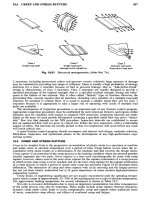
Boxes
Bulk
boxes
are
fabricated
from
corrugated
kraft
paper.
They
are
used
to
store
and
ship bulk
solid
materials
in
quantities
ranging
from
50
Ib
to
several hundred pounds.
A
single-wall
corrugated
kraft
board consists
of an
outside
liner,
a
corrugated
medium,
and an
inside
liner.
A
double-wall board
has
two
corrugated
mediums
sandwiched
between
three
liners.
The
specifications
for
bulk boxes
depend
on the
service
requirements;
600
lb/in.2
is
common
for
loads
up to
1000
Ib,
and 200
lb/in.2
for
100-lb
loads. Bulk boxes have
the
advantages
of
reclosing
and of
efficient
use of
storage
and
shipping
space,
called
cube. Disadvantages include
the
space needed
for
storage
of
unfilled
boxes
and
limited
reusability.
Figure
38.9
shows
important
characteristics
of
bulk boxes.
Folding cartons
are
used
for
shipping bulk
solids
contained
in
individual
bottles,
bags,
or
folding
boxes. Cartons
are of
less
sturdy construction than bulk boxes, because
the
contents
can
assist
in
supporting
vertically
imposed loads.
Fig.
38.8
Dimensions
of
multiwall
paper
bags.
Table
38.6
Dimensions
of
Multiwall
Paper
Bags
Valve
Dimensions
Filled-Face
Dimensions
Finished-Face
Dimensions
Tube
Dimensions
Bag
Type
Width
=
V=Gf±l/2
in.
Width
=
V=TT{+Q(
in'
T
[-1
in.
Width
=
WF
=
Wf
+
V2
in.
Length
=
LF
=
Lf
-
0.67G/
Thickness
=
GF
=
Gf
+
l/2
in.
Width
=
WF=Wf+
I
in.
Length
=
LF
=
Lf
-
0.61Gf
Thickness
=
GF
=
Gf
+ 1 in.
Width
=
WF=
Wf-
TT+
1 in.
Length-
LF
=
Lf
-
TT
+ 1 in.
Thickness
=
TF
=
TT
+
V2
in.
Width
=
Wf
=
Wt
-
Gf
Length
=
Lf
=
Lt
Gusset
=
Gf
Width
=
Wf
=
W,-Gf
Length
=
Lf
=
Lt
Gusset
=
Gf
Width
=
Wf
=
Wt
Length
=
Lf
=
Lt
-
(TT
+
TB)/2
- 1
Thickness
at top =
TT
Thickness
at
bottom
=
TB
Width
=
Wt=
Wf
+
Gf
Length
—
Lt
=
Lf
Width
=
Wt=Wf
+ Gf
Length
=
Lt
=
Lf
Width
=wt=Wf
Length
=
Lt
Sewn
open-mouth
Sewn
valve
Pasted
valve
Fig.
38.9
Bulk
boxes
and
cartons.
38.3.5
Transportation
of
Bulk
Materials
The
term
transportation
of
bulk materials refers
to the
movement
of raw
materials, fuels,
and
bulk
products
by
land, sea,
and
air.
A
useful definition
of a
bulk
shipment
is any
unit greater than
4000
Ib
or 40
ft3.
The
most
common
bulk carriers
are
railroad
hopper
cars,
highway
hopper
trucks, portable
bulk bins, barges,
and
ships. Factors affecting
the
choice
of
transportation include
the
characteristics
of
material size
of
shipment,
available transportation routes
from
source
to
destination
(e.g.,
highway,
rail,
water),
and the
time available
for
shipment.
Railroad
Hopper
Cars
Railroad
hopper
cars
are of
three basic designs:
1.
Covered,
with
bottom-unloading
ports
2.
Open,
with
bottom-unloading
ports
3.
Open,
without
unloading
ports
Gravity, pressure differential,
and fluidizing
unloading
systems
are
available with railroad
hopper
cars.
Loading
of
hopper
cars
can be
done
with
most
types
of
conveyors:
belt,
screw,
pneumatic,
and
so
on.
Unloading
of
bottom-unloading
hopper
cars
can be
managed
by
constructing
a
special
dumping
pit
beneath
the
tracks with
screw
or
belt
takeaway
conveyors.
Hopper
Trucks
Hopper
trucks
are
used
for
highway
transportation
of
bulk
solids materials.
The
most
common
types
include
(1)
closed type with
a
pneumatic
conveyor
unloading
system
and (2) the
open
dump
truck.
Fig.
38.10
Storage
drums.
With
the
first
type,
a
truck
can
discharge
its
cargo directly
into
a
storage
silo.
The
shipment weights
carried
by
trucks
depend
on
state
highway
load limits, usually
from
75,000-125,000
Ib.
38.4
UNIT
MATERIAL HANDLING
38.4.1
Introduction
Unit material handling involves
the
movement
and
storage
of
unit loads,
as
defined
in
Section
38.1.
Examples
include
automobile
body
components,
engine blocks, bottles, cans, bags,
pallets
of
boxes,
bins
of
loose parts,
and so on. As the
previous definition implies,
the
word
unit
refers
to the
single
entity
that
is
handled.
That
entity
can
consist
of a
single item
or
numerous
items
that
have been
unitized
for
purposes
of
movement
and
storage.
Outside dimensions
Drum
type
,
Dm.,in.
Height,
in.
55-gal.
lever
top 21
403/<
55-gal.
lever
top
231/z
30^4
55-gal.
lever
top 22
34
V4
41 -
gal.
lever
top
20'/2
30
f/4
30-gal.
lever
top 19 26
1/4
6.28-cu.ft.rectangular
17Vs*
37
Vz
55-gal.
liquid
22 37
Vz
30-go!,
liquid
19 28
55-gal.
fiber
2O3/s
40V4
30-gal,
fiber
[
17Ve
|
30V4
*
Side
dimension,
square
This section discusses
some
of the
procedures
employed
in
material-handling system design,
and
describes various categories, with
examples,
of
material-handling
equipment
used
in
handling unit
loads.
38.4.2
Analysis
of
Systems
for
Material Handling
Material handling
is an
indispensable element
in
most
production
and
distribution systems. Yet, while
material handling
is
generally considered
to add
nothing
to the
value
of the
materials
and
products
that
flow
through
the
system,
it
does
add to
their
cost.
In
fact,
it has
been
estimated
that
30%-60%
of the
end-price
of a
product
is
related
to the
cost
of
material handling. Therefore,
it
is
essential
that
material
handling systems
be
designed
and
operated
as
efficiently
and
cost-effectively
as
possible.
The
following steps
can be
used
in
analyzing production systems
and
solving
the
inherent
material-handling problems:
1.
Identify
and
define
the
problem(s).
2.
Collect relevant data.
3.
Develop
a
plan.
4.
Implement
the
solution.
Unfortunately,
when
most
engineers perceive
that
a
material-handling
problem
exists,
they skip
directly
to
step
4;
that
is,
they begin looking
for
material-handling
equipment
that
will address
the
symptoms
of the
problem
without looking
for the
underlying root causes
of the
problem,
which
may
be
uncovered
by
execution
of all
four steps
listed
above.
Thus,
the
following sections explain
how to
organize
a
study
and
provide
some
tools
to use in
an
analysis
of a
material-handling system according
to
this
four-step procedure.
38.4.3
Identifying
and
Defining
the
Problem
For a new
facility,
the
best
way to
begin
the
process
of
identifying
and
defining
the
problems
is to
become
thoroughly familiar with
all of the
products
to be
produced
by the
facility,
their
design
and
component
parts,
and
whether
the
component
parts
are to be
made
in the
facility
or
purchased
from
vendors.
Then,
one
must
be
thoroughly
knowledgeable
about
the
processes required
to
produce
each
part
and
product
to be
made
in the
facility.
One
must
also
be
cognizant
of the
production schedules
for
each
part
and
product
to be
produced;
that
is,
parts
or
products
produced
per
shift,
day,
week,
month,
year,
and so on.
Finally,
one
must
be
intimately familiar with
the
layout
of the
facility
in
which
production will take place;
not
just
the
area layout,
but the
volume
(or
cubic
space)
available
for
handling materials throughout
the
facility.
Ideally,
the
persons
or
teams
responsible
for the
design
of
material-handling systems
for a new
facility
will
be
included
and
involved
from
the
initial
product design stage through process design,
schedule design,
and
layout design.
Such
involvement
in a
truly
concurrent engineering approach
will
contribute greatly
to the
efficient
and
effective handling
of
materials
when
the
facility
becomes
operational.
In
an
existing
facility,
the
best
way to
begin
the
process
of
identifying
and
defining
the
problems
is
to
tour
the
facility,
looking
for
material-handling aspects
of the
various processes observed.
It is
a
good
idea
to
take along
a
checklist, such
as
that
shown
in
Fig.
38.11.
Another
useful guide
is the
Material
Handling
Institute
(MHI)
list
of
"The
Twenty
Principles
of
Material
Handling,"
as
given
in
Fig.
38.12.
Once
the
problem
has
been
identified,
its
scope
must
be
defined.
For
example,
if
most
of the
difficulties
are
found
in one
area
of the
plant, such
as
shipping
and
receiving,
the
study
can be
focused there.
Are the
difficulties
due to
lack
of
space?
Or is
part
of the
problem
due to
poor training
of
personnel
in
shipping
and
receiving?
In
defining
the
problem,
it is
necessary
to
answer
the
basic
questions
normally asked
by
journalists:
Who?
what?
when?
where?
why?
38.4.4
Collecting
Data
In
attempting
to
answer
the
journalistic questions above,
all
relevant data
must
be
collected
and
analyzed.
At a
minimum,
the
data collection
and
analysis
must
be
concerned
with
the
products
to
be
produced
in the
facility,
the
processes (fabrication, assembly,
and so on)
used
to
produce
each
product,
the
schedule
to be met in
producing
the
products,
and the
facility
layout (three-dimensional
space allocation) supporting
the
production processes.
Some
useful data
can be
obtained
by
interviewing
management,
supervisors, operators, vendors,
and
competitors,
by
consulting available technical
and
sales
literature,
and
through personal obser-
vation.
However,
most
useful data
are
acquired
by
systematically charting
the flows of
materials
and
the
movements
that
take place within
the
plant. Various graphical techniques
are
used
to
record
and
analyze
this
information.
An
assembly
chart,
shown
in
Fig.
38.13,
is
used
to
illustrate
the
composition
of the
product,
the
relationship
among
its
component
parts,
and the
sequence
in
which
components
are
assembled.
Fig.
38.11
Material-handling
checklist.
The
operations process chart,
shown
in
Fig.
38.14,
provides
an
even
more
detailed depiction
of
material
flow
patterns, including sequences
of
production
and
assembly
operations.
It
begins
to
afford
an
idea
of the
relative
space requirements
for the
process.
The flow
process chart,
illustrated
in
Fig. 38.15, tabulates
the
steps involved
in a
process, using
a
set
of
standard
symbols
adopted
by the
American
Society
of
Mechanical
Engineers
(ASME).
Shown
at
the top of the
chart, these
five
symbols
allow
one to
ascribe
a
specific
status
to an
item
at
each
step
in
processing.
The
leftmost
column
in the flow
process chart
lists
the
identifiable
activities
comprising
the
process,
in
sequential order.
In the
next
column,
one of the five
standard
symbols
is
selected
to
identify
the
activity
as an
operation, transportation, inspection, delay,
or
storage.
The
remaining
columns
permit
the
recording
of
more
detailed information.
Note
that
in the flow
process chart
in
Fig.
38.16,
for
each
step
recorded
as a
"transport,"
a
distance
(in
feet)
is
recorded. Also,
in
some
of the
leftmost
columns
associated with
a
transport
activity,
the
type
of
material handling
equipment
used
to
make
the
move
is
recorded—for
example,
"fork
lift."
However,
material-handling equipment could
be
used
for any of the
activities
shown
in
this
chart.
For
example,
automated storage
and
retrieval
systems
(AS/RSs)
can be
used
to
store
materials,
accumulating conveyors
can be
used
to
queue materials during
a
delay
in
processing,
or
conveyors
can be
configured
as a
moving
assembly
line
so
that
operations
can be
performed
on the
product while
it is
being transported through
the
facility.
In
the
columns
grouped under
the
heading
possibilities,
opportunities
for
improvement
or
sim-
plification
of
each
activity
can be
noted.
The flow
diagram, depicted
in
Fig.
38.16,
provides
a
graphical record
of the
sequence
of
activities
required
in the
production process,
superimposed
upon
an
area layout
of a
facility.
This graphical
technique uses
the
ASME
standard
symbol
set and
augments
the flow
process chart.
The
"from-to"
chart,
illustrated
in
Fig.
38.17,
provides
a
matrix representation
of the
required
number
of
material
moves
(unit loads)
in the
production process.
A
separate
from-to
chart
can
also
be
constructed
that
contains
the
distances materials
must
be
moved
between
activities
in the
produc-
tion
process.
Of
course, such
a
chart
will
be
tied
to a
specific
facility
layout
and
usually contains
assumptions about
the
material-handling equipment
to be
used
in
making
the
required
moves.
The
activity
relationship chart,
shown
in
Fig.
38.18,
can be
used
to
record
qualitative
information
regarding
the flow of
materials
between
activities
or
departments
in a
facility.
Read
like
a
highway
mileage
table
in a
typical
road
atlas,
which
indicates
the
distances
between
pairs
of
cities,
the
activity
relationship
chart allows
the
analyst
to
record
a
qualitative
relationship
that
should
exist
between
each
pair
of
activities
or
departments
in a
facility
layout.
The
relationships recorded
in
this
chart
show
the
importance
that
each
pair
of
activities
be
located
at
varying degrees
of
closeness
to
each
Material
Handling
Checklist
lH
Is the
material
handling equipment
more
than
10
years
old?
D Do you use a
wide
variety
of
makes
and
models
which
require
a
high spare parts
inventory?
D Are
equipment
breakdowns
the
result
of
poor
preventive
maintenance?
D
Do the
lift
trucks
go too
far
for
servicing?
D
Are
there
excessive
employee
accidents
due to
manual
handling
of
materials?
D Are
materials weighing
more
than
50
pounds
handled manually?
D Are
there
many
handling
tasks
that
re-
quire
2 or
more
employees?
Q
Are
skilled
employees
wasting time han-
dling
materials?
D
Does
material
become
congested
at
any
point?
D Is
production
work
delayed
due to
poorly
scheduled
delivery
and
removal
of
mate-
rials?
D
Is
high
storage
space
being
wasted?
D Are
high
demurrage
charges
experi-
enced?
D
Is
material being
damaged
during
han-
dling?
G Do
shop
trucks operate empty
more
than
20% of the
time?
Q
Does
the
plant
have
an
excessive number
of
rehandling
points?
Q Is
power
equipment
used
on
jobs
that
could
be
handled
by
gravity?
D Are too
many
pieces
of
equipment being
used,
because
their
scope
of
activity
is
confined?
D Are
many
handling operations
unneces-
sary?
Q Are
single
pieces
being handled
where
unit
loads
could
be
used?
D Are
floors
and
ramps
dirty
and
in
need
of
repair?
Q
Is
handling
equipment
being
overloaded?
D Is
there
unnecessary
transfer
of
material
from
one
container
to
another?
D Are
inadequate
storage
areas
hampering
efficient
scheduling
of
movement?
Q Is
it
difficult
to
analyze
the
system
be-
cause
there
is no
detailed
flow
chad?
D Are
indirect
labor
costs
too
high?
The 20
Principles
of
Material
Handling
1.
Planning Principle. Plan
all
material
handling
and
storage
activities
to
obtain
maximum
overall
operating efficiency.
2.
Systems
Principle,
integrate
as
many
handling
activities
as is
practical
into
a
coor-
dinated
system
of
operations,
covering
ven-
dor,
receiving, storage,
production,
inspec-
tion,
packaging,
warehousing,
shipping,
transportation,
and
customer.
3.
Material
Row
Principle. Provide
an
op-
eration
sequence
and
equipment
layout
optimizing
material flow.
4.
Simplification
Principle.
Simplify
han-
dling
by
reducing,
eliminating,
or
combining
unnecessary
movements
and/or
equipment.
5.
Gravity Principle.
Utilize
gravity
to
move
material wherever
practical.
6.
Space
Utilization
Principle.
Make
op-
timum
utilization
of
building
cube.
7.
Unit
Size
Principle. Increase
the
quan-
tity,
size,
or
weight
of
unit
toads or flow
rate.
8.
Mechanization
Principle.
Mechanize
handling
operations.
9.
Automation
Principle. Provide automa-
tion
to
include
production,
handling,
and
storage
functions.
10.
Equipment
Selection Principle.
In
selecting
handling
equipment consider
all
aspects
of the
material
handled
— the
movement
and the
method
to be
used.
11.
Standardization
Principle. Standardize
handling
methods
as
well
as
types
and
sizes
of
handling equipment.
12.
Adaptability Principle.
Use
methods
and
equipment
that
can
best perform
a
vari-
ety
of
tasks
and
applications
where
special
purpose
equipment
is not
justified.
13.
Dead
Weight
Principle.
Reduce
ratio
of
dead
weight
of
mobile handling equipment
to
toad
carried.
14.
Utilization Principle. Plan
for
optimum
utilization
of
handling equipment
and
man-
power.
15.
Maintenance
Principle. Plan
for
preven-
tive
maintenance
and
scheduled repairs
of
all
handling
equipment.
16.
Obsolescence
Principle.
Replace
ob-
solete handling
methods
and
equipment
when
more
efficient
methods
or
equipment
will
improve operations.
17.
Control
Principle.
Use
material han-
dling
activities
to
improve control
of
produc-
tion,
inventory
and
order handling.
18.
Capacity
Principle.
Use
handling
equipment
to
help achieve desired produc-
tion
capacity.
19.
Performance
Principle. Determine
ef-
fectiveness
of
handling performance
in
terms
of
expense
per
unit
handled.
20.
Safety
Principle. Provide
suitable
methods
and
equipment
for
safe
handling.
Fig.
38.13
Assembly
chart.
Fig.
38.12
Twenty
principles
of
material
handling.
Fig. 38.14 Operations
process
chart.
other (using
an
alphabetic
symbol)
and the
reason
for the
assignment
of
that
rating
(using
a
numeric
symbol).
Together
these charting techniques provide
the
analyst extensive,
qualitative
data about
the
layout
to
support
a
production process.
This
is
very useful
from
the
standpoint
of
designing
a
material
handling system.
38.4.5
Unitizing
Loads
Principle
number
7 of the
MHI
Twenty
Principles
of
Material
Handling
(Fig.
38.12)
is the
unit
size
principle,
also
known
as the
unit
load principle,
which
states,
"
Increase
the
quantity, size,
or
weight
of
unit
loads
or flow
rate."
The
idea behind
this
principle
is
that
if
materials
are
consolidated into
large
quantities
or
sizes,
fewer
moves
of
this
material will have
to be
made
to
meet
needs
of the
production processes.
Therefore,
less
time will
be
required
to
move
the
unitized material than
that
required
to
move
the
same
quantity
of
non-unitized material.
So,
unitizing materials usually
results
in
low-cost,
efficient
material-handling practices.
The
decision
to
unitize
is
really
a
design decision
in
itself,
as
illustrated
in
Fig.
38.19.
Unitization
can
consist
of
individual pieces through unit
packs,
inner packs, shipping cartons,
tiers on
pallets,
pallet
loads, containers
of
pallets,
truckloads,
and so on. The
material-handling
system
must
then
be
designed
to
accommodate
the
level
of
unitized parts
at
each step
of the
production process.
As
shown
in
Fig.
38.19,
once
products
or
components
have
been
unitized
into
shipping cartons,
further
consolidation
may
easily
be
achieved
by
placing
the
cartons
on a
pallet,
slip
sheet,
or
some
other load-support
medium
for
layers
(or
tiers)
of
cartons
comprising
the
unit load. Since
the
unit
load principle requires
the
maximum
utilization
of the
area
on the
pallet
surface, another design
problem
is to
devise
a
carton stacking pattern
that
achieves
this
objective.
Examples
of
pallet
loading
patterns
that
can
achieve optimal surface utilization
are
illustrated
in
Fig.
38.20.
Charts
of
such
patterns
are
available
from
the
U.S.
Government
(General
Services Administration).
There
are
also
a
number
of
providers
of
computer
software
programs
for
personal
computers
that
generate
pallet-
loading patterns.
Highly
automated
palletizer
machines
as
well
as
palletizing robots
are
available
that
can be
programmed
to
form
unit loads
in any
desired configuration.
Depending
upon
the
dimensions
of the
cartons
to be
palletized,
and the
resulting optimal loading pattern selected,
the
palletized load
may
be
inherently stable
due to
overlapping
of
cartons
in
successive
tiers; for
example,
the
various pin-
wheel
patterns
shown
in
Fig.
38.20.
However,
other pallet-loading patterns
may be
unstable, such
as the
block pattern
in
Fig.
38.21,
particularly
when
cartons
are
stacked several
tiers
high.
In
such instances,
the
loads
may be
stabilized
by
stretch-wrapping
the
entire
pallet
load with
plastic
film, or by
placing
bands
around
the
individual
Fig.
38.15
Flow
process
chart.
tiers.
The
wrapping
or
banding operations themselves
can be
automated
by use of
equipment
that
exists
in the
market today.
Once
the
unit
load
has
been formed,
there
are
only four basic
ways
it
can be
handled while being
moved.
These
are
illustrated
in
Fig.
38.22
and
consist
of the
following:
1.
Support
the
load
from
below.
2.
Support
or
grasp
the
load
from
above.
3.
Squeeze
opposing
sides
of the
load.
4.
Pierce
the
load.
Name
Results
Operation
Produces,
prepares,
and
accomplishes
Transportation
Moves
Inspection Verifies
Delay
Interfere,
waits
Storage
Keeps,
retains
1.
Receive
raw
materials
2.
Inspect
3.
Move
by
fork
lift
4.
Store
5.
Move
by
fork
lift
6. Set up and
7.
Moved
by
printer
8.
Stack
at end of
printer
9.
Move
to
stripping
10.
Delay
11.
Being stripped
12.
Move
to
temp,
storage
13.
Storage
14.
Move
to
folders
15.
Delay
16.
Set up,
fold,
glue
17.
Mechanically
moved
18.
Stack, count, crate
19.
Move
by
fork
lift
20.
Storage
Fig.
38.16
Flow
diagram.
These
handling
methods
are
implemented
individually,
or in
combination,
by
commercially
available
material-handling
equipment
types.
38.5 MATERIAL-HANDLING
EQUIPMENT CONSIDERATIONS
AND
EXAMPLES
38.5.1
Developing
the
Plan
Once
the
material-handling
problem
has
been
identified
and the
relevant data
have
been
collected
and
analyzed,
the
next step
in the
design process
is to
develop
a
plan
for
solving
the
problem.
This
usually involves
the
design
and/or
selection
of
appropriate types, sizes,
and
capacities
of
material-
handling
equipment.
In
order
to
properly select material handling
equipment,
it
must
be
realized
that
in
most
cases,
the
solution
to the
problem
does
not
consist
merely
of
selecting
a
particular piece
of