Mechanical Engineer´s Handbook P12 pptx
Bạn đang xem bản rút gọn của tài liệu. Xem và tải ngay bản đầy đủ của tài liệu tại đây (1.11 MB, 24 trang )
the
total energy values
for
static
and
dynamic conditions
are
identical.
If the
velocity
is
increased,
the
impact values
are
considerably reduced.
For
further
information,
see
Ref.
10.
10.6.6
Steady
and
Impulsive
Vibratory
Stresses
For
steady vibratory stresses
of a
weight,
W,
supported
by a
beam
or
rod,
the
deflection
of the
bar,
or
beam, will
be
increased
by the
dynamic magnification
factor.
The
relation
is
given
by
dynamic
=
Static
x
dynamic magnification factor
An
example
of the
calculating procedure
for the
case
of no
damping losses
is
»„
-
S^
X
i
_
(
^
)2
(10.65)
where
a) is the
frequency
of
oscillation
of the
load
and
O)
n
is the
natural
frequency
of
oscillation
of
a
weight
on the
bar.
For the
same beam excited
by a
single sine pulse
of
magnitude
A
in./sec
2
and a sec
duration,
then
for t < a a
good approximation
is
S
static
(A/g)
T
1
/
a}\
"I
«<*
=
t
J^/y
[sin
- -
^
(-)
sin
^J
(10.66)
\47TOjJ
where
A/g
is the
number
of
g's
and
o>
is
TT/a.
10.7
SHAFTS,
BENDING,
AND
TORSION
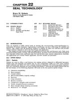
10.7.1
Definitions
TORSIONAL
STRESS.
A bar is
under
torsional
stress when
it is
held
fast
at one
end,
and a
force
acts
at
the
other
end to
twist
the
bar.
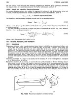
In a
round
bar
(Fig. 10.23) with
a
constant
force
acting,
the
straight
line
ab
becomes
the
helix
ad,
and a
radial line
in the
cross section,
ob,
moves
to the
position
od. The
angle
bad
remains constant while
the
angle
bod
increases with
the
length
of the
bar. Each cross section
of the bar
tends
to
shear
off the one
adjacent
to it, and in any
cross section
the
shearing stress
at any
point
is
normal
to a
radial line drawn through
the
point. Within
the
shearing proportional limit,
a
radial line
of the
cross section remains straight
after
the
twisting
force
has
been applied,
and the
unit shearing stress
at any
point
is
proportional
to its
distance
from
the
axis.
TWISTING MOMENT,
T,
is
equal
to the
product
of the
resultant,
F, of the
twisting forces, multiplied
by
its
distance
from
the
axis,
p.
RESISTING MOMENT,
T
r
,
in
torsion,
is
equal
to the sum of the
moments
of the
unit shearing stresses
acting
along
a
cross section with respect
to the
axis
of the
bar.
If dA is an
elementary area
of the
section
at a
distance
of z
units
from
the
axis
of a
circular
shaft
(Fig.
10.23£),
and c is the
distance
from
the
axis
to the
outside
of the
cross section where
the
unit shearing stress
is
r,
then
the
unit
shearing
stress acting
on dA is
(TZ/C)
dA,
its
moment with respect
to the
axis
is
(TZ
2
Ic)
dA,
an
the
sum of all the
moments
of the
unit shearing
stresses
on the
cross section
is
J
(rz
2
/c)
dA. In
Fig.
10.23
Round
bar
subject
to
torsional
stress.
this expression
the
factor
J
z
2
dA
is the
polar moment
of
inertia
of the
section with respect
to the
axis. Denoting this
by 7, the
resisting moment
may be
written
rJIc.
THE
POLAR MOMENT
OF
INERTIA
of a
surface about
an
axis through
its
center
of
gravity
and
perpendicular
to the
surface
is the sum of the
products obtained
by
multiplying each elementary
area
by the
square
of its
distance
from
the
center
of
gravity
of its
surface;
it is
equal
to the sum
of
the
moments
of
inertia taken with respect
to two
axes
in the
plane
of the
surface
at right
angles
to
each other passing through
the
center
of
gravity.
It is
represented
by
/,
inches
4
.
For the
cross
section
of a
round
shaft,
J
=
1
X
32
TrJ
4
or
V
2
TTr
4
(10.67)
For a
hollow
shaft,
/
-
'/32TT(J
4
-
d
4
)
(10.68)
where
d is the
outside
and
d
1
is the
inside diameter, inches,
or
J
=
y
2
7r(r
4
-
r
4
)
(10.69)
where
r is the
outside
and
r
l
the
inside radius, inches.
THE
POLAR RADIUS
OF
GYRATION,
k
p
,
sometimes
is
used
in
formulas;
it is
defined
as the
radius
of
a
circumference along which
the
entire area
of a
surface might
be
concentrated
and
have
the
same
polar moment
of
inertia
as the
distributed area.
For a
solid circular section,
k
2
p
=
Vsd
2
(10.70)
For a
hollow circular section,
k
2
=
1
X
8
(J
2
-
d
2
)
(10.71)
10.7.2
Determination
of
Torsional
Stresses
in
Shafts
Torsion
Formula
for
Round
Shafts
The
conditions
of
equilibrium require that
the
twisting moment,
T, be
opposed
by an
equal resisting
moment,
T
r
,
so
that
for the
values
of the
maximum unit shearing stress,
r,
within
the
proportional
limit,
the
torsion
formula
for
round
shafts
becomes
T
r
=
T=T-
(10.72)
if
T is in
pounds
per
square inch, then
T
r
and T
must
be in
pound-inches,
/
is in
inches
4
,
and c is in
inches.
For
solid round
shafts
having
a
diameter,
d,
inches,
J
=
1
X
32
TrJ
4
and c =
1
X
2
J
(10.73)
and
1
(~\T
T
=
1
A
6
TTd
3
T
or
T=
—-
(10.74)
TTd
3
For
hollow round
shafts,
7T(d
4
~
d
4
)
J
=
—-
and c =
l
/
2
d
(10.75)
and
the
formula
becomes
TTr(J
4
-
J
4
)
167
1
J
T=
\
or
T=
a
(10.76)
16J
Tr(J
4
-
d
4
}
The
torsion
formula
applies only
to
solid circular
shafts
or
hollow circular
shafts,
and
then only
when
the
load
is
applied
in a
plane perpendicular
to the
axis
of the
shaft
and
when
the
shearing
proportional limit
of the
material
is not
exceeded.
Shearing
Stress
in
Terms
of
Horsepower
If
the
shaft
is to be
used
for the
transmission
of
power,
the
value
of
T,
pound-inches,
in the
above
formulas
becomes
63,030//VAf,
where
H
=
horsepower
to be
transmitted
and N
=
revolutions
per
minute.
The
maximum unit shearing stress, pounds
per
square inch, then
is
321
0007/
For
solid round
shafts:
r
=
'——
(10.77)
Nd
^91
OOOfjsl
For
hollow round
shafts:
r =
'
——
(10.78)
N(d
-U
1
)
If
T is
taken
as the
allowable unit shearing stress,
the
diameter,
d,
inches, necessary
to
transmit
a
given horsepower
at a
given
shaft
speed
can
then
be
determined. These formulas give
the
stress
due
to
torsion only,
and
allowance must
be
made
for any
other loads,
as the
weight
of
shaft
and
pulley,
and
tension
in
belts.
Angle
of
Twist
When
the
unit shearing stress
r
does
not
exceed
the
proportional limit,
the
angle
bod
(Fig.
10.23)
for
a
solid round
shaft
may be
computed
from
the
formula
O
=
£
(10.79)
(jJ
where
6
=
angle
in
radians;
/ =
length
of
shaft
in
inches;
G =
shearing modulus
of
elasticity
of the
material;
T =
twisting moment, pound-inches. Values
of G for
different
materials
are
steel,
12,000,000;
wrought iron,
10,000,000;
and
cast iron,
6,000,000.
When
the
angle
of
twist
on a
section
begins
to
increase
in a
greater ratio than
the
twisting moment,
it
may be
assumed that
the
shearing stress
on the
outside
of the
section
has
reached
the
proportional
limit.
The
shearing stress
at
this point
may be
determined
by
substituting
the
twisting moment
at
this
instant
in the
torsion formula.
Torsion
of
Noncircular
Cross
Sections
The
analysis
of
shearing stress distribution along noncircular cross sections
of
bars under torsion
is
complex.
By
drawing
two
lines
at right
angles through
the
center
of
gravity
of a
section before
twisting,
and
observing
the
angular distortion
after
twisting,
it as
been
found
from
many experiments
that
in
noncircular sections
the
shearing unit stresses
are not
proportional
to
their distances
from
the
axis. Thus
in a
rectangular
bar
there
is no
shearing stress
at the
corners
of the
sections,
and the
stress
at
the
middle
of the
wide side
is
greater than
at the
middle
of the
narrow side.
In an
elliptical
bar
the
shearing stress
is
greater along
the flat
side than
at the
round side.
It has
been
found
by
tests
5
'
11
as
well
as by
mathematical analysis that
the
torsional resistance
of
a
section, made
up of a
number
of
rectangular parts,
is
approximately equal
to the sum of the
resistances
of the
separate parts.
It is on
this basis
that
nearly
all the
formulas
for
noncircular sections
have
been developed.
For
example,
the
torsional resistance
of an
I-beam
is
approximately equal
to
the
sum of the
torsional resistances
of the web and the
outstanding
flanges. In an
I-beam
in
torsion
the
maximum shearing stress will occur
at the
middle
of the
side
of the
web, except where
the flanges
are
thicker than
the
web,
and
then
the
maximum stress will
be at the
midpoint
of the
width
of the
flange.
Reentrant angles,
as
those
in
I-beams
and
channels,
are
always
a
source
of
weakness
in
members subjected
to
torsion. Table 10.8 gives values
of the
maximum unit shearing stress
r
and
the
angle
of
twist
6
induced
by
twisting bars
of
various cross sections,
it
being assumed that
r is not
greater than
the
proportional limit.
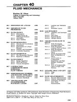
Torsion
of
thin-wall closed sections, Fig. 10.24,
T
= 2qA
(10.80)
q
=
rt
(10.81)
,.^Z^L^Z
(10
.82)
' L
2A2AG
t GJ
^
}
where
5
is the arc
length around area
A
over which
r
acts
for a
thin-wall
section; shear buckling
should
be
checked. When more than
one
cell
is
used
1
'
12
or if
section
is not
constructed
of a
single
material,
12
the
calculations become more involved:
4/t2
J
=
TTTt
(10.83)
§
dslt
Table 10.8 Formulas
for
Torsional Deformation
and
Stress
TL
T
General formulas:
B
=•
—-,
T
=
—
,
where
9
=»
angle
of
twist, radians;
T =
twisting moment,
in lb;
KG Q
L —
length,
in.;
r —
unit shear
stress,
psi;
G —
modulus
of
rigidity, psi;
K
1
in.
4
;
and Q,
in.
3
are
func-
tions
of the
cross section.
TL
Shape Formula
for K in
6
=
—
Formula
for
Shear Stress
./Y(J
«
=
£
~%
K
=
1/32TW
4
~
<*1
4
)
T
=
]6Td
r(d*
-
d!
4
)
K
-
2/3
^
3
T
=
JI_
2irr«2
JTO^
r==
-^
K
^TT
2
-^
2
o
—
ai
7roi
3
bi3
4
ai
2T
K
-
^TfJs
[(I
+
5)
~
l]
q
_
6-61
T
-
,a^d+^-n
&1
6
V^
_
2OT
~80~
T
^T
1
097
7
K =
2.696*
T =
±?j±
ab3r16
336
Vl-
b4>
ll
r
_
Oa+
1.86)7
^
TeLl"
a
V
r2a4yj
a2№
^
=
2^
2
(a
-
<2)
2
(6
-
<i)
2
r
=
7
a<2
+
Ui
-
t£
-
tr
2/2(a
-
^)
(6
-
ti)
K
=
0.140664
r
=
4
^I
Ultimate
Strength
in
Torsion
In
a
torsion failure,
the
outer
fibers of a
section
are the first to
shear,
and the
rupture extends toward
the
axis
as the
twisting
is
continued.
The
torsion formula
for
round
shafts
has no
theoretical basis
after
the
shearing stresses
on the
outer
fibers
exceed
the
proportional limit,
as the
stresses along
the
section then
are no
longer proportional
to
their distances
from
the
axis.
It is
convenient, however,
to
compare
the
torsional strength
of
various materials
by
using
the
formula
to
compute values
of
r
at
which
rupture takes place. These computed values
of the
maximum stress sustained before rupture
are
somewhat higher
for
iron
and
steel than
the
ultimate strength
of the
materials
in
direct shear.
Computed
values
of the
ultimate strength
in
torsion
are
found
by
experiment
to be:
cast iron,
30,000
psi; wrought iron,
55,000
psi; medium steel,
65,000
psi; timber,
2000
psi. These computed values
of
twisting
strength
may be
used
in the
torsion formula
to
determine
the
probable twisting moment that
will
cause rupture
of a
given round
bar or to
determine
the
size
of a bar
that will
be
ruptured
by a
given
twisting moment.
In
design, large factors
of
safety
should
be
taken, especially when
the
stress
is
reversed
as in
reversing engines
and
when
the
torsional stress
is
combined with other stresses
as
in
shafting.
Fig.
10.24
Thin-walled
tube.
Table
10.8
(Continued)
TT
T
General
formulas:
6 —
-^-
, r
•»
— ,
where
6
«•
angle
of
twist,
radians;
T
«•
twisting
moment,
in Ib;
KG Q
L —
length,
in.;
r
«•
unit
shear
stress,
psi;
G
=
modulus
of
rigidity,
psi;
K,
in.
4
;
and Q,
in.
9
are
func-
tions
of the
cross
section.
TL
Shape
Formula
for K in 9 — —
Formula
for
Shear
Stress
KG
r
•»
fillet
radius
D —
diameter largest
inscribed
circle
.
For
all
solid
section*
of
irregular
A
-
ZA
1
+
A
2
+
t*U
form
the
maxi
mum
shear
8treM
K.
—
06
3
F-
— O
21
-
f
I —
-^-\
"1
occurs
at or
very
near
one of the
1
L3
o
\
I2a
4
/J
points where
the
largest
inscribed
—
I
J
7
/f4
\
-i
circle
touches
the
boundary,
and
X
2
-
«P
- -
0.105?
(
1
— ) of
these,
at the one
where
the
L
3
c
^
•
92c
'
J
curvature
of
the
boundary
is
alge-
b
/
n
nj
n
n
_,
r\
braically
least.
(Convexity
rep-
«
-
-
^0.07
+
0.076
-J
regent8
P
08
J
11
^
concavity
nega
_
tive, curvature
of the
boundary.)
X
«
2Xi
-f
X
2
-f
ZaD
4
At
a
P°
int
where
the
curvature
is
.
.
M \
T
positive
(boundary
of
section
Xi
—
06*
J- —
0.21
-
(
1
—-
)
J
straight
or
convex)
this
maximum
L3
o
\
I2o*/
J
stress
is
given
approximately
by:
X
2
-
V
3
cd
3
„0
T
t/ r\
T
"
°~L
C
Ql
T
~
K
C
a-
-(0.15+
0.1-
r
)
L
K
ti
\
^
b/
where
t
- 6
if
6 <d
c-
2
x
t
- d if
d
< b
1+
£**
ti-biSb>d
16A
*
"">»
E
1+
-(S-:-!)]
X
-
Xi
-f
Xt
+
ctD
4
where
D -
diameter
of
largest
in-
v
,.fl
*•»•&/•
&
\~]
scribed
circle,
r -
r
a
da
us
of
cur-
Xi
-
o63
^-
-
0.21
^I-
72^JJ
vature
of
boundary
at the
point
(positive
for
this
case),
A
••
area
/C
2
-
cd»
ri
-
O.J05-
(\
-
—^l
of
tbe
»<*«»•
L3
c
\
192(H/J
a
- -
(0.07
+
0.076
f\
d
\ b/
10.7.3
Bending
and
Torsional
Stresses
The
stress
for
combined bending
and
torsion
can be
found
from
Eqs. (10.20), shear theory,
and
(10.22), distortion energy, with
a
y
= O:
T=KfHf
For
solid round rods, this equation reduces
to
cr
w
16
,
^
-
—-
VM
2
+
T
2
(10.85)
2
Trd
3
From distortion energy
'-,/IfRrF
For
solid round rods,
the
equation yields
o-
=
-^r
VM
2
+
3
AT
2
(10.87)
rar
10.8
COLUMNS
10.8.1
Definitions
A
COLUMN
OR
STRUT
is a bar or
structural member under axial compression, which
has an
unbraced
length greater than about eight
or ten
times
the
least dimension
of its
cross section.
On
account
of
its
length,
it is
impossible
to
hold
a
column
in a
straight
line
under
a
load;
a
slight sidewise
bending always occurs, causing
flexural
stresses
in
addition
to the
compressive
stresses induced
directly
by the
load.
The
lateral
deflection
will
be in a
direction perpendicular
to
that axis
of the
cross section about which
the
moment
of
inertia
is the
least. Thus
in
Fig.
10.25«
the
column will
bend
in a
direction perpendicular
to
aa,
in
Fig.
10.25/?
it
will bend perpendicular
to aa or
bb,
and
in
Fig.
10.25c
it is
likely
to
bend
in any
direction.
RADIUS
OF
GYRATION
of a
section with respect
to a
given axis
is
equal
to the
square root
of the
quotient
of the
moment
of
inertia with respect
to
that axis, divided
by the
area
of the
section, that
is
k
=
Vz
;
i
=
k2
(10
-
88)
where
7
is the
moment
of
inertia
and A is the
sectional area. Unless otherwise mentioned,
an
axis
Fig.
10.25
Column
end
designs.
through
the
center
of
gravity
of the
section
is the
axis considered.
As in
beams,
the
moment
of
inertia
is an
important factor
in the
ability
of the
column
to
resist bending,
but for
purposes
of
computation
it is
more convenient
to use the
radius
of
gyration.
LENGTH
OF A
COLUMN
is the
distance between points unsupported against lateral deflection.
SLENDERNESS RATIO
is the
length
/
divided
by the
least radius
of
gyration
k,
both
in
inches.
For
steel,
a
short column
is one in
which
Uk
< 20 or 30, and its
failure under load
is due
mainly
to
direct compression;
in a
medium-length column,
Uk=
about
30-175,
failure
is by a
combination
of
direct compression
and
bending;
in a
long column,
Ilk
>
about
175-200,
failure
is
mainly
by
bending.
For
timber columns these ratios
are
about
0-30, 30-90,
and
above
90
respectively.
The
load which will cause
a
column
to
fail
decreases
as
Ilk
increases.
The
above ratios apply
to
round-
end
columns,
If the
ends
are fixed
(see
below),
the
effective
slenderness
ratio
is
one-half that
for
round-end columns,
as the
distance between
the
points
of
inflection
is
one-half
of the
total length
of
the
column.
For flat
ends
it is
intermediate between
the
two.
CONDITIONS
OF
ENDS.
The
various conditions which
may
exist
at the
ends
of
columns usually
are
divided into
four
classes:
(1)
Columns with round ends;
the
bearing
at
either
end has
perfect
freedom
of
motion,
as
there would
be
with
a
ball-and-socket joint
at
each
end.
(2)
Columns with
hinged ends; they have perfect freedom
of
motion
at the
ends
in one
plane,
as in
compression
members
in
bridge trusses where loads
are
transmitted through
end
pins.
(3)
Columns with
flat
ends;
the
bearing surface
is
normal
to the
axis
of the
column
and of
sufficient
area
to
give
at
least
partial
fixity to the
ends
of the
columns against lateral deflection.
(4)
Columns with
fixed
ends;
the
ends
are rigidly
secured,
so
that under
any
load
the
tangent
to the
elastic curve
at the
ends
will
be
parallel
to the
axis
in its
original position.
Experiments prove that columns with
fixed
ends
are
stronger than columns with
flat,
hinged,
or
round ends,
and
that columns with round ends
are
weaker than
any of the
other types. Columns
with
hinged ends
are
equivalent
to
those with round ends
in the
plane
in
which they have
free
movement; columns with
flat
ends have
a
value intermediate between those with
fixed
ends
and
those with round ends.
If
often
happens that columns have
one end fixed and one end
hinged,
or
some other combination. Their relative values
may be
taken
as
intermediate between those
repre-
sented
by the
condition
at
either
end.
The
extent
to
which strength
is
increased
by fixing the
ends
depends
on the
length
of
column,
fixed
ends having
a
greater
effect
on
long columns than
on
short
ones.
10.8.2
Theory
There
is no
exact theoretical formula that gives
the
strength
of a
column
of any
length under
an
axial
load. Formulas involving
the use of
empirical
coefficients
have been deduced, however,
and
they give
results that
are
consistent with
the
results
of
tests.
Euler's
Formula
Euler's formula assumes that
the
failure
of a
column
is due
solely
to the
stresses induced
by
sidewise
bending. This assumption
is not
true
for
short columns, which
fail
mainly
by
direct compression,
nor
is
it
true
for
columns
of
medium length.
The
failure
in
such cases
is by a
combination
of
direct
compression
and
bending.
For
columns
in
which
Uk >
200,
Euler's formula
is
approximately
correct
and
agrees closely with
the
results
of
tests.
Let
P =
axial load, pounds;
/ =
length
of
column, inches;
/ =
least moment
of
inertia,
inches
4
;
k
=
least radius
of
gyration, inches;
E —
modulus
of
elasticity;
3;
=
lateral deflection, inches,
at any
point along
the
column, that
is
caused
by
load
P. If a
column
has
round ends,
so
that
the
bending
is
not
restrained,
the
equation
of its
elastic curve
is
d
2
y
EI-^=
-Py
(10.89)
when
the
origin
of the
coordinate axes
is at the top of the
column,
the
positive direction
of x
being
taken
downward
and the
positive direction
of y in the
direction
of the
deflection. Integrating
the
above
expression twice
and
determining
the
constants
of
integration give
P
=
(lTT
2
J^
(10.90)
which
is
Euler's formula
for
long columns.
The
factor
U
is a
constant depending
on the
condition
of
the
ends.
For
round ends
H=I;
for fixed
ends
il
= 4; for one end
round
and the
other
fixed
fl
=
2.05.
P is the
load
at
which,
if a
slight deflection
is
produced,
the
column will
not
return
to its
original position.
If P is
decreased,
the
column will approach
its
original position,
but if P is
increased,
the
deflection
will increase until
the
column
fails
by
bending.
For
columns with value
of
Ilk
less
than about 150,
Euler's
formula
gives results distinctly higher
than
those observed
in
tests. Euler's formula
is now
little
used except
for
long members
and as a
basis
for the
analysis
of the
stresses
in
some types
of
structural
and
machine parts.
It
always gives
an
ultimate
and
never
an
allowable load.
Secant
Formula
The
deflection
of the
column
is
used
in the
derivation
of the
Euler
formula,
but if the
load were truly
axial
it
would
be
impossible
to
compute
the
deflection.
If the
column
is
assumed
to
have
an
initial
eccentricity
of
load
of e in.
(see Ref.
7, for
suggested values
of e), the
equation
for the
deflection
y
becomes
y
m
= e
(sec
^£-l)
(10-91)
The
maximum unit compressive stress becomes
-K
1
+
?"
6
^)
<
10
-
92
>
where
/ =
length
of
column, inches;
P =
total load, pounds;
A =
area, square inches;
/ =
moment
of
inertia,
inches
4
;
k =
radius
of
gyration, inches;
c =
distance
from
neutral axis
to the
most com-
pressed
fiber,
inches;
E =
modulus
of
elasticity; both
I and k are
taken with respect
to the
axis about
which
bending takes place.
The
ASCE indicates
ec/k
2
=
0.25
for
central loading. Because
the
formula
contains
the
secant
of the
angle
(1/2)
\/PIEI,
it is
sometimes called
the
secant formula.
It
has
been suggested
by the
Committee
on
Steel-Column
Research
13
-
14
that
the
best rational column
formula
can be
constructed
on the
secant type, although
of
course
it
must contain experimental
constants.
The
secant formula
can be
used also
for
columns that
are
eccentrically loaded,
if e is
taken
as
the
actual eccentricity plus
the
assumed initial eccentricity.
Eccentric
Loads
on
Short
Compression
Members
Where
a
direct push acting
on a
member does
not
pass through
the
centroid
but at a
distance
e,
inches,
from
it,
both direct
and
bending stresses
are
produced.
For
short compression members
in
which
column action
may be
neglected,
the
direct unit stress
is
PIA,
where
P =
total load, pounds,
and
A =
area
of
cross
section,
square
inches.
The
bending unit
stress
is
McII,
where
M = Pe
=
bending
moment, pound-inches;
c —
distance, inches,
from
the
centroid
to the fiber in
which
the
stress
is
desired;
I =
moment
of
inertia,
inches
4
.
The
total unit stress
at any
point
in the
section
is
a
= PIA +
PeelI,
or a =
(/VA)(I
+
ec/k
2
),
since
/ =
AA;
2
,
where
k =
radius
of
gyration, inches.
Eccentric
Loads
on
Columns
Various
column formulas must
be
modified when
the
loads
are not
balanced, that
is,
when
the
resultant
of
the
loads
is not in
line with
the
axis
of the
column.
If P =
load, pounds, applied
at a
distance
e
in.
from
the
axis, bending moment
M = Pe.
Maximum unit stress
CT,
pounds
per
square inch,
due to
this bending moment alone,
is a =
McII
=
Pec/Ak
2
,
where
c =
distance, inches,
from
the
axis
to
the
most remote
fiber on the
concave side;
A =
sectional area
in
square inches;
k
=
radius
of
gyration
in
the
direction
of the
bending, inches. This unit stress must
be
added
to the
unit stress that would
be
induced
if the
resultant load were applied
in
line with
the
axis
of the
column.
The
secant formula,
Eq.
(10.92), also
can be
used
for
columns that
are
eccentrically
loaded
if e
is
taken
as the
actual eccentricity plus
the
assumed initial eccentricity.
Column
Subjected
to
Transverse
or
Cross-Bending
Loads
A
compression member that
is
subjected
to
cross-bending loads
may be
considered
to be (1) a
beam
subjected
to end
thrust
or (2) a
column subjected
to
cross-bending loads, depending
on the
relative
magnitude
of the end
thrust
and
cross-bending loads,
and on the
dimensions
of the
member.
The
various
column formulas
may be
modified
so as to
include
the
effect
of
cross-bending loads.
In
this
form
the
modified
secant formula
for
transverse loads
is
-i[
1
+
(e
+
^F
se
4vi]
+
S
(10
-
93)
In the
formula,
CT
=
maximum unit stress
on
concave side, pounds
per
square inch;
P =
axial
end
load,
pounds;
A =
cross-sectional
area, square
inches;
M —
moment
due to
cross-bending load,
pound-inches;
y =
deflection
due to
cross-bending load, inches;
k =
radius
of
gyration, inches;
/ =
length
of
column, inches;
e =
assumed initial eccentricity, inches;
c =
distance, inches,
from
axis
to
the
most remote
fiber on the
concave
side.
10.8.3
Wooden Columns
Wooden
Column Formulas
One
of the
principal formulas
is
that formerly used
by the
AREA,
PfA =
(T
1
(I
-
1/6Od),
where
PIA =
allowable
unit
load, pounds
per
square inch;
Cr
1
=
allowable unit stress
in
direct compression
on
short blocks, pounds
per
square inch;
/ =
length, inches;
d
—
least dimension, inches. This
formula
is
being replaced rapidly
by
formulas
recommended
by the
ASTM
and
AREA. Committees
of
these
societies, working with
the
U.S. Forest Products Laboratory,
classified
timber columns
in
three groups
(ASTM Standards, 1937,
D245-37):
1.
Short Columns.
The
ratio
of
unsupported length
to
least dimension does
not
exceed
11.
For
these columns,
the
allowable unit stress should
not be
greater than
the
values given
in
Table
10.9 under compression parallel
to the
grain.
2.
Intermediate-Length Columns. Where
the
ratio
of
unsupported length
to
least dimension
is
greater than
10, Eq.
(10.94),
of the
fourth
power parabolic type, shall
be
used
to
determine
allowable unit stress, until this allowable unit stress
is
equal
to
two-thirds
of the
allowable
unit
stress
for
short columns.
J-,[,-!(£)•]
where
P
=
total load, pounds;
A =
area, square inches;
Cr
1
=
allowable unit compressive
stress parallel
to
grain, pounds
per
square inch (see Table
10.9);
/
=
unsupported length,
inches;
d =
least dimension, inches;
K=
Ud
at the
point
of
tangency
of the
parabolic
and
Euler
curves,
at
which
PIA =
2
Aa
1
.
The
value
of K for any
species
and
grade
is
TT/2VE/6Cr
1
,
where
E =
modulus
of
elasticity.
3.
Long Columns. Where
PIA as
computed
by Eq.
(10.94)
is
less than
2
XsCr
1
,
Eq.
(10.95)
of the
Euler type, which includes
a
factor
of
safety
of 3,
shall
be
used:
'-&]
Timber columns should
be
limited
to a
ratio
of Ud
equal
to 50. No
higher loads
are
allowed
for
square-ended columns.
The
strength
of
round columns
may be
considered
the
same
as
that
of
square
columns
of the
same cross-sectional area.
Use of
Timber Column Formulas
The
values
of E
(modulus
of
elasticity)
and
Cr
1
(compression parallel
to
grain)
in the
above formulas
are
given
in
Table 10.9. Table
10.10
gives
the
computed values
of K for
some common types
of
timbers.
These
may be
substituted
directly
in Eq.
(10.94)
for
intermediate-length columns,
or may
be
used
in
conjunction with Table
10.11,
which gives
the
strength
of
columns
of
intermediate length,
expressed
as a
percentage
of
strength
(Cr
1
)
of
short columns.
In the
tables,
the
term
"continuously
dry"
refers
to
interior construction where there
is no
excessive dampness
or
humidity;
"occasionally
wet
but
quickly dry" refers
to
bridges, trestles, bleachers,
and
grandstands; "usually wet"
refers
to
timber
in
contact with
the
earth
or
exposed
to
waves
or
tidewater.
10.8.4
Steel Columns
Types
Two
general types
of
steel columns
are in
use:
(1)
rolled
shapes
and (2)
built-up sections.
The
rolled
shapes
are
easily fabricated,
accessible
for
painting, neat
in
appearance where they
are not
covered,
and
convenient
in
making connections.
A
disadvantage
is the
probability that thick sections
are of
lower-strength material
than
thin sections because
of the
difficulty
of
adequately rolling
the
thick
material.
For the
effect
of
thickness
of
material
on
yield point,
see
Ref.
14, p.
1377.
General Principles
in
Design
The
design
of
steel columns
is
always
a
cut-and-try
method,
as no law
governs
the
relation between
area
and
radius
of
gyration
of the
section.
A
column
of
given area
is
selected,
and the
amount
of
load
that
it
will carry
is
computed
by the
proper formula.
If the
allowable load
so
computed
is
less
than
that
to be
carried,
a
larger column
is
selected
and the
load
for it is
computed,
the
process being
repeated
until
a
proper section
is
found.
Table
10.9
Basic
Stresses
for
Clear
Material*
Species
Softwoods
Baldcypress (Southern cypress)
Cedars
Redcedar,
Western
White-cedar, Atlantic (Southern
white-cedar)
and
northern
White-cedar, Port
Orford
Yellow-cedar, Alaska (Alaska
cedar)
Douglas-fir,
coast region
Douglas-fir,
coast region, close-
grained
Douglas-fir,
Rocky Mountain
region
Douglas-fir,
dense,
all
regions
Fir, California red, grand, noble,
and
white
Fir, balsam
Hemlock, Eastern
Hemlock, Western (West Coast
hemlock)
Larch, Western
Pine, Eastern white (Northern
white), ponderosa, sugar,
and
Western
white (Idaho white)
Pine, jack
Pine, lodgepole
Pine,
red
(Norway pine)
Pine, southern yellow
Pine, southern yellow, dense
Redwood
Redwood, close-grained
Spruce,
Engelmann
Spruce, red, white,
and
Sitka
Tamarack
Hardwoods
Ash,
black
Ash,
commercial white
Beech, American
Birch, sweet
and
yellow
Cottonwood, Eastern
Elm, American
and
slippery
(white
or
soft
elm)
Elm, rock
Gums, blackgum,
sweetgum
(red
or sap
gum)
Hickory, true
and
pecan
Maple, black
and
sugar (hard
maple)
Oak, commercial
red and
white
Tupelo
Yellow
poplar
Extreme
Fiber
in
Bending
or
Tension
Parallel
to
Grain
1900
1300
1100
1600
1600
2200
2350
1600
2550
1600
1300
1600
1900
2200
1300
1600
1300
1600
2200
2550
1750
1900
1100
1600
1750
1450
2050
2200
2200
1100
1600
2200
1600
2800
2200
2050
1600
1300
Maximum
Horizontal
Shear
150
120
100
130
130
130
130
120
150
100
100
100
110
130
120
120
90
120
160
190
100
100
100
120
140
130
185
185
185
90
150
185
150
205
185
185
150
120
Compres-
sion
Per-
pendicular
to
Grain
300
200
180
250
250
320
340
280
380
300
150
300
300
320
250
220
220
220
320
380
250
270
180
250
300
300
500
500
500
150
250
500
300
600
500
500
300
220
Compres-
sion
Parallel
to
Grain
Ud = 11
or
Less
1450
950
750
1200
1050
1450
1550
1050
1700
950
950
950
1200
1450
1000
1050
950
1050
1450
1700
1350
1450
800
1050
1350
850
1450
1600
1600
800
1050
1600
1050
2000
1600
1350
1050
950
Modulus
of
Elasticity
in
Bending
1,200,000
1,000,000
800,000
1,500,000
1,200,000
1,600,000
1,600,000
1,200,000
1,600,000
1,100,000
1,000,000
1,100,000
1,400,000
1,500,000
1,000,000
1,100,000
1,000,000
1,200,000
1,600,000
1,600,000
1,200,000
1,200,000
800,000
1,200,000
1,300,000
1,100,000
1,500,000
1,600,000
1,600,000
1,000,000
1,200,000
1,300,000
1,200,000
1,800,000
1,600,000
1,500,000
1,200,000
1,100,000
*These
stresses
are
applicable with certain adjustments
to
material
of any
degree
of
seasoning.
(For
use in
determining working stresses according
to the
grade
of
timber
and
other applicable factors.
All
values
are in
pounds
per
square inch. U.S. Forest Products Laboratory.)
Table
10.10
Values
of K for
Columns
of
Intermediate Length
ASTM
Standards, 1937, D245-37
Continuously
Dry
Occasionally
Wet
Usually
Wet
Species
Select
Common Select Common Select Common
Cedar, western
red
24.2 27.1 24.2 27.1 25.1 28.1
Cedar, Port
Orford
23.4 26.2 24.6 27.4 25.6 28.7
Douglas
fir,
coast region 23.7 27.3 24.9 28.6 27.0 31.1
Douglas
fir,
dense 22.6 25.3 23.8 26.5 25.8 28.8
Douglas
fir,
Rocky Mountain region 24.8 27.8 24.8 27.8 26.5 29.7
Hemlock, west coast 25.3 28.3 25.3 28.3 26.8 30.0
Larch, western 22.0 24.6 23.1 25.8 25.8 28.8
Oak,
red and
white 24.8 27.8 26.1 29.3 27.7 31.1
Pine, southern 27.3 28.6 31.1
Pine, dense 22.6 25.3 23.8 26.5 25.8 28.8
Redwood 22.2 24.8 23.4 26.1 25.6 28.6
Spruce, red, white, Sitka 24.8 27.8 25.6 28.7 27.5 30.8
A
few
general principles should guide
in
proportioning columns.
The
radius
of
gyration should
be
approximately
the
same
in the two
directions
at
right angles
to
each other;
the
slenderness
ratio
of
the
separate parts
of the
column should
not be
greater than that
of the
column
as a
whole;
the
different
parts should
be
adequately connected
in
order that
the
column
may
function
as a
single
unit;
the
material should
be
distributed
as far as
possible
from
the
centerline
in
order
to
increase
the
radius
of
gyration.
Steel Column Formulas
A
variety
of
steel column formulas
are in
use,
differing
mostly
in the
value
of
unit stress allowed
with
various values
of
Ilk.
See
Ref.
15, for a
summary
of the
formulas.
Test
on
Steel Columns
After
the
collapse
of the
Quebec
Bridge
in
1907
as a
result
of a
column failure,
the
ASCE,
the
AREA,
and the
U.S. Bureau
of
Standards cooperated
in
tests
of
full-sized
steel columns.
The
results
of
these
tests
are
reported
in
Ref.
16, pp.
1583-1688.
The
tests showed that,
for
columns
of the
proportions commonly used,
the
effect
of
variation
in the
steel,
kinks, initial stresses,
and
similar
Table
10.11 Strength
of
Columns
of
Intermediate Length, Expressed
as a
Percentage
of
Strength
of
Short Columns
ASTM
Standards, 1937, D245-37
Values
for
expression
{1
-
1
/3(//Kc/)
4
}
in
eg.
33
Ratio
of
Length
to
Least Dimension
in
Rectangular Timbers,
//d
K
12 13 14 15 16 17 18 19 20 21 22 23 24 25 26 27 28 29 30 31
22 97 96 95 93 91 88 85 81 77 72 67
23
98 97
9594
92 90 87 84 81 77 72 67
24
98 97 96 95 93 92 89 87 84 80 76 72 67
25
98 98 97 96 94 93 91 89 86 83 80 76 72 67
26 99 98 97 96 95 93 92 91 89 86 83 80 76 72 67
27
99 98 98 97 96 95 93 92 90 88 85 82 79 74 71 67
28
99 98
9897
96 95 94 93 91 89 87 85 82 79 75 71 67
29
99 99
9898
97 96 95 94 92 91 89 87
84
82 79 75 71 67
30
99 99 98 98 97 97 96 95 94 92 90 88 86 84 81 78 75 71 67
31
99 99 99 98 98 97 96 95 94 93 92 90 88 86 84 81 78 75 71 67
Note.
This table
can
also
be
used
for
columns
not
rectangular,
the
Ud
being equivalent
to
0.289//&,
where
k is the
least radius
of
gyration
of the
section.
defects
in the
column
was
more important than
the
effect
of
length. They also showed that
the
thin
metal gave definitely higher strength,
per
unit area, than
the
thicker metal
of the
same type
of
section.
10.9 CYLINDERS, SPHERES,
AND
PLATES
10.9.1
Thin Cylinders
and
Spheres under Internal Pressure
A
cylinder
is
regarded
as
thin when
the
thickness
of the
wall
is
small compared with
the
mean
diameter,
or
dlt
> 20.
There
are
only tensile membrane stresses
in the
wall developed
by the
internal
pressure
p
(T
1
cr
?
p
J
1
+
R
2
=
I
(1
°'
96)
In
the
case
of a
cylinder where
R
1
,
the
curvature,
is R and
R
2
is
infinite,
and the
hoop stress
is
pR
CT
1
=
<T
h
=
~
(10.97)
If
the two
equations
are
compared,
it is
seen that
the
resistance
to
rupture
by
circumferential stress
[Eq.
(10.97)]
is
one-half
the
resistance
to
rupture
by
longitudinal stress [Eq.
(10.98)].
For
this reason
cylindrical
boilers
are
single riveted
in the
circumferential seams
and
double
or
triple riveted
in the
longitudinal seams.
From
the
equations
of
equilibrium,
the
longitudinal stress
is
pR
^
=
°
L
=
%
(1
°'
98)
For a
sphere, using
Eq.
(10.96),
R
1
=
R
2
= R and
Cr
1
=
cr
2
,
making
pR
a,
=
CT
2
=
-
(10.99)
In
using
the
foregoing formulas
to
design cylindrical shells
or
piping, thickness
t
must
be
increased
to
compensate
for rivet
holes
in the
joints. Water pipes, particularly those
of
cast iron, require
a
high
factor
of
safety, which results
in
increased thickness
to
provide security against shocks caused
by
water hammer
or
rough handling before they
are
laid. Equation (10.98) applies also
to the
stresses
in
the
walls
of a
thin hollow sphere, hemisphere,
or
dome. When holes
are
cut,
the
tensile stresses
must
be
found
by the
method used
in
riveted joints.
Thin Cylinders under External Pressure
Equations (10.97)
and
(10.98) apply equally well
to
cases
of
external pressure
if
P is
given
a
negative
sign,
but the
stresses
so
found
are
significant only
if the
pressure
and
dimensions
are
such that
no
buckling
can
occur.
10.9.2
Thick Cylinders
and
Spheres
Cylinders
When
the
thickness
of the
shell
or
wall
is
relatively large,
as in
guns, hydraulic machinery piping,
and
similar installations,
the
variation
in
stress
from
the
inner surface
to the
outer
surface
is
relatively
large,
and the
ordinary formulas
for
thin wall cylinders
are no
longer applicable.
In
Fig. 10.26
the
stresses,
strains,
and
deflections
are
related
1
'
18
'
19
by
Fig.
10.26
Cylindrical element.
*-rb***-rM;*'£]
,,.
^
(«,.„,,,
^
[£
+
,S]
„„,„„
where
E
1
is the
modulus
and
^
is
Poisson's
ratio.
In a
cylinder
(Fig.
10.27)
that
has
internal
and
external pressures,
p
t
and
p
0
\
internal
and
external radii,
a and b; K =
bla\
the
stresses
are
-F^
K)-^r
K)
PJ
(.
b
2
}
P^
(.
«
2
\
nnum
"r
=
^77
(
l
-
^)
-
J^l
(
l
-
^J
(10
-
103)
if
p
0
=
O, and
a
t
,
cr
r
are
maximum
at r = a;
if
p
t
,
= O,
a
t
is
maximum
at r =
a\
and
cr
r
is
maximum
at
r = b.
In
shrinkage
fits,
Fig.
10.27,
a
hollow cylinder
is
pressed over
a
cylinder with
a
radial interference
8
at r = b.
p
f
,
the
pressure between
the
cylinders,
can be
found
from
S
^(£l±|
+
,U^(^_,)
(10
,04)
E
0
\c
2
-
b
2
)
E
1
\b
2
-
a
2
)
The
radial
deflection
can be
found
at a
which shrinks
and c
which expands
by
knowing
a
r
is
zero
and
using Eqs. (10.100)
and
(10.101):
u
a
=
^a,
u
c
=
^c
(10.105)
E
1
E
0
Spheres
The
stress, strain,
and
deflections
19
'
20
are
related
by
*,
=
-,—^
fe +
^i
=
i—^r;
[-
+
"
?!
(10
-
106)
1
- v -
2v
2
1 -
v
—
2v
2
Lr
drJ
o-,
=
1
^-Tl
P^
+ (1 -
v)6j
=
^-
[21;
- + (1 -
v)
^l
(10.107)
\ — v
—
2v
2
\ — v
—
2v
2
L
r
^
r
J
The
stresses
for a
thick wall sphere with internal
and
external pressure,
p
{
and
p
0
,
and K =
bIa
are
Fig.
10.27
Cylinder
press
fit.
p
t
(l
+
b*/2r
3
)
Po
K
3
(l
+
a
3
/2r
3
)
*'-S^i—
JP-I
(10
-
108)
ar
_»<£w>_pw-_w
(10
,
09)
If
Pf
= O,
a
r
= O at r
-
a,
then
u
a
=
(I
-
v)^;a
(10.110)
ii
Conversely,
if
p
0
= O,
cr
r
=
O at r =
b,
then
u
b
=
(l-
v)?j
b
(10.111)
10.9.3
Plates
The
formulas that apply
for
plates
are
based
on the
assumptions that
the
plate
is flat, of
uniform
thickness,
and of
homogeneous isotropic material, thickness
is not
greater than one-fourth
the
least
transverse dimension, maximum deflection
is not
more than one-half
the
thickness,
all
forces
are
normal
to the
plane
of the
plate,
and the
plate
is
nowhere stressed beyond
the
elastic limit.
In
Table
10.12
are
formulas
for
deflection
and
stress
for
various shapes,
forms
of
load
and
edge conditions.
For
further
information
see
Refs.
12 and
21.
10.9.4 Trunnion
A
solid
shaft
(Fig.
10.28)
on a
round
or
rectangular plate loaded with
a
bending moment
is
called
a
trunnion.
The
loading generally
is
developed
from
a
bearing mounted
on the
solid
shaft.
For a
round,
simply
supported plate
IBM
OV
=
^-
(10.112)
yM
O
=
Jf
(10.113)
O
_
1
Q(0.7634-l.252*)
^
£
i
f^Ao
l5
\0<x
= -<\
(10.114)
log
y =
0.248
-
TTC
15
J
a
For the fixed-end
plate
Q =
IQd-1.959x)
~]
fr
i
AITO
a^isftX*
=
^
1
(10.115)
log
y =
0.179
-
3.75jc
15
J
a
The
equations
for
/3,
y are
derived
from
curve
fitting of
data
(see,
for
example, Refs.
2, 4th
ed.,
and
21).
10.9.5
Socket Action
In
Fig.
10.29a,
summation
of
moments
in the
middle
of the
wall yields
„
r/V
A/2
Al
„/
A
%
2X3
2JHH)
af
=
^
\F
(a+
^]I
(10.116)
*
L
\
Z
/J
Summation
of
forces
in the
horizontal gives
a/
= y
(10.117)
At
B, the
bearing pressure
in
Fig.
10.29c
is
Table
10.12
Formulas
for
Flat
Plates
3
Notation:
W =
total
applied load,
Ib;
w
=
unit
applied
load,
pea;
t —
thickness
of
plate,
in.;
or =
stress
at
surface
of
plate,
psi;
y
—
vertical deflection
of
plate
from
original
position,
in.;
E
=»
modulus
of
elasticity;
m
—
reciprocal
of
v,
Poisson's
ratio,
q
denotes
any
given point
on the
surface
of
plate;
r
denotes
the
distance
of q
from
the
center
of a
circu-
lar
plate.
Other
dimensions
and
corresponding
symbols
are
indicated
on figures.
Positive
sign
for
o
indicates
tension
at
upper
surface
and
equal
compression
at
lower
surface;
negative
sign
indicates
reverse condition.
Positive
sign
for y
indicates
upward
deflection,
negative
sign
downward deflection.
Subscripts
r, t, a, and 6
used
with
a
denote, respectively,
radial
direction, tangential direction, direction
of
dimension
a,
and
direction
of
dimension
b.
AU
dimensions
are in
inches.
All
logarithms
are to the
base
e
(log,
x -
2.3026
logio
x).
TND"
SUPPORT
0
FORMULAS
FOR
STRESS
AND
DKFLECTION
CIRCULAR
FLAT PLATES
At
center:
-3W
„
,
f
.
3TF(m
-
l)(5m
-f
1)a
z
"""-"
=
S^
(3m+l)
^*
=
HrhV
At?:
" S=SO
+0
O-S)]
^[0-+"-(-+S)?]
3Jf(m
2
-l)
|-(5m+l)a
2
T^
_
(3m
+Dr
2
H
V
ZvEmW
L
2(m
+
1)
2a
2
m + \ J
At
center:
3PP(m+1)
3TP(ro
2
-l)a
2
«
—
—8^r-
-»»
MMi-
Mq:
-
=
8^[
(3m+I)
5-
(ro+l)
]
* S[
(
"+»?-
(
-
+i)
3
=
-3TP(m
2
-
1)
r(a
2
-r
2
)
2
"|
^
167r£m¥
L
a
2
J
At
g,
r <
TQ:
Tr
=
-
-^2
[m
+
(m+
I)
log-
-
(m
-
1)
£
-
(3m+
I)-^l
2irmt*
L ro
4o
2
4ro
2
J
" ^["
+
^
+
"K-
6
-"c-
(
»
+s
>6]
^-!^-'[^-^+ ^+W)^^-
2
'-"-
1
':^"^
16jr£m^°
L
TQ-*
TQ
(m +
I)O^
8m(o
2
-r
2
)-|
"*"
m+1
J
At
q,
r >
TQ:
*-^[*n )^-« )g
+
c n£]
«
—^[(-«)
+ (. +
»^-(—i)g-o i)g]
=
_
3If
(m
2
-~
1)
[-(12m
+
4)(a
2
-r
2
)
_
2(m
-
I)r
0
2
(o
2
-
r
2
)
lfcrflm
2
*
3
L OT+t
(ro+l)a*
-(8r
s
+
4r
0
2
)log^]
At
center:
-""-" ^[-
+
c-
+
')^"^"
0
?']
maX,
=
-
3
^
2
-'^^
+
^
2
-^^!^^
+
3
^
KnEmW
L
TO
+1 °
g
r
0
m+!
J
0
By
permission
from Ref.
22.
Outer
edges
sup-
ported.
Uniform
load over entire
airfare.
Outer edges
fixed.
Uniform
load over
entire
surface.
Outer
edges
sup-
ported.
Uniform
load over concen-
tric circular area
of
radius
r
0
.
Table
10.12
(Continued)
FORMULAS
FOR
STRESS
AND
DEFLECTION
CIRCULAR
FLAT PLATES
At
q, r <
TQ:
max<r
r
==(T*= ^
2
H(Tn-
I)
+
(m
+
I)
log-
-
(m
-
I)^-I
2wmr
L
2
ro
2c
2
J
• ^l^SSSr*-*+'*^*-'*
_(m-Qr
0
V-r
2
)1
2(ro+l)a
2
J
At
<7,
r >
TQ:
•^
—^[(-
+
'"««;
+
<»-')p-<»-'>s]
« &[<"-'>+<"+
I
>
l
"r
<
»-
I>
p-
(
»-
I>
£i]
3Tr(m
2
-l)|-(3m
+
'K-»
8
-r
i
)
,
2
a
(m
-
Dr
0
V
-
r*n
»
Si^v"
L
20.
+1)
(r
+
r
°
)log
;
2(m
+i)
0
*
J
At
g,
r < ro:
3TT
r. I
,x
i
a
,
, ,
i\
r
o
z
/-,
,
IN
r
2
T
»r
- - 2
(»
+
I)
log
- +
(m
+
1)
-ps
-
(3m
+I)T-J!
2*mt
2
L
r
0
4a
2
4r
0
2
J
"
=
-2^[
(M
+
I)I
%
+
(m+l)
^-
(m
+
3)
^]
,
=
_
!^f)
iy
_
(
8
r2
+w)
I
06
1
-
^-
!
+4
-
*/j
I6ir£m
2
r
L ro
<r
ro
2
J
At q, T >
rot
«rr=-T^2[(m
+
1)log"
+
(m+1)^
+
(m-1)^-m]
°t
JE
1
[Cm+!)
log?
+
(m+
I)I^
-(m-
I)^-H
2irm/
2
L r
4o
2
4r
2
J
,
=
-
"^"
[*,*
-
(
8r
.
+
W)
log'-
-
*¥
-
*«
+
Vl
lDTfiinn*
L r
a*
J
At
center:
a,.
=
fft
=
-
JE-
f(
m
+
1)
log
- +
(m
+
1)
-^l
=
max
<r
r
when
r
0
<
0.588a
2vmP
L ro
4a
z
J
3F(m
2
-
1)
T.
2
^.
2
i
a
a
2!
max
v
=
v
'
4a
2
-
4r
0
2
log
3r
0
2
\6vEm
2
t
3
L ro J
At
q
t
r < ro:
«r
r
=
^
=
^2
[(«+l)(2
log-+
^-Al
=
max
«r
when
r <
0.31a
^^J^^[lfl^)(a^^-^
+
r^^^+^^r^l
2vEm*t*
L2
V
a
2
/
ro J
''' ^[^+'K
2108
;+^)+^-
1
^
2
-
2
"
1
]
_-
i
-[
(M
+,,(
2
,<+^)-<
m
-,,^-
2
]
—^s^rK'^:)^-^-'^^-;]
At
center:
3F(m
2
-1)
Tl
/
*
2
.
«.
on
mazy==-
v
-(a
2
-
r
0
2
)
-
r
0
2
log
-
2irEm*r
L
2
r<)J
Ttpm
or
LOAD
AND
SUPPORT
Outer
edges
sup-
ported.
Uniform
load
on
concentric
circular
ring
oi
radius
ro.
Outer
edges
fixed.
Uniform
load
over
concentric
circular
area
of
radius
ro.
Outer
edges
fixed.
Uniform
load
on
concentric
circular
ring
of
radius
ro.
Table
10.12
(Continued)
FORUTTLAS
FOR
STRESS
AND
DEFLECTION
CIRCULAR
FLAT
PLATES
WITH
CONCENTRIC
CIRCULAR
HOLB
At
inner edge:
max
a
=
Vi
«
_
2
^
2
f~a
4
(3m
+
I)
-f
6
4
(m
-
1)
-
4roaV
-
4(m
+
I)a
2
6
2
log
^l
max
„
=
_
3w(m
*
~
]
)
f
a4
<
5m
+ D
,
&
4
(7m
+
3)
_
o
2
b
2
(3m
+ l)
2mW
L8(m+l)
8(m-f1)
2(m+l)
,
a
2
6
2
(3m-M)
t
a
2a
2
6
4
(m+D
/,
ON
2
T
+
2
(m
-
I)
g
6 ~
(a
2
-6
2
)(
OT
-I)
V°
g
6/ J
At
inner edge:
3JF
r2a
2
(ro+
I)
1
a
,,
, |
max<r
-
<r<
=
-
—-;
2
V
^
2
log
I
+
(m
~
])
2xmr
L
a
2
—
6
2
6 J
ax
3If(m
2
-l)r(a
2
-6
2
)(3m+l)
4a
2
6
2
(m+D
/,
a\
2
l
^
^i'm
2
/
3
L
(w
+
I)
^
(m
-
l)(o
2
-
6
2
)
V
g
6/
J
At
inner edge:
3IF
r2a
2
(m
+
1)
1
c
,
,
,xC
2
-^
2
!
""'•"•-SSL-Srir^j+O"-"?^?]
At
inner edge:
ma
X
<r
=
<r,
=
^
2
J
2
",
&2)
[4a
4
(m
+
1)
log|
+
4a
2
6
2
+
6
4
(m
-
1)
-o
4
(m
+
3)]
At
outer edge:
max
V
m
3
T^l
3
0
f*
4
^'+
3
>
+
6
^
5m
+
'>
-
«
2&2
(12m
+
4)
I
o£i
m
t
L.
4a
2
&
2
(3m+D(m+l)
1
a ,
I6o
4
6
2
(m+l)
2
^
1
a\*-|
(^Tl)
K
b
+
(a*-b*)(m-\)\
*b)
J
At
outer edge:
I"
6
4
(m-
I)-
46
4
(m+
1)log?
-fa
2
6
2
(m+
1)1
«—r-^[a«-»«+
Q2(m
_
1)+62(m+1)
J
-ma*.
At
inner edge:
[~
a
4
-6
4
-4a
2
6
2
log^
1
3ic(m
2
-1)
S
-
mal<r<
4m/
2
La
2
(m-
l)+6
2
(m+l)J
^^-^TSirC'
14
+
564
-^
62
+
864108
^
{
I-
8&
6
(m
4-
D +
4a
2
6
4
(3m
-f
D
+
4a
4
6
2
(m
+
I)]
log
~
-
16a
2
6
4
(m
+ 1)
(log
f\
]
"]
1
6
^
&/
^
M
(
+
4a^6
4
~
2o
4
6
2
(m
+
D
+
26
6
(m
-
1)
[
a
2
(m-l)+6
2
(m+l)
J
TTPB
OF
LOAD
AND
SUPPORT
Outer edge
sup-
ported.
Uniform
load over entire
surface.
Outer edge
sup-
ported.
Uniform
load along inner
edge.
Supported along
concentric
circle
near outer edge.
Uniform
load
along
concentric
circle
near inner
edge.
Inner edge
sup-
ported.
Uniform
load over entire
surface.
Outer edge
fixed and
supported.
Uni-
form
load over
entire
surface.
Table
10.12
(Continued)
Fig.
10.28 Simply supported trunnion.
TTPB
OF
LOAD
AND
SUPPORT
Outer edge
fixed and
supported.
Uni-
form
load
along
inner
edge.
Outer edge
fixed.
Uniform
moment
along
inner edge.
Outer edge
sup-
ported.
Unequal
uniform
moments
along
edges.
FORMUIAS
FOR
STRESS
AND
DEFLECTION
CIRCULAR
FLAT
PLATES
WITH CONCENTRIC CIRCULAR HOLE
At
outer edge:
f
2m&
2
-26
2
(m
+
Dlog^1
3JF
, H
,
o
^
^
„
max
OY
=
——
I
2
—
—
-
= max
<r
when
- < 2.4
271-J
2
L
a
2
(m
—
1)
-j-6
2
(m
+ 1) J 6
At
inner edge:
[
roa
2
(m -
1)
-
mb
2
(m
+D-
2(m
2
-
l)a
2
log
-1
3Tr
I
11
b I
maX<T
'
2^i
2
L
1+
a»(«-l)+6
a
(«+l)
J
=
max
a
when
- > 2.4
6
3F(m
2
-l)^
"""
4«,
W
X
[
2m6
2
(a
2
-
6
2
)
-
8ma
2
^
2
!02
- +
4a''Y
2
(m
+
1)
(
log
"
)
1
«>
.0
"
0
6
+
a
2
(m-
l)+6
2
(m+l)
J
At
inner
edge:
6M
max
ff
r
=
-g"
6M(^-Df"
a262
-
64
-
2a262l0g
?l
maX
y
m^
3
L
o
2
(m
-
I
)
+
6
2
(m
+I)J
At
outer
edge:
6M
r
2mfc
2
-J
ffr
<
2
L(m+Di
2
+
(m-
Da
2
J
At
q:
"•w-
»•)[•'*•
^-°
r
'^-«]
"-^r^L^-^^^-H
From outer edge level:
12(m
2
-
D
fa
2
-
'*
/a*~
M
*
~
b
*
M
b\
L
,
o
/^a
2
6
2
(M
a
-Af
6
)M
^
^(a
2
-6
2
)L
2 (
m+1
>)
+
^
r
V
" * - 1
JJ
Fig.
10.29
Socket action
near
an
edge.
a)
+
a)
(10.118)
a
InEq.
(10.102)/?
0
-
O and
Pi
F
1
_,
/
*
Vl
^
=
JTZT
[
1
+
(5/2]
J
At
A in
Fig.
10.29c
_
<ft8F
^"^M
where
2bld
=
2,4
and
<£
=
4.3, 4.4;
F =
(a/
+
co")/
If
a pin is
pressed into
the
frame
hole,
cr
t
created
by
p
f
[Eq.
(10.104)]
must
be
added. Furthermore,
if
the pin and
frame
are
different
metals, additional
cr,
will
be
created
by
temperature changes that
vary/^.
The
stress
in the pin can be
found
from
the
maximum moment developed
by
a/
and
o>",
and
then
calculating
the
bending stress.
10.10
CONTACTSTRESSES
The
stresses caused
by the
pressure between elastic
bodies
(Table
10.13)
are of
importance
in
con-
nection with
the
design
or
investigation
of
ball
and
roller
bearings, trunnions, expansion rollers, track
stresses, gear teeth,
etc.
Contact Stress Theory
H.
Hertz
23
developed
the
mathematical theory
for the
surface stresses
and the
deformations produced
by
pressure between curved bodies,
and the
results
of his
analysis
are
supported
by
research. Formulas
based
on
this theory give
the
maximum compressive stresses which occur
at the
center
of the
surfaces
of
contact,
but do not
consider
the
maximum subsurface shear stresses
nor the
maximum tensile
stresses which occur
at the
boundary
of the
contact area.
In
Table
10.13
formulas
are
given
for the
elastic stress
and
deformation produced
by
bodies
in
contact. Numerous tests have been made
to
determine
the
bearing strength
of
balls
and
rollers,
but
there
is
difficulty
in
interpreting
the
results
Character
of
Surfaces
Two
spheres
Sphere
and
plane
Sphere
and
hollow
sphere
Cylinder
and
plane
Two
cylinders
General
case
of two
bodies
in
contact
Maximum
Pressure,
s, at
Radius,
r, or
Width,
b, of
Center
of
Contact,
psi
Contact Area,
in.
,
-
0.616
{IPS'
("
l
+
*V
r-
0.88.
•№
(
d
^
}
V
V
did,
)
\E\d
1
+
dJ
3
/pE»2
3
/T>J
•
-0.6l6\Fr-
r-
0.881
\/—
\
a
\ E
s
=
0.6.6
tlr*
(
d
*
"'Y
r -
0.881
•>
(
d
^
\
V
V
didi
J
\E
Vd
2
-
dj
,
=
0.591-^
»-2.15^
\
o
\ E
.
-
0.591
-it*
C
dl
+
"
2>
)
6-2.15
\/
Pl
(
d
^
\
\ V
did
2
)
\
E
Vd
1
+
d
2
/
3
/S
c
=
«
V"^
1.5P
v
A
-">S
4
1
+
'
+
'
+
'
^i
Rz
RI
Rz
K
_ 8
#i£
2
^^d-^i^+^id-^
2
)
/f/_L_
1
V
+
^
1
,
1
V
^
=
arc
cos
^a
/J
V
^
R
i''
^
R
*
''
4
VI
^(i-s-')(i-i)««*
&
0° 10° 20° 30° 40° 50° 60° 70° 80° 90°
a
oo
6.612
3.778
2.731 2.136 1.754 1.486 1.284 1.128 1.00
ft
O
0.319
0.408 0.493 0.567 0.641 0.717 0.802 0.893 1.00
Table
10.13
Areas
of
Contact
and
Pressures with
Two
Surfaces
in
Contact
Poisson's
ratio
=»
0.3;
P
=
load,
Ib;
PI
=
load
per in. of
length,
Ib;
E =
modulus
of
elasticity.
for
lack
of a
satisfactory criterion
of
failure.
One
arbitrary criterion
of
failure
is the
amount
of
allowable plastic yielding.
For
further
information
on
contact stresses
see
Refs.
2, 24, and 25.
10.11 ROTATING ELEMENTS
10.11.1
Shafts
The
stress
1
in the
center
of a
rotating
shaft
or
solid cylinder
is
—li^i
(T)''
vya>
2
°<
=
W^
r
°
(iai20)
where
v is
Poisson's
ratio,
aj
is in
rad/sec,
y is the
density
in
lb/in.
3
,
and g is 386
in./sec
2
.
The
limiting
a>
can be
found
by
using distortion energy; however, most
shafts
support loads
and are
limited
by
critical speeds
from
torsional
or
bending modes
of
vibration. Holzer's method
and
Dunk-
erley's
equation
are
used.
10.11.2
Disks
A
rotating
disk
1
'
9
-
19
of
inside radius
a and
outside radius
b has
a
r
= O at a and
b,
while
a
t
is
^
=
^^
2
(
b2
+
JT->
2
)
<
10
-
121
>
^
=
Sr^
2
(
a2
+
jrH
(10J22)
Substitution
in Eq.
(10.105)
gives
the
outside
and
inside radial expansions.
The
solid disk
of
radius
b has
stresses
at the
center
o-
t
=
a
r
=
^-^
yc*
2
b
2
(10.123)
°£
Substitution
into
the
distortion energy
[Eq.
(10.22)]
can
give
one the
limiting speed.
10.11.3
Blades
Blades attached
to a
rotating
shaft
will experience
a
tensile
force
at the
attachment
to the
shaft.
These
can be
found
from
dynamics
of
machinery texts; however,
the
forces developed
from
a fluid
driven
by
the
blades develop more problems.
The
blades,
if not in the
plane, will develop additional forces
and
moments
from
the
driving force plus vibration
of the
blades
on the
shaft.
10.12 DESIGN SOLUTION SOURCES
AND
GUIDELINES
Designs
are
composed
of
simple elements,
as
discussed here. These elements
are
subjected
to
tem-
perature extremes, vibrations,
and
environmental
effects
that cause them
to
creep, buckle, yield,
and
corrode. Finding solutions
to
model these cases,
as
elements,
can be
difficult
and
when
found
the
solutions
are
complex
to
follow,
let
alone
to
calculate.
See
Refs.
2, 21, and
26-32
Handbooks
cataloging known solutions. Always cross-check with another reference.
The
Handbooks
of
Roark
&
Young
and
Blevins have been computerized using
a TK
solver
and are
distributed
by UTS
software.
These closed
form
solutions would ease some
of the
more complicated calculations
and
checks
finite
element solutions using
a
computer.
10.12.1
Computers
Most
computer set-ups
use
linear
elastic
solutions where
the
analyst supplies mechanical
properties
of
materials such
as
yield
and
ultimate strengths
and
cross-sectional properties like area
and
area
moments
of
inertia. When solving more complex problems, some concerns
to
keep
in
mind:
Questions
to Be
Asked
1.
Will
I
know
if
this model buckles?
2. Can one use a
non-linear stress-strain curve?
3. Is
there
any
provision
for
creep
and
buckling?
4. How
large
and
complex
a
structure
can be
solved? Look
at a
solved problem
and
relate
it to
future
problems.
Things
to
Watch
and
Note
1.
Press
fit
joints,
flanges,
pins, bolts, welds
and
bonds,
and any
connection interface present
modeling problems.
The
stress analysis
of a
single loaded weld
is not a
simple task.
The
stress solution
for a
trunnion with more complexity, such
as
seal grooves
in the
plate, requires
many
small
finite
elements
to
converge
to a
closed
form
solution (Eq.
10.112).
2.
Vibration solutions with connection interfaces
can
give
frequency
solutions with
50%
error
with
many connections
and
still have
10-15%
error with
no
connections.
The
computer
solution appears
to be
always
on the
high side.
3.
Detailed fatigue stresses
on
elements
can be
derived
out of the
loads
by
printing
out the
force
variation.
4.
Materials.
The
materials have good operating
range
33
and
limitations
for
spring stress relax-
ation
at
higher temperatures
or
lower limits
can be
applicable
to
structural members.
Nickel Alloys,
Inconels
and
similar
-30O
0
F
<
T
<
102O
0
F
materials.
300, 400, 17-4, 17-7 stainless
or
austenitic,
-UO
0
F
<
T
<
57O
0
F
martensite,
and
precipitation-hardening
stainless steels.
Spring steels
-5
0
F
<
T
<
43O
0
F
Patented cold drawn carbon steels
UO
0
F
<
T
<
30O
0
F
Copper Beryllium
-33O
0
F
<
T
<
26O
0
F
Titanium Alloys
Bronzes
-4O
0
F
<
T
<
175
0
F
Aluminum
-30O
0
F
<
T
<
40O
0
F
Magnesium
-30O
0
F
<
T
<
35O
0
F
The
high temperatures
are for the
onset
of
creep
and
stress relaxation
and
lower mechanical
properties with higher temperature.
The low
temperatures show higher mechanical properties
but are
shock-sensitive. Always examine
for the
mechanical properties
for the
temperature range
and
thermal
expansion.
34
^
37
The
mechanical properties
at
room temperature have predictable distributions with
ample sample sizes,
but if the
temperature
is
varied, similar published results
are not
readily available.
Rubber,
plastics,
and
elastomers have glassy transition temperatures below which
the
material
is
putty-like
and
above which
the
material
is
rock-like
and
brittle.
All
material mechanical properties
vary
a
great deal
due to
temperature. This makes computer solutions much more complex. Testing
is
the final
reliable check.
10.12.2
Testing
Most designs must pass some sets
of
vibration, environmental,
and
screen testing before delivery
to
a
customer.
It is at
this time that design
flaws
show
up and
frequencies, stresses,
and so on are
verified.
Some preliminary testing might help:
1.
Compare impact hammer
frequency
test
of
part
of or an
entire system
to the
computer
and
hand
calculations.
The
physical testing includes
the
boundary values sometimes
difficult
to
simulate
on a
computer.
2.
Spot bond optical parts
to
dissimilar metal structural
frame,
which must
be hot and
cold soak
tested
to see if the
bonding
fractures
the
optical parts. Computers cannot predict
a
failure
of
this type well.
3.
Check testing
of
joints
and
seal surfaces with
pressure-sensitive
gaskets
to see if the
developed
pressures
are
sufficient
to
maintain
the
design
to
proper requirements. Then
use
operational
testing
to
check
for
thermal warping
of
these critical surfaces.
4.
Pressurize
or
load brazed, welded,
or
soldered part
to
check
the
process
and its
calculations
for
the
pressures
and
loads.
5.
Rapid
Prototyping.
38
This method could
be
used
to
check
a
photoelastic model
by
vibrating
it
or
freezing
stresses
in the
model
from
static loads.
It
also could
define
areas
of
high stress
for
a
smaller grid
finite
element modeling. Stress coating
on a
regular plastic model could
also point
out
areas
of
high stress.
REFERENCES
1. J. H.
Faupel
and F. E.
Fisher, Engineering Design,
2nd
ed., Wiley,
New
York, 1981.
2. R. J.
Roark
and W. C.
Young, Formulas
for
Stress
and
Strain,
6th
ed.,
McGraw-Hill,
New
York,
1989.
3. J.
Marin,
Mechanical Properties
of
Materials
and
Design, McGraw-Hill,
New
York, 1942.
4. R. E.
Peterson, Stress Concentration Factors,
2nd
ed.,
Wiley,
New
York, 1974.
5.
Young, Bulletin
4,
School
of
Engineering Research, University
of
Toronto.
6.
Aluminum Standards
and
Data,
3rd
ed.,
Aluminum Association,
New
York, 1972.
7. F. B.
Seely
and J. O.
Smith, Resistance
of
Materials,
4th
ed.,
Wiley,
New
York, 1957.
8. A. P.
Boresi,
O.
Sidebottom,
F. B.
Seely,
and J. O.
Smith, Advanced Mechanics
of
Materials,
3rd
ed.,
Wiley,
New
York, 1978.
9. S. P.
Timoshenko, Strength
of
Materials,
3rd
ed.,
Krieger,
Melbourne,
FL,
1958,
VoIs.
I and II.
10. H. C.
Mann, Proc.
Am.
Soc.
Testing
Materials, 1935, 1936,
and
1937.
11.
Bach,
Elastizital
u.
Festigkeit.
12. R. M.
Rivello,
Theory
Analysis
of
Flight Structures, McGraw-Hill,
New
York, 1969.
13. B. G.
Johnston
(ed.),
Structural Research Council, Stability Design Criteria
for
Metal Structures,
3rd
ed.,
Wiley,
New
York, 1976.
14.
Trans.
Am.
Soc. Civil Engr., xcviii (1933).
15. S. P.
Timoshenko
and J. M.
Gere,
Theory
of
Elastic Stability,
2nd
ed.,
McGraw-Hill,
New
York,
1961.
16.
Trans.
Am.
Soc. Civil
Engr.,
Ixxxiii
(1919-20).
17.
AISC Handbook, American Institute
of
Steel Construction,
New
York.
18. R. C.
Juvinall,
Stress,
Strain
and
Strength, McGraw-Hill,
New
York, 1967.
19. S. P.
Timoshenko
and J. N.
Goodier,
Theory
of
Elastic Stability,
3rd
ed.,
McGraw-Hill,
New
York,
1970.
20. M.
Hetenyi,
Handbook
of
Experimental Stress Analysis, Wiley,
New
York, 1950.
21. W.
Griffel,
Handbook
of
Formulas
for
Stress
and
Strain,
Frederick
Ungar,
New
York, 1966.
22. R. J.
Roark, Formulas
for
Stress
and
Strain,
2nd
ed.,
McGraw-Hill,
New
York, 1943.
23. H.
Hertz, Gesammelte
Werke,
Vol.
1,
Leipzig, 1895.
24. R. K.
Allen, Rolling Bearings, Pitman
and
Sons, London, 1945.
25. A.
Palmgren, Ball
and
Roller Bearing Engineering,
SKF
Industries,
Philadelphia,
PA,
1945.
26. R. D.
Blevins,
Formulas
for
Natural Frequency
and
Mode Shapes, Krieger, Melbourne,
FL,
1993.
27. R. D.
Blevins, Flow-Induced Vibration,
2nd
ed.,
Krieger, Melbourne,
FL,
1994.
28. W.
Fliigge
(ed.),
Handbook
of
Engineering Mechanics,
1st
ed.,
McGraw-Hill,
New
York, 1962.
29. A. W
Leissa, Vibration
of
Plates
NASA
SP-160
(N70-18461)
NTIS,
Springfield,
VA.
30. A. W.
Leissa, Vibration
of
Shells
NASA
SP-288
(N?'3-26924)
NTIS,
Springfield,
VA.
31. A.
Kleinlogel,
Rigid Frame Formulas, 12th
ed.,
Frederick Ungar,
New
York, 1958.
32. V.
Leontovich, Frames
and
Arches, McGraw-Hill,
New
York, 1959.
33. M.
O'Malley,
"The
Effect
of
Extreme Temperature
on
Spring Performance," Springs (May
1986).
34. Mil
HDBK
5F,
Metallic Materials
for
Aerospace Structures,
2
VoIs.,
Department
of
Defense,
1990.
35.
Aerospace Structural Metals Handbook, Five
VoIs.,
CINDAS/USAF
CRDA, Purdue University,
West
Lafayette,
IN,
1993.
36.
Structural Alloys Handbook,
3
VoIs.,
CINDAS, Purdue University, West Lafayette,
IN,
1993.
37.
Thermophysical
Properties
of
Matter, Vol.
12,
Metallic Expansion, 1995; Vol.
13,
Non-Metallic
Thermoexpansion,
1977,
IFI/Phenium,
New
York.
38. S.
Ashley,
"Rapid
Prototyping
Is
Coming
of
Age," Mechanical Engineering (July
1995).
BIBLIOGRAPHY
Almen,
J. O., and P. H.
Black, Residual Stresses
and
Fatigue
in
Metals, McGraw-Hill,
New
York,
1963.
Di
Giovanni,
M.,
Flat
and
Corrugated Diaphragm Design Handbook, Marcel
Dekker,
New
York,
1982.
Osgood,
W. R.
(ed.),
Residual Stresses
in
Metals
and
Metal Construction, Reinhold,
New
York, 1954.
Proceedings
of the
Society
for
Experimental Stress
Analysis.
Symposium
on
Internal Stresses
in
Metals
and
Alloys,
Institute
of
Metals, London, 1948.
Vande
Walle,
L.
J.,
Residual Stress
for
Designers
and
Metallurgists,
1980 American Society
for
Metals Conference, American Society
for
Metals, Metals Park,
OH,
1981.