Mechanical Engineer´s Handbook P31 pdf
Bạn đang xem bản rút gọn của tài liệu. Xem và tải ngay bản đầy đủ của tài liệu tại đây (1.64 MB, 31 trang )
22.1 INTRODUCTION
Seals
are
required
to
fulfill
critical needs
in
meeting
the
ever-increasing system-performance
re-
quirements
of
modern machinery. Approaching
a
seal design,
one has a
wide range
of
available seal
choices. This chapter aids
the
practicing engineer
in
making
an
initial seal selection
and
provides
current reference material
to aid in the final
design
and
application.
This chapter provides design insight
and
application
for
both static
and
dynamic seals. Static seals
reviewed include gaskets,
O-rings,
and
selected packings. Dynamic seals reviewed include mechanical
face,
labyrinth, honeycomb,
and
brush seals.
For
each
of
these seals, typical
configurations,
materials,
and
applications
are
covered. Where applicable, seal
flow
models
are
presented.
22.2
STATICSEALS
22.2.1
Gaskets
Gaskets
are
used
to
effect
a
seal between
two
mating surfaces subjected
to
differential
pressures.
Gasket types
and
materials
are
limited only
by
one's
imagination. Table 22.1 lists some common
gasket materials
and
Table
22.2
1
lists common elastomer properties.
The
following gasket character-
istics
are
considered important
for
good sealing
performance.
2
Selecting
the
gasket material that
has
the
best balance
of the
following properties will result
in the
best practical gasket design.
Chemical compatibility
Heat resistance
Compressibility
Microconformability (asperity sealing)
Recovery
Creep
relaxation
Erosion resistance
Compressive strength (crush resistance)
Tensile strength (blowout resistance)
Shear strength
(flange
shearing movement)
Removal
or "Z"
strength
Mechanical
Engineers' Handbook,
2nd
ed., Edited
by
Myer
Kutz.
ISBN
0-471-13007-9
©
1998 John Wiley
&
Sons, Inc.
CHAPTER
22
SEAL
TECHNOLOGY
Bruce
M.
Steinetz
NASA Lewis
Research
Center
Cleveland, Ohio
22.1
INTRODUCTION
629
22.2
STATICSEALS
629
22.2.1
Gaskets
629
22.2.2 O-Rings
634
22.2.3 Packings
and
Braided
Rope Seals
637
22.3
DYNAMICSEALS
638
22.3.1 Initial Seal Selection
638
22.3.2
Mechanical
Face
Seals
642
22.3.3 Emission Concerns
644
22.3.4
Noncontacting Seals
for
High-Speed/Aerospace
Applications
646
22.3.5 Labyrinth Seals
650
22.3.6 Honeycomb Seals
653
22.3.7 Brush Seals
654
Table 22.1 Common Gasket
Materials,
Gasket Factors
(m)
and
Minimum
Design Seating
Stress
(y)
(Table
2-5.1
ASME Code
for
Pressure Vessels, 1995)
Gasket Material
Gasket
Factor
m
Min.
Design
Seating
Stress
y,
psi
Sketches
Self-energizing
types
(O-rings,
metallic, elastomer, other
gasket types considered
as
self-
sealing)
Elastomers without fabric
or
high
percent
of
asbestos
fiber:
Below
75A
Shore
Durometer
75A
or
higher Shore Durometer
Asbestos with suitable binder
for
operating conditions:
Vs
in.
thick
Vi6
in.
thick
!/32
in.
thick
Elastomers with cotton fabric
insertion
Elastomers with asbestos fabric
insertion
(with
or
without wire
reinforcement):
3-ply
2-ply
1-ply
Vegetable fiber
Spiral-wound
metal, asbestos
filled:
Carbon
Stainless,
Monel,
and
nickel-
base alloys
Corrugated metal, asbestos
inserted,
or
corrugated metal,
jacketed asbestos
filled:
Soft
aluminum
Soft
copper
or
brass
Iron
or
soft
steel
Monel
or
4%-6%
chrome
Stainless steels
and
nickel-base
alloys
Corrugated metal:
Soft
aluminum
Soft
copper
or
brass
Iron
or
soft
steel
Monel
or
4%-6% chrome
Stainless steels
and
nickel-base
alloys
O
0.50
1.00
2.00
2.75
3.50
1.25
2.25
2.50
2.75
1.75
2.50
3.00
2.50
2.75
3.00
3.25
3.50
2.75
3.00
3.25
3.50
3.75
O
O
200
1600
3700
6500
400
2200
2900
3700
1100
10,000
10,000
2900
3700
4500
5500
6500
3700
4500
5500
6500
7600
•
Antistick
•
Heat conductivity
•
Acoustic isolation
•
Dimensional stability
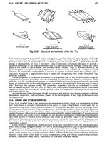
Nonmetallic
Gaskets. Most nonmetallic gaskets consist
of a fibrous
base held together with
some
form
of an
elastomeric binder.
A
gasket
is
formulated
to
provide
the
best load-bearing properties
while being compatible with
the fluid
being sealed.
Nonmetallic gaskets
are
often
reinforced
to
improve torque retention
and
blowout resistance
for
more severe service requirements. Some types
of
reinforcements include perforated cores, solid cores,
perforated
skins,
and
solid skins, each suited
for
specific
applications.
After
a
gasket material
has
been reinforced
by
either material additions
or
laminating, manufacturers
can
emboss
the
gasket
raising
a
sealing lip, which increases localized pressures, thereby increasing
scalability.
Metallic
Gaskets. Metallic gaskets
are
generally used where either
the
joint temperature
or
load
is
extreme
or in
applications where
the
joint might
be
exposed
to
particularly caustic chemicals.
A
good seal capable
of
withstanding very high temperature
is
possible
if the
joint
is
designed
to
yield
locally over
a
narrow location with application
of
bolt load. Some
of the
most common metallic
gaskets range
from
soft
varieties, such
as
copper, aluminum, brass,
and
nickel,
to
highly alloyed
steels.
Noble metals, such
as
platinum, silver,
and
gold,
also have been used
in
difficult
locations.
Metallic gaskets
are
available
in
both standard
and
custom designs. Since there
is
such
a
wide
variety
of
designs
and
materials used,
it is
recommended that
the
reader directly contact metallic
gasket suppliers
for
design
and
sealing information.
Required
Bolt
Load
ASME
Method.
The
ASME
Code
for
Pressure Vessels, Section
VIII,
Div.
1,
App.
2, is the
most
commonly used design method
for
gasketed joints where important joint properties, including
flange
thickness, bolt size
and
pattern,
are
specified. Because
of the
absence
of
leakage considerations,
it
Table
22.1 (Continued)
Gasket
Material
Flat metal, jacketed asbestos
filled:
Soft
aluminum
Soft
copper
or
brass
Iron
or
soft
steel
Monel
4%-6%
chrome
Stainless steels
and
nickel-base
alloys
Grooved metal:
Soft
aluminum
Soft
copper
or
brass
Iron
or
soft
steel
Monel
or
4%-6% chrome
Stainless steels
and
nickel-base
alloys
Solid
flat
metal:
Soft
aluminum
Soft
copper
or
brass
Iron
or
soft
steel
Monel
or
4%—
6%
chrome
Stainless steels
and
nickel-base
alloys
Ring
joint:
Iron
or
soft
steel
Monel
or
4%-6%
chrome
Stainless steels
and
nickel-base
alloys
Gasket
Factor
/77
3.25
3.50
3.75
3.50
3.75
3.75
3.25
3.50
3.75
3.75
4.25
4.00
4.75
5.50
6.00
6.50
5.50
6.00
6.50
Min.
Design
Seating
Stress
y,
psi
5500
6500
7600
8000
9000
9000
5500
6500
7600
9000
10,100
8800
13,000
18,000
21,800
26,000
18,000
21,800
26,000
Sketches
should
be
noted that
the
ASME
is
currently evaluating
the
Pressure Vessel Research Council's method
for
gasket design.
It is
likely that
a
nonmandatory
appendix
to the
Code will appear
first
(see dis-
cussion
in
Ref.
3).
An
integral part
of the
AMSE Code revolves around
two
gasket factors:
1. An m
factor,
often
called
the
gasket-maintenance factor,
is
associated with
the
hydrostatic
end
force
and the
operation
of the
joint.
2. The y
factor
is a
rough measure
of the
minimum seating stress associated with
a
particular
gasket
material.
The y
factor pertains only
to the
initial assembly
of the
joint.
The
ASME Code makes
use of two
basic equations
to
calculate bolt load, with
the
larger calculated
load
being used
for
design:
W
ml
= H +
H
p
= -
G
2
P
+
2TTbGmP
W
m2
=
H
y
=
TTbGy
where
W
ml
=
minimum required bolt load
from
maximum operating
or
working conditions,
Ib
W
m2
=
minimum required initial bolt load
for
gasket seating (atmospheric-temperature con-
ditions)
without internal pressure,
Ib
H
=
total hydrostatic
end
force,
Ib
[(TrM)G
2
P]
H
p
=
total
joint-contact-surface
compression load,
Ib
Hy
=
total
joint-contact-surface
seating load,
Ib
G
=
diameter
at
location
of
gasket load reaction; generally
defined
as
follows: When
b
0
<
1
A
in.,
G =
mean diameter
of
gasket contact face,
in.;
When
b
Q
>
14
in.,
G =
outside
diameter
of
gasket contact
face
less
2b,
in.
P
=
maximum internal design pressure,
psi
b =
effective
gasket
or
joint-contact-surface
seating width,
in.
b
=
b
0
when
b
0
^
1
A
in.
b =
0.5Vb
0
when
b
0
>
1
A
in.
2b
=
effective
gasket
or
joint-contact-surface
pressure width,
in.
b
Q
=
basic gasket seating width
per
ASME Table
2-5.2.
The
table
defines
b
0
in
terms
of
flange finish
and
type
of
gasket, usually
from
one-half
to
one-fourth gasket contact
width
m =
gasket
factor
per
ASME Table
2-5.1
(repeated here
as
Table
22.1).
y
=
gasket
or
joint-contact-surface
unit seating load,
per
ASME Table
2-5.1
(repeated here
as
Table
22.1),
psi
The
factor
m
provides
a
margin
of
safety
to be
applied when
the
hydrostatic
end
force becomes
a
determining
factor.
Unfortunately, this value
is
difficult
to
obtain experimentally since
it is not a
constant.
The
equation
for
W
m2
assumes that
a
certain unit stress
is
required
on a
gasket
to
make
it
conform
to the
sealing surfaces
and be
effective.
The
second empirical constant
y
represents
the
gasket
yield-stress value
and is
very
difficult
to
obtain experimentally.
Practical
Considerations
Flange
Surfaces.
Preparing
the flange
surfaces
is
paramount
for
effecting
a
good gasket seal.
Surface
finish
affects
the
degree
of
scalability.
The
rougher
the
surface,
the
more bolt load required
to
provide
an
adequate seal. Extremely smooth
finishes can
cause problems
for
high operating pres-
sures,
as
lower
frictional
resistance leads
to a
higher tendency
for
blowout. Surface
finish lay is
important
in
certain applications
to
mitigate leakage. Orienting
finish
marks transverse
to the
normal
leakage path will generally improve
scalability.
Flange
Thickness.
Flange thickness must also
be
sized correctly
to
transmit bolt clamping load
to
the
area between
the
bolts. Maintaining seal loads
at the
midpoint between
the
bolts must
be
kept
constantly
in
mind. Adequate thickness
is
also required
to
minimize
the
bowing
of the flange. If the
flange
is
too
thin,
the
bowing will become excessive
and no
bolt load will
be
carried
to the
midpoint,
preventing
sealing.
Bolt
Pattern. Bolt pattern
and
frequency
are
critical
in
effecting
a
good seal.
The
best bolt
clamping
pattern
is
invariably
a
combination
of the
maximum practical number
of
bolts, optimum
spacing,
and
positioning.
One can
envision
the
bolt loading pattern
as a
series
of
straight lines drawn
from
bolt
to
adjacent
bolt until
the
circuit
is
completed.
If the
sealing areas
lie on
either side
of
this pattern,
it
will likely
be a
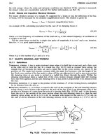
potential leakage location. Figure
22.1
shows
an
example
of the
various
conditions.
2
If
bolts
Fig.
22.1
Bolting pattern
indicating
poor sealing areas. (From Ref.
2.)
cannot
be
easily repositioned
on a
problematic
flange,
Fig. 22.2 illustrates techniques
to
improve
gasket effectiveness through reducing gasket
face
width where bolt load
is
minimum. Note that gasket
width
is
retained
in the
vicinity
of the
bolt
to
support local bolt loads
and
minimize gasket tearing.
Gasket
Thickness
and
Compressibility.
Gasket thickness
and
compressibility must
be
matched
to the
rigidity, roughness,
and
unevenness
of the
mating flanges.
An
effective gasket
seal
is
achieved
only
if the
stress level imposed
on the
gasket
at
installation
is
adequate
for the
specific gasket
and
joint
requirements.
Original
gasket: Redesigned gasket
gasket
identical
to
casting flange
Fig.
22.2
Original
vs.
redesigned gasket
for
improved sealing.
(From
Ref.
2.)
Gaskets made
of
compressible materials should
be as
thin
as
possible. Adequate gasket thickness
is
required
to
seal
and
conform
to the
unevenness
of the
mating
flanges,
including
surface
finish,
flange flatness,
and
flange
warpage
during use.
A
gasket that
is too
thick
can
compromise
the
seal
during
pressurization
cycles
and is
more likely
to
exhibit creep relaxation over time.
22.2.2
O-Rings
O-ring
seals
are
perhaps
one of the
most common
forms
of
seals. Following relatively straightforward
design
guidelines,
a
designer
can be
confident
of a
high-quality seal over
a
wide range
of
operating
conditions.
This
section provides
useful
insight
to
designers approaching
an
O-ring seal design,
including
basic sealing mechanism, preload, temperature
effects,
common materials,
and
chemical
compatibility with
a
range
of
working
fluids. The
reader
is
directed
to
manufacturer's design manuals
for
detailed information
on the final
selection
and
specification.
4
Basic
Sealing Mechanism
O-rings
are
compressed between
the two
mating
surfaces
and are
retained
in a
seal gland.
The
initial
compression provides
initial
sealing
critical
to
successful sealing. Upon
increase
of the
pressure
differential
across
the
seal,
the
seal
is
forced
to flow to the
lower pressure side
of the
gland (see Fig.
22.3).
As the
seal moves,
it
gains greater area
and
force
of
sealing contact.
At the
pressure limit
of
the
seal,
the
O-ring just begins
to
extrude into
the gap
between
the
inner
and
outer member
of the
gap.
If
this pressure limit
is
exceeded,
the
O-ring will
fail
by
extruding into
the
gap.
The
shear
strength
of the
seal material
is no
longer
sufficient
to
resist
flow and the
seal material extrudes
(flows)
out of the
open passage. Back-up
rings are
used
to
prevent seal extrusion
for
high-pressure static
and
for
dynamic applications.
Preload
The
tendency
of an
O-ring
to
return
to its
original shape
after
the
cross section
is
compressed
is the
basic reason
why
O-rings make such excellent
seals.
The
maximum linear compression suggested
by
manufacturers
is 30% for
static applications
and 16% for
dynamic seals
(up to 25% for
small cross-
sectional diameters). Compression less than these values
is
acceptable, within reason,
if
assembly
Fig.
22.3
Basic O-ring sealing
mechanism,
(a)
O-ring installed;
(b)
O-ring under pressure;
(c)
O-ring extruding;
(d)
O-ring failure. (From Ref.
4.)
problems
are an
issue. Manufacturers
recommend
4
a
minimum amount
of
initial linear compression
to
overcome compression
set
that
O-rings
exhibit.
O-ring
compression force depends principally
on the
hardness
of the
O-ring,
its
cross-sectional
dimension,
and the
amount
of
compression. Figure 22.4 illustrates
the
range
of
compressive
force
per
linear inch
of
seal
for
typical linear percent compressions
(0.139
in.
cross-section diameter)
and
compound hardness (Shore
A
hardness scale).
Softer
compounds provide better sealing ability,
as the
rubber
flows
more easily into
the
grooves. Harder compounds
are
specified
for
high pressures,
to
limit chance
of
extruding into
the
groove,
and to
improve wear
life
for
dynamic service.
For
most
applications, compounds having
a
Type
A
durometer hardness
from
70-80
are the
most suitable
compromise.
4
Thermal Effects
O-ring seals respond
to
temperature changes. Therefore,
it is
critical
to
ensure
the
correct material
and
hardness
is
selected
for the
application. High temperatures
soften
compounds. This
softening
can
negatively
affect
the
seal's
extrusion resistance
at
temperature. Over long periods
of
time
at
high
temperature, chemical changes occur. These generally cause
an
increase
in
hardness, along with
volume
and
compression-set changes.
O-ring compounds harden
and
contract
at
cold temperatures. These
effects
can
both lead
to a
loss
of
seal
if
initial compression
is not set
properly. Because
the
compound
is
harder,
it
does
not flow
into
the
mating surface irregularities
as
well. Just
as
important,
the
more common O-ring materials
have
a
coefficient
of
thermal expansion
10
times greater than that
of
steel (i.e.,
nitrile
CTE is 6.2 X
10-
50
F).
Groove dimensions must
be
sized correctly
to
account
for
this dimensional change. Manufacturers
design
charts
4
are
devised such that proper O-ring sealing
is
ensured
for the
temperature ranges
for
standard
elastomeric
materials. However,
the
designer
may
want
to
modify
gland dimensions
for a
given
application that experiences only high
or low
temperatures
in
order
to
maintain
a
particular
squeeze
on the
O-ring.
Martini
5
gives several practical examples showing
how to
tailor
groove
di-
mensions
to
maintain
a
given
squeeze
for the
operating temperature.
Material
Selection/Chemical
Compatibility
Seal compounds must work properly over
the
required temperature range, have
the
proper hardness
to
resist extrusion while
effectively
sealing,
and
must also resist chemical attack
and
resultant swelling
caused
by the
operating
fluids.
Table 22.2 summarizes
the
most important elastomers, their working
temperature range,
and
their resistance
to a
range
of
common working
fluids.
Rotary
Applications
O-rings
are
also
used
to
seal
rotary
shafts
where surface
speeds
and
pressures
are
relatively low.
One
factor
that must
be
carefully
considered when applying O-ring seals
to
rotary applications
is the
Gow-
Fig.
22.4
Effect
of
percent compression
and
material Shore hardness
on
seal compression
load,
0.139-in.
cross section. (From Ref.
4.)
Note:
x,
stable;
o,
stable
under
certain conditions;
—
,
unstable.
Natural rubber
S.B.R.
Nitrile
N
Neoprene
Butyl
Hypalon
Silicone
rubber
Thiokol
Polyacrylic
Vulcollan
Adiprene
KeI-F
Viton
PTFE
E.P.R.
F.S.R.
Rubber,
K. W.
Coil
Refining-type
polymerisate
Butadiene-styrene
copolymer
Butadiene-acrylonitrile
copolymer
Chlorinated-butadiene
polymerisate
Isobutylene-isoprene
copolymer
Chloro-sulfonated
polyethylene
Polycondensates
of
dialkylsiloxanes
Alkylopolysulfide
Polyacrylate
Polyurethane
Polyurethane
Copolymer
of
chlorotriethylene
and
vinylidene
fluoride
Vinylidene
fluoride-
hexafluoropropylene
copolymer
Polytetrafluoroethylene
Ethylene-propylene
Fluoro-silicone
rubber
-30 to 120
-30 to 130
-30 to 130
-40 to 140
-50 to 150
-40 to 140
-100
to 200
-40 to 80
-30 to 120
-30 to 80
-40 to 120
-50 to 180
-60 to 200
-200
to 280
-55 to 200
-60 to 230
50 to 280
50 to 240
50 to 240
50 to 270
40 to 170
40 to 200
20
to 80
10
to 60
20
to 70
200 to 320
80
to 300
30 to 120
80
to 160
140 to 310
50 to 160
55 to 85
1000
700
700
800
900
600
500
200
700
600
700
700
300
200
400
400
30
to 98
40 to 95
40 to 95
40
to 95
40
to 90
40 to 95
40 to 80
65
to 80
70 to 85
70 to 95
70
to 95
60 to 90
60 to 95
55D
70 to 95
40 to 80
X
X
X
X— 0
X
O X
X
X
—
O
X
X
X
O X X X
XO — X X OXO
X
—
O
OOX
XX
O
O XO
X
—
XOXXX
XX O
O
X
O
XOOXOXXX
XO
O
X
X
XOXXX
O
O
X XO —
XO
XOXOO
X
X
X X
XXOOXOXXOXXX
O
X
X X
XXOOO
X
O O
O
X
X X X —
O
XO
X
X
XX
—
O
—
XX
O
XO
X
XXXXX
XO O X X
XXXOX
XOO
X
XX X X X
XXXXXXXXXXXX
XX X
X
XXOXOXXX
OO O X X
XXXOX
OO
XOX
Table
22.2
The
Most Important Elastomers
and
Their
Properties
1
Elastomer
Composition
Working temperature
range,
0
C
Tensile strength,
bar
Elongation,
%
Hardness, °Shore
Water
Steam
Hydraulic fluids, non-
flammable (ester-based)
Mineral fats
and
oils
Vegetable
and
animal
fats
and
oils
Ozone
Aliphatic
Aromatic
Hydrocarbons
Halogenated
Alcohols
Ketones
Esters
Dilute acids
Concentrated acids
Dilute alkalis
Concentrated alkalis
Saline solutions
Joule
effect.
5
When
a
rubber
O-ring
is
stretched slightly around
a
rotating
shaft,
(e.g.
put in
tension)
friction
between
the
ring
and
shaft
generates heat causing
the
ring
to
contract, exhibiting
a
negative
expansion
coefficient.
As the
ring contracts
friction
forces increase generating additional heat
and
further
contraction. This positive-feedback cycle causes rapid seal failures. Similar
failures
in
recip-
rocating applications
and
static applications
are
unusual because
surface
speeds
are too low to
initiate
the
cycle. Further,
in
reciprocating applications
the
seal
is
moved into contact with cooler
adjacent
material.
To
prevent
the
failure
cycle,
O-rings
are not
stretched over
shafts
but are
oversized slightly
(circumferentially)
and
compressed into
the
sealing groove.
The
pre-compression
of the
cross-section
results
in
O-ring stresses that oppose
the
contraction stress preventing
the
failure
cycle described.
Martini
5
provides guidelines
for
specifying
the
O-ring seal. Following appropriate techniques O-ring
seals have
run for
significant
periods
of
time
at
speeds
up to 750 fpm and
pressures
up to 200
psi.
22.2.3
Packings
and
Braided Rope Seals
Rope packings used
to
seal
stuffing
boxes
and
valves
and
prevent excessive leakage
can be
traced
back
to the
early days
of the
Industrial Revolution.
An
excellent summary
of
types
of
rope seal
packings
is
given
in
Ref.
6.
Novel adaptations
of
these seal packings have been required
as
temper-
atures have continued
to rise to
meet modern system requirements.
New
ceramic materials
are
being
investigated
to
replace asbestos
in a
variety
of
gasket
and
rope-packing constructions.
Materials
Packing materials
are
selected
for
intended-temperature
and
chemical environment. Graphite-based
packing/gaskets
are
rated
for up to
100O
0
F
for
oxidizing environments
and up to
540O
0
F
for
reducing
environments.
7
Used within
its
recommended temperature, graphite will provide
a
good seal with
acceptable ability
to
track joint movement during
temperature/pressure
excursions. Graphite
can be
laminated with itself
to
increase thickness
or
with
metal/plastic
to
improve handling
and
mechanical
strength. Table 22.2 provides working temperatures
for
conventional (e.g.,
nitrile,
PTFE,
neoprene,
amongst
others) gasket/packings. Table 22.3 provides typical maximum working temperatures
for
high temperature
gasket/packing
materials.
Packings
and
Braided Rope Seals
for
High-Temperature Service
High-temperature packings
and
rope seals
are
required
for a
variety
of
applications, including sealing:
furnace
joints, locations within continuous casting units (gate seals, mold seals, runners, spouts, etc.),
amongst others. High-temperature packings
are
used
for
numerous aerospace applications, including
turbine casing
and
turbine engine locations, Space Shuttle thermal protection systems,
and
nozzle
joint seals.
Aircraft
engine turbine inlet temperatures
and
industrial system temperatures continue
to
climb
to
meet aggressive cycle thermal
efficiency
goals. Advanced material systems, including monolithic/
composite ceramics,
intermetallic
alloys (i.e., nickel
aluminide),
and
carbon-carbon
composites,
are
Table
22.3
Gasket/Rope
Seal Materials
Maximum
Working
Temperature
Fiber
Material
0
F
Graphite
Oxidizing environment 1000
Reducing
5400
Fiberglass (glass dependent) 1000
Superalloy metals
(depending
on
alloy)
1300-1600
Oxide Ceramics (Ref.
Tompkins
1995)*
62%
Al
2
O
3
24%
SiO
2
14%
B
2
O
3
180Of
(Nextel
312)
70%
Al
2
O
3
28%
SiO
2
2%
B
2
O
3
200Of
(Nextel 440)
73%
Al
2
O
3
27%
SiO
2
(Nextel 550)
210Of
*Tompkins,
T. L.
"Ceramic
Oxide
Fibers:
Building Blocks
for
New
Applications," Ceramic Industry
Publ,
Business
News
Publishing, April, 1995.
tTemperature
at
which
fiber
retains
50%
(nominal) room
temperature strength.
being
explored
to
meet aggressive temperature, durability,
and
weight requirements. Incorporating
these
materials
in the
high-temperature locations
in the
system, designers must overcome materials
issues, such
as
differences
in
thermal expansion rates
and
lack
of
material ductility.
Designers
are
finding
that
one way to
avoid cracking
and
buckling
of the
high-temperature brittle
components
rigidly
mounted
in
their support structures
is to
allow relative motion between
the
pri-
mary
and
supporting
components.
8
Often
this joint occurs
in a
location where differential pressures
exist, requiring high-temperature seals. These seals
or
packings must exhibit
the
following important
properties: operate
hot
(>1300°F);
exhibit
low
leakage; resist mechanical scrubbing caused
by
dif-
ferential
thermal growth
and
acoustic loads; seal complex geometries; retain
resilience
after
cycling;
and
support structural loads.
In
an
industrial seal application,
a
high-temperature all-ceramic seal
is
being used
to
seal
the
interface
between
a
low-expansion rate primary structure
and the
surrounding support structure.
The
seal consists
of a
dense uniaxial
fiber
core overbraided with
two
two-dimensional braided sheath
layers.
8
Both core
and
sheath
are
composed
of 8
/urn
alumina-silica
fibers
(Nextel 550) capable
of
withstanding
2000+
0
F
temperatures.
In
this application over
a
heat/cool
cycle,
the
support structure
moves
0.3 in.
relative
to the
primary structure, precluding normal
fixed-attachment
techniques. Leak-
age flows for the
all-ceramic seal
are
shown
in
Fig. 22.5
for
three temperatures
after
simulated
scrubbing
8
(10
cycles
X
0.3-in.
at
130O
0
F).
In
a
turbine vane application,
the
conventional braze joint
is
replaced with
a floating
seal arrange-
ment
incorporating
a
small-diameter
(
!
/i6-in.)
rope seal (Fig. 22.6).
The
seal
is
designed
to
serve
as
a
seal
and a
compliant mount, allowing relative thermal growth between
the
high-temperature turbine
vane
and the
lower-temperature support structure, preventing thermal strains
and
stresses.
A
hybrid
seal consisting
of a
dense uniaxial ceramic core
(8
/xrn
alumina-silica
Nextel
550 fibers)
overbraided
with
a
superalloy wire
(0.0016-in.
diameter Haynes
188
alloy) abrasion-resistant sheath
has
proven
successful
for
this
application.
9
Leakage
flows for the
hybrid seal
are
shown
in
Fig. 22.7
for two
temperatures,
and
pressures under
two
preload conditions
after
simulated scrubbing
(10
cycles
X
0.3-
in. at
130O
0
F).
Recent
studies
8
have shown
the
benefits
of
high sheath braid angle
and
double-stage seals
for
reducing
leakage. Increasing hybrid seal sheath braid angle
and
increasing core coverage
led to
increased compressive
force
(for
the
same linear seal compression)
and
one-third
the
leakage
of the
conventional
hybrid design. Adding
a
second seal stage reduced seal leakage
30%
relative
to a
single
stage.
22.3
DYNAMICSEALS
22.3.1
Initial
Seal Selection
An
engineer approaching
a
dynamic seal design
has a
wide range
of
seals
to
choose
from.
A
partial
list
of
seals available ranges
from
the
mechanical
face
seal through
the
labyrinth
and
brush seal,
as
Fig.
22.5
Flow
vs.
pressure data
for 3
temperatures,
Vie
in.
diameter all-ceramic seal, 0.022
in.
seal
compression, after
scrubbing.
(From Ref.
8.)
Fig.
22.6
Schematic
of
turbine vane seal. (From Ref.
9.)
indicated
in
Fig. 22.8.
To aid in the
initial seal selection,
a
"decision
tree"
has
been proposed
by
Fern
and
Nau.
10
The
decision tree (see Fig. 22.9)
has
been updated
for the
current work
to
account
for
the
emergence
of
brush
seals.
In
this chart,
a
majority
of
answers either "yes"
or
"no"
to the
questions
at
each stage leads
the
designer
to an
appropriate seal starting point.
If
answers
are
equally
divided, both alternatives should
be
explored using other design criteria, such
as
performance, size,
and
cost.
The
scope
of
this chapter does
not
permit treatment
of
every entry
in the
decision tree. However,
several examples
are
given below
to aid in
understanding
its
use.
Radial
lip
seals
are
used
to
prevent
fluids,
normally lubricated,
from
leaking around
shafts
and
their housings. They
are
also used
to
prevent dust, dirt,
and
foreign contaminants
from
entering
the
Fig.
22.7
The
effect
of
temperature,
pressure,
and
representative compression
on
seal flow
af-
ter
cycling
for
0.060-in.
hybrid vane seal. (From Ref.
9.)
Fig.
22.8
Examples
of the
main types
of
rotary
seal,
(a)
Mechanical face seal;
(b)
Stuffing
box;
(c)
Lip
seal;
(of)
Fixed bushing;
(e)
Floating
bushing;
(f)
Labyrinth;
(g)
Viscoseal;
(h)
Hydrostatic
seal;
(/)
Brush seal.
((a)-(h)
From Ref.
10.)
lubricant
chamber. Depending
on
conditions,
lip
seals have been designed
to
operate
at
very high
shaft
speeds
(6,000-12,000
rpm)
with light
oil
mist
and no
pressure
in a
clean environment.
Lip
seals have replaced mechanical
face
seals
in
automotive water pumps
at
pressures
to 30
psi, tem-
peratures
-45
0
F
to
35O
0
F,
and
shaft
speeds
to
8000
sfpm
(American
Variseal,
1994).
Lip
seals
are
also
used
in
completely
flooded
low-speed applications
or in
muddy environments.
A
major
advantage
of
the
radial
lip
seal
is its
compactness.
A
0.32-in.
by
0.32-in.
lip
seal provides
a
very good seal
for
a
2-in. diameter
shaft.
Mechanical
face
seals
are
capable
of
handling much higher pressures
and a
wider range
of fluids.
Mechanical
face
seals
are
recommended over brush
seals
where
very
high pressures must
be
sealed
rr;
Stuffing
box
Is
initial
cost
critical
?
I
Is
fitting
or
maintenance
by
I
unskilled labor
?
1
Yes
I
I
Mechanical
face
T
1
A
seal
Is
seal pressure over
15
psid
? T
No
Yes
Is
it
required
to
seal
fluids
other
N
0
\
f
than
oil?
'
Yes
Is it
required
to
operate
at
Are
Ion
9
"f*
and low
wear essential
?
temperatures over
300
0
F
?
ls
ver
Y
low
leakage required
?
Is
a
relatively
high
initial
cost
Do
Sealin
9
f
a°es
remain true
to one
acceptable
?
another
?
Are
pressures
>
120
psid
on
single stage
?
i
L Is
shaft rotation bi-directional
?
'
^
Brush seal
(No
flammable media)
"NO
Start
l
Lip
seal
L
Is
commercial
availability
required
?
Is
very
low
leakage essential
?
Is
precision alignment possible?
Is
finite
life acceptable
?
I
I
Fixed bushing
lNo
I
Yes
'
Is
high leakage acceptable
?
Is
simplicity
of
design important
?
Is
precision alignment possible
?
k
i
Hydrostatic
lYes
seal
T
Is
zero leakage
at
rest essential
?
Can
very
complex design
be
tolerated
?
na
Viscoseal
\
0
t
Is
zero leakage when
running essential
?
Is
simplicity
of
manufacture
important
?
r—
Floating
i
Yes
bushing
No
T
'
• Is low
leakage required
?
Is
small running clearance
acceptable
?
T
No
'
Labyrinth
Fig.
22.9
Seal selection chart
(a
majority answer
of
"yes"
or
"no"
to the
question
at
each
stage leads
the
reader
to the
appropriate decision;
if
answers
are
equally divided both alterna-
tives should
be
explored).
(Adaptejd
from
Ref.
10.)
in
a
single stage. Mechanical
face
seals have
a
lower
leakag^
than brush seals because their
effective
clearances
are
several times smaller. However,
the
mechanical
face
seal requires much better control
of
dimensions
and
tolerates less
shaft
misalignment
and
runout, thereby increasing costs.
Turbine
Engine Seals. Readers interested particularly
in
turbine engine seals
are
referred
to
Steinetz
and
Hendricks,
11
(1997) which reviews
in
greater depth
the
tradeoffs
in
selecting seals
for
turbine
engine applications. Technical factors increasing seal design complexity
for
aircraft
engines
include
high temperatures
(2:100O
0
F),
high
surface
speeds
(up to
1500 fps), rapid
thermal/structural
transients,
maneuver
and
landing loads,
and the
requirement
to be
lightweight.
22.3.2
Mechanical
Face
Seals
The
primary elements
of a
conventional spring-loaded mechanical
face
seal
are the
primary seal (the
main
sealing
faces),
the
secondary seal (seals
shaft
leakage),
and the
spring
or
bellows element that
keep
the
primary seal surfaces
in
contact, shown
in
Fig. 22.8.
The
primary seal
faces
are
generally
lapped
to
demanding surface
flatness,
with surface
flatness of 40
/xin
(1
micron)
not
uncommon.
Surface
flatness
this
low is
required
to
make
a
good seal, since
the
running clearances
are
small.
Conventional mechanical
face
seals operate with clearances
of
40-200
/xin.
Dry-running, noncon-
tacting
gas
face
seals that
use
spiral groove
face
geometry reliably
run at
pressures
of
1800
psig
and
speeds
up to 590 fps
(John Crane, 1993).
Seal
Balance
Seal balancing
is a
technique whereby
the
primary
seal
front
and
rear areas
are
used
to
minimize
the
contact
pressure between
the
mating seal
faces
to
reduce wear
and to
increase
the
operating pressure
capability.
The
concept
of
seal balancing
is
illustrated
in
Fig.
22.10.
12
The
front
and
rear faces
of
the
seal
in
Fig.
22.1Oa
are
identical
and the
full
fluid
pressure exerted
on
A'
is
carried
on the
seal
face
A. By
modifying
the
geometry
of the
primary seal head
ring to
establish
a
smaller
frontal
area
A'
(Fig.
22.Wb)
and to
provide
a
shoulder
on the
opposite side
of the
seal
ring to
form
a
front
face
B',
the
hydraulic pressure counteracts part
of the
hydraulic loading
from
A'.
Consequently,
the
remaining
face
pressure
in the
contact interface
is
significantly
reduced. Depending
on the
relative
sizes
of
surfaces
A'
and
B',
the
seal
is
either partially balanced (Fig.
22.Wb)
or
fully
balanced (Fig.
22.1Oc).
In
fully
balanced seals, there
is no net
hydraulic load exerted
on the
seal face. Seals
are
Fig.
22.10
Illustration
of
face
seal
balance
conditions,
(a)
Unbalanced;
(jb)
Partially
balanced;
(c)
Fully
balanced.
(From
Ref.
12.)
generally
run
with
a
partial balance, however,
to
minimize
face
loads
and
wear while keeping
the
seal closed during possible transient overpressure conditions. Partially balanced seals
can run at
pressures greater than
six
times unbalanced seals
can for the
same speed
and
temperature conditions.
Mechanical
Face Seal Leakage
Liquid Flow. Minimizing leakage between seal faces
is
possible only through maintaining small
clearances. Volumetric
flow (Q) can be
determined
for the
following
two
conditions (Lebeck,
1991).
13
For
Coned
Faces:
^r
m
I
P
0
-P
1
\
*
3/i
\\lhl
-
1/%)
For
Parallel
Faces:
Q
=
~^
mh3
(P
°
~
P
^
h
0
=
h
t
and
((r
0
-
r
t
)/r
m
<
0.1)
6{Ji
(r
0
-
r
f
)
where
4>
(radians)
is the
cone angle (positive
if
faces
are
convergent travelling inward radially);
r
0
,
r
t
(in.) outer
and
inner radii;
r
m
(in.) mean radius
(in.);
H
0
,
h
t
(in.) outer
and
inner
film
thicknesses;
P
0
,
P
1
(psi) outer
and
inner pressures;
IJL
(M •
s/in.
2
)
viscosity.
The
need
for
small clearances
is
demonstrated
by
noting that doubling
the film
clearance,
h,
increases
the
leakage
flow
eight-fold.
Gas
Flow.
Closed-form equations
for gas flow
through parallel faces
can be
written only
for
conditions
of
laminar
flow
(Reynolds
No. <
2300).
For
laminar
flow
with
a
parabolic pressure
distribution across
the
seal faces,
the
mass
flow is
given
as
(Lebeck,
1991):
13
•*-F^7
LJ
?
(' '•>"-«»
12jjiRT
(r
0
-
r
z
)
where
R is the gas
constant (53.3
lbf
•
ft/lb
m
•
0
R
for
air),
and T
(
0
R)
is the gas
temperature (isothermal
throughout).
In
cases where
flow is
both laminar
and
turbulent, iterative schemes must
be
employed.
See
Refs.
13
and 14 for
numerical algorithms
to use in
solving
for the
seal leakage rates. Reference
15
treats
the
most general case
of
two-phase
flow
through
the
seal faces.
Seal Face Flatness
In
addition
to
lapping
faces
to the 40
/nn.
flatness,
there
are
several other points
to
consider.
The
lapped
rings
should
be
mounted
on
surfaces that
are
themselves
flat. The ring
must
be
stiff
enough
to
resist distortions caused either
by
thermal
or fluid
pressure stresses.
The
primary mode
of
distortion
of a
mechanical seal
face
under combined
fluid and
thermal
stresses
is
solid body rotation about
the
seal's
neutral
axis.
10
If the sum of the
moments
M
(in lb/
in.)
per
unit
of
circumference around
the
neutral axis
can be
calculated, then
the
angular
deflection
6
(radians)
of the
sealing
face,
can be
obtained
from
O
=
Mr
2
JEI
where
E
(psi)
=
Young's modulus
7
(in.
4
)
= the
second moment
of
areas about
the
neutral axis
r
m
(in.)
= the
mean radius
of the
seal
ring
Face Seal
Materials
Selecting
the
correct materials
for a
given seal application
is
critical
to
ensuring desired performance
and
durability. Seal components
for
which material selection
is
important
from
a
tribology
standpoint
are
the
stationary nosepiece
(or
primary seal
ring) and the
mating
ring (or
seal seat). Properties
considered ideal
for the
primary seal ring
are
shown
below.
16
1.
Mechanical:
(a)
High modulus
of
elasticity
(b)
High
tensile
strength
(c) Low
coefficient
of
friction
(d)
Excellent wear characteristics
and
hardness
(e)
Self-lubrication
2.
Thermal:
(a) Low
coefficient
of
expansion
(b)
High thermal conductivity
(c)
Thermal shock resistance
(d)
Thermal stability
3.
Chemical:
(a)
Corrosion resistance
(b)
Good wetability
4.
Miscellaneous:
(a)
Dimensional stability
(b)
Good machinability
and
ease
of
manufacture
(c) Low
cost
and
ready availability
Carbon-graphite
is
often
the first
choice
for one of the
running seal surfaces because
of its
superior
dry-running
(i.e., start-up) behavior.
It can run
against itself, metals,
or
ceramics without galling
or
seizing.
Carbon-graphite
is
generally impregnated with resin
or
with
a
metal
to
increase thermal
conductivity
and
bearing characteristics.
In
cases where
the
seal will
see
considerable abrasives,
carbon
may
wear excessively
and
then
it is
desirable
to
select very hard seal-face materials.
A
preferred
combination
for
very long wear (subject
to
other constraints)
is
tungsten carbide running
on
tungsten carbide.
For a
comprehensive coverage
of
face
seal material selection, including chemical
compatibility,
see
Ref.
17.
Secondary seals
are
either
O-rings
or
bellows. Temperature ranges
and
chemical compatibility
for
common O-ring secondary seals such
as
nitrile,
fluorocarbon
(Viton),
and
PTFE
(Teflon)
are
provided
in
Table 22.2.
22.3.3
Emission Concerns
Mechanical
face
seals have played
and
will continue
to
play
a
major
role
for
many years
in
mini-
mizing
emissions
to the
atmosphere.
New
federal, state,
and
local environmental regulations have
intensified
the
focus
on
mechanical
face
seal performance
in
terms
of
emissions. Within
a
short time,
regulators have gone
from
little
or no
concern about
fugitive
hazardous emissions
to a
position
of
severely restricting
all
hazardous emissions.
For
instance, under
the
authority
of
Title
III of the
1990
Clean
Air Act
Amendment (CAAA),
the
U.S. Environmental Protection Agency (EPA) adopted
the
National
Emission Standards
for
Hazardous
Air
Pollutants (NESHAP)
for the
control
of
emissions
of
volatile hazardous
air
pollutants (Ref. STLE,
1994).
18
Leak
definition
per the
regulation (EPA
HON
Subpart
H
(5))
are
defined
as
follows:
Phase
I:
10,000
parts
per
million volumetric
(ppmv),
beginning
on
compliance date
Phase
II:
5000
ppmv,
1
year
after
compliance date
Phase III:
1000-5000
ppmv, depending
on
application,
2
!/2
years
after
compliance date
The
Clean
Air Act
regulations require U.S.
plants
to
reduce emissions
of 189
hazardous
air
pollutants
by 80% in the
next several
years.
19
The
American Petroleum Industry (API)
has
responded
with
a
standard
of its
own, known
as API
682, that seeks
to
reduce maintenance costs
and
control
volatile organic compounds (VOC) emissions
on
centrifugal
and
rotary pumps
in
heavy service.
API
682,
a
pump
shaft
sealing standard,
is
designed
to
help
refinery
pump operators
and
similar users
comply
with environmental emissions regulations. These regulations will continue
to
have
a
major
impact
on
users
of
valves, pumps, compressors
and
other processing devices.
Seal
users
are
cautioned
to
check with their state
and
local
air
quality control authorities
for
specific
information.
Sealing Approaches
for
Emissions Controls
The
Society
of
Tribologists
and
Lubrication Engineers published
a
guideline
of
mechanical seals
for
meeting
the
fugitive
emissions
requirements.
18
Seal technology available meets approximately
95%
of
current
and
anticipated federal, state,
and
local
emission regulations. Applications
not
falling
within
the
guidelines include
food,
pharmaceutical,
and
monomer-type products where dual seals cannot
be
used
because
of
product purity requirements
and
chemical reaction
of
dual seal
buffer
fluids
with
the
sealed product.
Three sealing approaches
for
meeting
the new
regulatory requirements
are
discussed below: single
seals, tandem seals,
and
double
seals.
18
Single Seals.
The
most economical approach available
is the
single seal mounted inside
a
stuff-
ing
box
(Fig.
22.11).
Generally, this type
of
seal uses
the
pumped product
for
lubrication.
Due to
some
finite
clearance between
the
faces, there
is a
small amount
of
leakage
to
atmosphere. Using
current
technology
in the
design
of a
single seal, emissions
can be
controlled
to 500
ppm
based
on
Fig. 22.11 Single seal. (From Ref.
18.)
both laboratory
and field
test data. Emission
to
atmosphere
can be
eliminated
by
venting
the
atmos-
pheric side
to a
vapor recovery
or
disposal system. Using this approach, emissions readings
ap-
proaching zero
can be
achieved. Since single seals have
a
minimum
of
contacting parts
and
normally
require minimum support systems, they
are
considered highly reliable.
Tandem
Seals. Tandem seals consist
of two
seal assemblies between which
a
barrier
fluid op-
erates
at a
pressure less than
the
pumped process pressure.
The
inboard primary seal seals
the
full
pumped
product pressure,
and the
outboard seal typically seals
a
nonpressurized
barrier
fluid
(Fig.
22.12).
Tandem seal system designs
are
available that provide zero emission
of the
pumped product
to
the
environment, provided
the
vapor pressure
of the
product
is
higher
than
that
of the
barrier
fluid
and
the
product
is
immiscible
in the
barrier
fluid. The
barrier
fluid
isolates
the
pumped product
from
the
atmosphere
and is
maintained
by a
support system. This supply system generally includes
a
supply
tank assembly
and
optional cooling system
and
means
for
drawing
off the
volatile component
(generally
at the top of the
supply tank). Examples
of
common barrier
fluids are
found
in
Table 22.4.
Tandem
seal systems also provide
a
high level
of
sealing
and
reliability,
and are
simple systems
to
maintain,
due to the
typical
use of
nonpressurized barrier
fluid.
Pumped product contamination
by
the
barrier
fluid is
avoided since
the
barrier
fluid is at a
lower pressure than
the
pumped product.
Double
Seals. Double seals
differ
from
tandem seals
in
that
the
barrier
fluid
between
the
primary
and
outboard seal
is
pressurized (Fig. 22.13). Double seals
can be
either externally
or
internally
pressurized.
An
externally pressurized system requires
a
lubrication unit
to
pressurize
the
barrier
fluid
above
the
pumped product pressure
and to
provide cooling.
An
internally pressurized double seal
refers
to a
system that internally pressurizes
the fluid film at the
inboard
faces
as the
shaft
rotates.
In
this case,
the
barrier
fluid in the
seal chamber
is
normally
at
atmospheric pressure. This results
in
less
heat generation
from
the
system.
Application
Guide.
The
areas
of
application based
on
emissions
to
atmosphere
for the
three
types
of
seals discussed
are
illustrated
in
Fig. 22.14.
The
scope
of
this chart
is for
seals less than
6
in. in
diameter,
for
pressures
600
psig
and
less,
and for
surface
speeds
up to
5600
fpm.
Waterbury
19
FIg.
22.12 Tandem seal. (From Ref.
18.)
Table
22.4
Properties
of
Common Barrier Fluids
for
Tandem
or
Double
Seals
3
Temperature
Limits
0
F
Barrier Fluid Lower Upper Comments
Water
40 180 Use
corrosion-resistant materials
Protect
from
freezing
Propylene glycol
-76 368
Consult seal manufacturer
for
proper mixture with water
to
avoid excessive viscosity
n-Propyl
alcohol
-147
157
ATF
55 200
Contains additives
Kerosene
O 300
No.
2
diesel
fuel
10 300
Contains additives
"STLE
Society
of
Tribologists
and
Lubrication Engineers,
"Guidelines
for
Meeting
Emission Regulations
for
Rotating Machinery with Mechanical
Seals,"
Special Pub-
lication
SP-30,
1990.
provides
a
modern overview
of
several commercial products aimed
at
achieving zero
leakage
or
leak-
free
operation
in
compliance with current regulations.
22.3.4
Noncontacting Seals
for
High-Speed/Aerospace Applications
For
very high-speed
turbomachinery,
including
gas
turbines, seal runner speeds
may
reach speeds
greater than 1300 fps, requiring novel seal arrangements
to
overcome wear
and
pressure limitations
of
conventional face seals.
Two
classes
of
seals
are
used that rely
on a
thin
film of air to
separate
the
seal faces. Hydrostatic
face
seals port high pressure
fluid to the
sealing
face
to
induce opening
force
and
maintain controlled
face
separation (see Fig.
22.15).
The fluid
pressure developed between
the
faces
is
dependent upon
the gap
dimension
and the
pressure varies between
the
lower
and
upper
limits shown
in the figure. Any
change
in the
design clearance results
in an
increase
or
decrease
of
the
opening
force
in a
stabilizing sense.
Of the
four
configurations shown,
the
coned seal configuration
is
the
most popular. Converging
faces
are
used
to
provide seal stability. Hydrostatic
face
seals
suffer
from
contact during startup.
To
overcome this,
the
seals
can be
externally pressurized,
but
this adds
cost
and
complexity.
The
aspirating hydrostatic
face
seal (Fig.
22.l5d)
under development
by GE and
Stein Seal
for
turbine
engine applications provides
a
unique
failsafe
feature.
20
"
22
The
seal
is
designed
to be
open
during initial rotation
and
after
system
shutdown—the
two
periods during which potentially damaging
rubs
are
most common. Upon system
pressurization,
the
aspirating teeth
set up an
initial pressure
drop across
the
seal
(6 psi
nominal) that generates
a
closing force
to
overcome
the
retraction spring
force
F
s
causing
the
seal
to
close
to its
operating clearance (nominal
0.0015-0.0025
in.).
System
pressure
is
ported
to the
face
seal
to
prevent touchdown
and
provide good
film
stiffness
during
Fig. 22.13 Double seal. (From Ref.
18.)
Target control level,
ppmv,
Instrument
reading
Chart area Recommended technology
1
General purpose single seals,
or
dual
(double
and
tandem) seals
2
Special purpose single seals,
or
dual
(double
and
tandem)
seals
Dual pressurized (double) seals
Single
or
dual non-pressurized (tandem)
3
seals vented
to a
closed
vent
system,
above
0.4
specific gravity
Fig. 22.14 Application guide
to
control emissions. (From Ref.
18.)
operation.
At
engine shutdown,
the
pressure across
the
seal drops
and the
springs retract
the
seal
away
from
the
rotor, preventing contact.
Hydrodynamic
or
self-acting
face
seals incorporate
lift
pockets
to
generate
a
hydrodynamic
film
between
the two
faces
to
prevent seal contact.
A
number
of
lift
pocket configurations
are
employed,
including
shrouded
Rayleigh
step, spiral groove, circular groove,
and
annular groove (Fig.
22.16).
In
these designs, hydrodynamic
lift
is
independent
of the
seal pressure;
it is
proportional
to the
rotation
speed
and to the fluid
viscosity. Therefore
a
minimum speed
is
required
to
develop
sufficient lift
force
for
face
separation. Hydrodynamic seals operate
on
small
(<0.0005
in.
nominal) clearances,
resulting
in
very
low
leakage compared
to
labyrinth
or
brush seals,
as
shown
in
Fig.
22.17.
23
Because
rubbing occurs during startup
and
shutdown, seal
face
materials must
be
selected
for
good rubbing
characteristics
for low
wear (see Face Seal Materials, above).
Computer
Analysis
Tools:
Face/Annular
Seals
To
aid
aerospace
and
industrial seal designers alike, NASA sponsored
the
development
of
computer
codes
to
predict
the
seal performance under
a
variety
of
conditions.
24
Codes were developed
to
treat
both incompressible (e.g., liquid)
and
compressible (e.g., gas)
flow
conditions.
In
general,
the
codes
assess seal performance characteristics, including load capacity, leakage
flow,
power requirements,
Size:
Less
than
152
mm
(Q
in.) diameter
Pressure:
Less
than
40 bar
(600 psig)
Speed: Less than
28
m/sec
(5600 fpm) surface
Fig.
22.15 Self-energized hydrostatic noncontacting mechanical face
seals,
(a)
recessed pads
with orifice compensation;
(b)
recessed step;
(c)
convergent tapered face;
(d)
aspirating seal.
((a)-(c)
from Ref.
1;
(d)
from
Ref.
20.)
Fig. 22.16 Various types
of
hydrodynamic noncontacting mechanical face
seals,
(a)
Shrouded
Rayleigh
step;
(b)
Spiral groove;
(c)
Circular groove;
(d)
Annular groove. (From Ref.
1.)
and
dynamic characteristics
in the
form
of
stiffness
and
damping
coefficients.
These performance
characteristics
are
computed
as
functions
of
seal
and
groove geometry, loads
or film
thicknesses,
running
speed,
fluid
viscosity,
and
boundary pressures.
The
GFACE code predicts performance
for
the
following
face
seal
geometries:
hydrostatic, hydrostatic
recess,
radial
and
circumferential Rayleigh
step,
and
radial
and
circumferential tapered land.
The
GCYLT code predicts performance
for
both
hydrodynamic
and
hydrostatic cylindrical seals, including
the
following geometries: circumferential
multilobe
and
Rayleigh step, Rayleigh step
in
direction
of flow,
tapered
and
self-energized hydrostatic.
A
description
of
these codes
and
their validation
is
given
by
Shapiro.
25
The
SPIRALG/SPIRALI
Fig. 22.17 Comparison
of
brush, labyrinth
and
self-acting, film-riding face seal leakage rates
as
a
function
of
differential pressure. Seal diameter,
5.84
in.
(From Ref.
23.)
codes predict characteristics
of
gas-lubricated (SPIRALG)
and
liquid-lubricated (SPIRALI) spiral
groove, cylindrical
and
face
seals.
26
Dynamic
response
of
seal
rings to
rotor motions
is an
important consideration
in
seal design.
For
contact seals, dynamic motion
can
impose
significant
interfacial
forces, resulting
in
high wear
and
reduction
in
useful
life.
For fluid film
seals,
the
rotor excursions
are
generally greater than
the film
thickness,
and if the ring
does
not
track, contact
and
failure
may
occur.
The
computer code DYSEAL
predicts
the
tracking capability
of fluid film
seals
and can be
used
for
parametric
geometric
variations
to find
acceptable
configurations.
27
22.3.5 Labyrinth Seals
By
their nature, labyrinth seals
are
clearance
seals
that also permit
shaft
excursions without potentially
catastrophic rub-induced rotor instability problems.
By
design, labyrinth
seals
restrict
leakage
by
dissipating
the
kinetic energy
of fluid flow
through
a
series
of flow
constrictions
and
cavities that
sequentially accelerate
and
decelerate
the fluid flow or
change
its
direction abruptly
to
create
the
maximum
flow
friction
and
turbulence.
The
ideal labyrinth seal would transform
all
kinetic
energy
at
each throttling into internal energy (heat)
in
each cavity. However,
in
practical labyrinth
seals,
a
considerable amount
of
kinetic energy
is
transferred
from
one
passage
to the
next.
The
advantage
of
labyrinth
seals
is
that
the
speed
and
pressure capability
is
limited only
by the
structural design.
One
disadvantage,
however,
is a
relatively high leakage rate. Labyrinth seals
are
used
in so
many
gas
sealing applications because
of
their very high running speed (1500
ft/s),
pressure (250 psi),
and
temperature
(>1300°F),
and the
need
to
accommodate
shaft
excursions caused
by
transient loads.
Labyrinth
seal leakage rates have been reduced over
the
years through novel design concepts,
but
are
still higher
than
desired because labyrinth seal leakage
is
clearance-dependent
and
this clearance
opens
due to
periodic transient rubs.
Seal Configurations
Labyrinth
seals
can be
configured
in
many
ways (Fig.
22.18).
The
labyrinth seal configurations
typically
used
are
straight,
angled-teeth
straight,
stepped,
staggered,
and
abradable
or
wear-in.
Op-
timizing labyrinth seal geometry depends
on the
given application
and
greatly
affects
the
labyrinth
seal leakage. Stepped labyrinth seals have been used extensively
as
turbine interstage
air
seals. Leak-
Fig. 22.18 Labyrinth seal
configurations,
(a)
Straight labyrinth;
(b)
Inclined-
or
angled-teeth
straight
labyrinth;
(c)
Staggered labyrinth;
(d)
Stepped labyrinth;
(e)
Interlocking labyrinth;
(f)
Abradable
(wear-in) labyrinth. (From Ref. 28.)
age flow
through inclined, stepped labyrinths
is
about
40%
that
of
straight labyrinths
for
similar
conditions (Fig. 22.19). Performance
benefits
of
stepped labyrinths must
be
balanced with other
design issues. They require more radial space,
are
more
difficult
to
manufacture,
and may
produce
an
undesirable thrust load because
of the
stepped area.
Leakage
Flow Modeling
Leakage
flow
through labyrinth seals
is
generally modeled
as a
sequential series
of
throttlings
through
the
narrow blade
tip
clearances. Ideally,
the
kinetic energy increase across each annular orifice would
be
completely dissipated
in the
cavity. However dissipation
is not
complete. Various authors handle
this
in
different
ways:
EgIi
30
introduced
the
concept
of
"carryover"
to
account
for the
incomplete
dissipation
of
kinetic energy
in
straight labyrinth seals.
Vermes
31
introduces
the
residual energy
factor,
a,
to
account
for the
residual energy
in the flow as it
passes
from
one
stage
to the
next:
F
1
-[5
8
Tr
^-""i^ir^''
where
"
=
[^pi
and
the
residual energy
factor
Fig. 22.19 Labyrinth seal leakage flow performance
for
typical
designs
and
clearances,
relative
to a
baseline five-finned straight labyrinth seal
of
various gaps
at
pressure ratio
of 2.
(From
Ref. 29.)
_
8.52
"1^]-
where
A
g
= flow
area
of
single annular orifice (sq. in.)
c
=
clearance (in.)
g
c
=
gravitational constant (32.2
ft/s
2
)
G =
mass
flux
(lb
m
/ft
2
• s)
K
=
clearance
factor
for
annular
orifice
(see Fig. 20.20)
L =
tooth width
at
sealing point (in.)
W
=
number
of
teeth (in.)
7V
Re
=
Reynolds number,
defined
as
G(c/12)//zg
c
TP
=
tooth pitch (in.)
P
0
,
P
N
=
inlet pressure, pressure
at
tooth
TV
R = gas
constant
(lbf
•
ft/lbm
•
0
R)
T
0
= gas
inlet temperature
(
0
R)
W
=
weight
flow
Ib/s
/it
=
gas
viscosity
(lb
f
•
s/ft
2
)
The
clearance factor
is
plotted
in
Fig. 22.20
for a
range
of
Reynolds numbers
and
tooth width-
to-clearance ratios. Since
K is a
function
of
N
Re
and
since
N
Re
is a
function
of the
unknown mass
flow,
the
necessary
first
approximation
can be
made with
K =
0.67. Vermes
31
also presents methods
for
calculating mass
flow for
stepped labyrinth seals
and for
off-design
conditions (e.g.,
the
stepped
seal teeth
are
offset
from
their natural lands). Tooth shape also plays
a
role
in
leakage resistance.
Mahler
32
showed that sharp corners provide
the
highest leakage resistance.
Applications
There
are
innumerable applications
of
labyrinth seals
in the field.
They
are
used
to
seal rolling element
bearings, machine spindles,
and
other applications where some leakage
can be
tolerated. Since
the
Fig.
22.20
Clearance factor
(K)
versus ratio
of
tooth width
(L) to
tooth clearance (C). (For vari-
ous
Reynolds Numbers
(N
Re
).)
(From Ref.
31.)
development
of the gas
turbine engine,
the
labyrinth
seal
has
been perhaps
the
most common
seal
applied
to
sealing both primary
and
secondary
airflow.
11
Its
combined
pressure-speed-life
limits have
for
many years exceeded those
of its
rubbing-contact seal competitors. Labyrinth seals
are
also used
extensively
in
cryogenic rocket turbopump applications.
Computer Analysis Tools: Labyrinth Seals
The
computer code
KTK
calculates
the
leakage
and
pressure distribution through labyrinth seal based
on
a
detailed knife-to-knife (KTK) analysis.
This
code
was
developed
by
Allison
Gas
Turbines
for
the Air
Force
33
and is
also documented
in
Shapiro
et
al.
27
Rhode
and
Nail
34
present recent work
in
the
application
of a
Reynolds-averaged computer code
to
generic labyrinth seals operating
in the
compressible region Mach number
>
0.3.
22.3.6
Honeycomb Seals
Honeycomb seals
are
used extensively
in
mating contact with labyrinth knife-edges machined onto
the
rotor
in
applications where there
are
significant
shaft
movements.
After
brazing
the
honeycomb
material
to the
case,
the
inner diameter
is
machined
to
seal tolerance requirements. Properly designed
honeycomb
seals,
in
extensive tests performed
by
Stocker
et
al.
35
under NASA contract, showed
dramatic
leakage
reductions under select
gap and
honeycomb cell-size combinations.
For
applications where
low
leakage
is
paramount, designers will
specify
a
small radial clearance
between
the
labyrinth teeth
and
abradable surface (honeycomb
or
sprayed abradable). Designers will
take advantage
of
normal centrifugal growth
of the
rotor
to
reduce this
clearance
to
line-to-line
and
often
to a
wear-in
condition,
making
an
effective labyrinth
seal.
A
"green"
slow speed-ramp wear-
in
cycle
is
recommended.
Materials.
Honeycomb elements
are
often
fabricated
of
Hastelloy
X,
36
a
nickel-base alloy. Hon-
eycomb seals provide
for
low-energy rubs when transient conditions cause
the
labyrinth knife-edges
to
wear into
the
surface (low-energy rubs minimize
potentially
damaging
shaft
vibrations).
In
very