SolidWorks 2010- P7 potx
Bạn đang xem bản rút gọn của tài liệu. Xem và tải ngay bản đầy đủ của tài liệu tại đây (678.22 KB, 30 trang )
Chapter 4
Creating Your
First Drawing
Create a Drawing from a Part
Add Views
Annotate the Drawing
Finalize the Drawing
Share the Drawing
505434c04.indd 149 1/26/10 2:39:27 PM
Chapter 4 • Creating Your First Drawing
150
P
rior to the introduction of computers to the engineering world, drawings
were painstakingly drawn by hand by drafters who were artists in their own
right. Using straight edges, triangles, scales, and graphite pencils of varying
hardness, drafters would create drawings that could be placed on the walls
in any art museum. Not only were they created with a certain artistic flair, these
hand-drawn drawings were precise instructions that gave the manufacturer all the
information needed to accurately produce the product being depicted.
Gone is the era of hours, days, weeks, and even months of hand-cramping draw-
ings. With today’s 3D CAD applications such as SolidWorks, creating an accurate
drawing is easier than ever. In SolidWorks, models are created to capture the design
intent and to be 100 percent accurate. The models are then used to create the draw-
ings. As the models are revised, the drawings will automatically update as well.
This, of course, all depends on whether the correct procedures are followed.
Drawings that are incorrectly produced may still be dimensionally accurate,
but revisions often take longer to document than the original drawing did. But
by following the steps described in this chapter, you will be able to quickly create
drawings that will be even easier to revise in the future. Some of the steps may
seem like they create extra work, but we promise you that they will all be worth
it in the future.
As you might have noticed so far in this book, many tasks in SolidWorks can
be performed in different ways yet still have the same result. The steps described
in this chapter are just one approach to creating drawings, but throughout the
book we will be introducing you to alternative approaches as well.
Create a Drawing from a Part
In the previous chapter, you created a 3D model of the lamp base, and you will
be using that model to create a drawing. There are more than a couple of ways
to create drawings from models, but this chapter will concentrate on probably
the quickest and easiest ways. This chapter will use a drawing template that has
been created with predefined drawing views. Predefined drawing views are cre-
ated in templates to automatically create orthographic drawing projections from
a model. Without predefined drawing views, you would need to create the pro-
jections manually when creating a new drawing.
The most common way to make a drawing is to insert the part into a drawing
and then create the necessary projections before applying dimensions. When com-
pared to using a template that has predefined drawing views, this approach adds
only a minute or two to the overall time it takes to create a drawing. But when you
begin making many drawings for a large project, those couple of extra minutes per
505434c04.indd 150 1/26/10 2:39:28 PM
Create a Drawing from a Part
151
drawing can really add up. That is why we use a variety of drawing templates for
each sheet size ranging from no predefined views up to all six views that would nor-
mally be used for an orthographic drawing.
Although this chapter concentrates on creating a drawing from a template
with predefined drawing views, it is not the only, or even the best way, to create
drawings. That is why we will show you how to use a variety of techniques to
create drawing views throughout this book.
Download and Install the Drawing Template
Before going any further, you will need to download the drawing template named
FDC Size B from the companion site. After downloading it, save the template to
the Document Templates folder. If you don’t place the template into the correct
folder, it will not show up in the New SolidWorks Document window. Not only is
the Document Templates folder used for drawing templates, but it is also used for
part templates, assembly templates, and other templates. The folder can reside
on your computer’s hard drive, or it can reside on a network drive. In fact, many
companies, to ensure that all drawing, parts, and assemblies are consistent, will
store all of their templates in a public folder on the network that will be shared by
all installations of SolidWorks.
If you do not know where your Document Templates folder is located, you can
check where SolidWorks is looking for templates. You can find this information
in the File Locations section of the System Properties window. The File Locations
section not only specifies where document templates can be found but also where
sheet formats, color swatches, the materials database, and other files are located.
To look up the location of the Document Templates folder, do the following:
1. Enter the System Options window by clicking the Options button in
the menu bar.
2. Click the File Locations link in the left pane of the System Options
window.
3. In the File Locations section of the System Options window, click the
Show Folders For field, and select Document Templates from the list
if it is not already selected.
4. In the Folders field, you will see the full path of the Document
Templates folder. Make note of the folder path shown in the field.
5. Using Windows Explorer, browse to the folder specified in the System
Options window. Copy the template downloaded from the companion
site, and close Windows Explorer.
O
In Chapter 15, you
will learn how to
create the template
used in this chapter.
505434c04.indd 151 1/26/10 2:39:28 PM
Chapter 4 • Creating Your First Drawing
152
NOte
If you need to specify another folder for your document tem-
plates, click the Add button next to the Folders field, browse to the new
location in the Browse For Folder window, and click OK.
Open the Drawing Template
Once you’ve downloaded the drawing template and copied it to the appropriate
folder, the template will be available for use in the New SolidWorks Document
window. Since you are using a drawing template that contains predefined draw-
ing views, it’s easier to create the drawing from the part model rather than
inserting the model view into the drawing. To create a drawing from the part
model, do the following:
1. Click Open on the menu bar, and browse to the folder that you saved
the Base, Lamp model from Chapter 3.
2. Select the Base, Lamp model, and click Open.
3. Click the downward-pointing arrow next to the New button on the
menu bar, and select Make Drawing From Part/Assembly.
4. In the New SolidWorks Document window, click the Advanced button
located in the lower-left corner of the window.
tIp
You can always return to the simple interface for opening templates
by clicking the Novice button in the lower-left corner of the New SolidWorks
Document window.
5. In the Advanced view of the New SolidWorks Document window,
select the FDC Size B drawing template, and click OK (see Figure 4.1).
As soon as you click OK in the New SolidWorks Document window,
the new drawing will be created with the predefined views displaying
the projected views of the lamp base, as shown in Figure 4.2. This
cuts out at least a couple of minutes that would otherwise be used to
place the initial views and create the required projections.
You can also access
the Open window by
pressing Ctrl+O on
your keyboard.
505434c04.indd 152 1/26/10 2:39:28 PM
Create a Drawing from a Part
153
FIGURE 4.1 Advanced view of New SolidWorks Document window
FIGURE 4.2 Drawing created with predefined views
6. Click the Save button on the menu bar, and ensure that you are in
the current folder that the Base, Lamp model is saved. Enter Base,
Lamp in the File Name field, and click Save.
505434c04.indd 153 1/26/10 2:39:28 PM
Chapter 4 • Creating Your First Drawing
154
Add Views
In the previous section, you saw firsthand the advantages of creating a drawing
template with predefined views. Taking the extra couple of minutes of planning
when creating the template will save time in the long run, especially when you
consider how many drawings you may create in an average week. A couple of
saved minutes per drawing adds up when you are responsible for making hun-
dreds of drawings.
Even though you were able to eliminate the need to create all the views in
the drawing by adding predefined views, it is impossible to add every view that
is necessary to fully tell the story. So, in addition to the views that were created
automatically, you will need to add a couple more views to the drawing. The
drawing is going to require the addition of a section view, a projected view, a
broken-out section, and a detail view, all of which are required to be able to fully
describe what is going on with the part. Since this is a fairly simple part, you
can get away with only a few views, but it is not unheard of to have some draw-
ings with anywhere from one to hundreds of views just to describe one part.
Add Sectioned Views
Sectioned views are important in drawings to be able to show what is going on
inside a part. Even though you could always show the part with hidden lines,
this could be extremely confusing. Plus, if you have ever taken a drafting class,
you may remember your instructor telling you that you cannot dimension to
hidden lines. Hidden lines are meant just for reference and clarity and should
not be used to actually manufacture the part.
So, what is a sectioned view? Imagine taking the finished part for the lamp
base and cutting it in half with a band saw. The cross section allows you to see
the shape and size of the inside geometry. That is what a sectioned view in a
drawing allows you to do. It is a virtual cross section of the part and gives you
access to the inside features of the part for dimensioning.
The section is necessary to be able to show the depth of the pocket and other
information on the inside of the part that would normally be obscured. The fol-
lowing steps will walk you through the process of creating a cross section of the
lamp base:
1. Click the Zoom To Area button in the Heads-up View toolbar,
and drag a window around the Front view of the lamp base (see
Figure 4.3).
505434c04.indd 154 1/26/10 2:39:28 PM
Add Views
155
FIGURE 4.3 Zooming in on the Front view of the lamp base
2. Press S on your keyboard, and click the Drawings button on the short-
cut bar. In the Drawings flyout, select the Section View flyout and
then Section View, as shown in Figure 4.4. The mouse pointer will
change to a pencil with a blue line under it to signify that a line must
be drawn.
FIGURE 4.4 Selecting Section View in the shortcut bar
tIp
Throughout this book, you’ll use the shortcut bar almost exclu-
sively. Instead of pressing S on your keyboard each time, you can assign
the Shortcut Bar command to the mouse gesture guides. Select Tools
➢
Customize, and select the Mouse Gestures tab. Type Shortcut in the Search
For field, and assign a direction to the command.
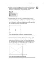
3. Move the mouse pointer to the midpoint of the top of the boss on
the Front view, and slowly move it up once the pointer includes a
small yellow icon representing the coincident relation, as shown in
Figure 4.5.
505434c04.indd 155 1/26/10 2:39:28 PM
Chapter 4 • Creating Your First Drawing
156
FIGURE 4.5 Icon next to pointer representing coincident relation
4. With the mouse pointer a small distance above the top of the boss,
click the left mouse button and release to begin drawing a line.
5. Draw the line vertically down, bisecting the lamp base.
6. When the line extends slightly below the bottom of the lamp base,
click and release the left mouse button to complete the line, as shown
in Figure 4.6.
FIGURE 4.6 Drawing a line to bisect the part model
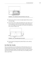
7. A section arrow will now be drawn where the line was created, and all
that is left to do is place the section view. Press F on your keyboard or
double-click the scroll wheel to fit the entire drawing on the screen.
8. Move the section view to the left of the Front view of the lamp base,
and then click and release the left mouse button.
9. In the Section View PropertyManager, enable the Flip Direction
option, as shown in Figure 4.7. Click the green check mark to accept
the changes.
505434c04.indd 156 1/26/10 2:39:28 PM
Add Views
157
FIGURE 4.7 Section View PropertyManager
The part has now been sectioned, giving you access to the inner geometry for
dimensioning. The new section view will automatically be labeled as Section
A-A, as shown in Figure 4.8, and if you were to create a second sectioned view, it
would be labeled as Section B-B.
NOte
In later chapters, you will be exploring the section views in more
detail, but in the meantime, we encourage you to explore the options available in
the Section PropertyManager. Simply select the section view in the graphics area,
and you will be able to make adjustments to the view in the PropertyManager.
FIGURE 4.8 Newly created section labeled Section A-A
Add Projected Views
The drawing template downloaded from the companion site already has pre-
defined views for the Front, Top, Right, and Isometric views. For many draw-
ings, these views are more than sufficient to fully describe the part. For this
particular part, you will need a couple of additional views in order to be able to
show the features on the back and bottom of the part.
505434c04.indd 157 1/26/10 2:39:28 PM
Chapter 4 • Creating Your First Drawing
158
Using projected views allows you to add these views and take on the properties
from the parent view such as Scale and Display Style. These new projected views
will also be connected to the original views, which means that if one of the views
is moved on the sheet, the dependant view will move along with it, ensuring that
the integrity of the drawing layout is preserved.
The following steps describe the process for creating the two new views from
the existing views instead of adding new views to the drawing:
1. Select the Right view by clicking and releasing the left mouse button
with the pointer inside the bounding area of the view.
2. Press S on your keyboard, and click the Drawing Commands button.
In the flyout, click the Projected View button.
3. Place the projected view of the back of the lamp base to the right of
the view.
4. Select the Front view of the lamp base, and once again click the
Projected View button in the shortcut bar.
5. Place the new projection below the Front view to create a view of the
bottom of the lamp base, as shown in Figure 4.9.
FIGURE 4.9 Projected view of bottom of lamp base
505434c04.indd 158 1/26/10 2:39:29 PM
Add Views
159
Once you place the projected views, you can move them around to clean up the
arrangement of the views on your drawing. But, you will only be able to move the
views in line with the projection unless you break the alignment of the view. Very
rarely will you need to break the alignment, but when the time comes, it is a good
skill to know. To be able to move a projected view elsewhere on the drawing, right-
click the view, and select Break Alignment in the Alignment flyout of the menu.
Add a Broken-out Section
A broken-out section is similar to a section view in that it is used to show the
internal geometry of a part, but instead of creating a new view that shows the
section, the parent view shows a broken area. This is equivalent to getting a
hammer and knocking off a chunk of the part to be able to see the inside. The
rest of the view shows the outside geometry, but in the broken-out section, the
inside geometry can be seen and dimensioned.
The advantage of using a broken-out section is that you will not need to create
a new view, which is extremely important if space is a consideration. Plus, if you
need to show only a small area of the part, it seems to be overkill to create a large
section view. In the example drawing, instead of creating a new section view to
be able to show the cross section of the AC cord hole, you’ll use a broken-out sec-
tion. Here’s how to do it:
1. Zoom in closer to the Bottom view by using the Zoom To Area button in
the Heads-up View toolbar or by using the scroll wheel on your mouse.
2. Select the Bottom view by clicking and releasing the left mouse but-
ton with the mouse pointer directly over the view.
3. In the Heads-up View toolbar, click the Display Style button, and click
the Hidden Lines Visible button in the flyout.
4. Select the Sketch tab in the CommandManager, and click the Spline tool.
5. Create a closed spline profile that completely surrounds the hid-
den lines that represent the hole on the back of the base by clicking
around the area as many times as required to create a spline that
somewhat represents the one shown in Figure 4.10.
NOte
Splines are 2D or 3D curves that are defined with multiple
points. As points are selected, a continuous smooth line is created. Splines
have many uses in SolidWorks, and you will be using them throughout your
career as a SolidWorks designer. But in this section, you will be using the
spline solely for creating the break-out section.
505434c04.indd 159 1/26/10 2:39:29 PM
Chapter 4 • Creating Your First Drawing
160
FIGURE 4.10 Creating a closed spline profile
6. After creating the closed spline profile, press S, and click the
Drawings button on the shortcut bar.
7. Click Broken-Out Section in the flyout.
8. Pan to the Back view of the lamp base, and select the circumference
of the hole, as shown in Figure 4.11. This will set the depth of the cut-
out to be exactly the center point of the hole.
FIGURE 4.11 Defining the depth of a broken-out section
WarNING
You can also define the depth of the broken-out sec-
tion in the PropertyManager, but if you take that approach, the depth will
not change as the surrounding geometry changes. This is why here you have
selected the circle that makes up the hole in the back of the lamp base. If the
location or size of the hole changes, the broken-out section will always be
based on the center of the hole.
9. Click the Preview option in the Broken-Out Section PropertyManager
to see what the broken-out section will look like when created (see
505434c04.indd 160 1/26/10 2:39:29 PM
Add Views
161
Figure 4.12). Make sure that the hole along with the lead-in chamfer
can be seen clearly without hidden lines.
FIGURE 4.12 Previewing the broken-out section
10. Click the green check mark in the Broken-Out Section
PropertyManager to complete the section.
11. Make sure the Bottom view is selected, and click the Hidden Lines
Removed button in the Heads-up View toolbar.
The broken-out section is now ready to be dimensioned, but because of the
size of the part, it may be a little difficult. So, in the next section, you will be
creating a detailed view that will allow you to apply dimensions to a larger repre-
sentation of the section.
Add a Detailed View
A detailed view is a partial view of a part that is most often at a larger scale than
the original part, allowing for greater detail. Using detailed views allows you to
dimension smaller features of a part without having to increase the overall scale
of the drawing, which is another way to conserve valuable sheet real estate. The
following steps will create a detail of the broken-out section created in the previ-
ous section:
1. Press S on your keyboard, and click the Drawing Commands button
in the shortcut bar.
2. In the Drawing Commands flyout, click the Detail View button.
3. Click near the center of the cross section of the hole in the broken-
out section you just created.
4. Drag the circle out from the center until the entire broken-out sec-
tion falls completely inside. Click the left mouse button to create the
circle, as shown in Figure 4.13.
505434c04.indd 161 1/26/10 2:39:29 PM
Chapter 4 • Creating Your First Drawing
162
FIGURE 4.13 Selecting part of the model to view in detail
5. Move the mouse pointer (with the detail view attached) to an empty
area of the drawing, and click the left mouse button to place the view
(see Figure 4.14).
FIGURE 4.14 Placing a detail view in the drawing
Unlike projected views and sections, a detail view can be moved anywhere in
the drawing sheet without limitations. In fact, if it is necessary, you can move the
detail view to a completely different sheet in the drawing. This is hugely helpful
if you are short on space in the drawing. Also, the scale of the detail view can be
changed independently from the rest of the views in the drawing. If you think the
current detail view is still too small at its current scale, select the view and adjust
the scale in the PropertyManager.
Annotate the Drawing
With all the required views created on the drawing, it is time to start applying
dimensions. Many users opt to add dimensions manually at this point, but that
approach would cause you to miss out on one of the greatest advantages to cre-
ating drawings in SolidWorks—bidirectionality. When done correctly, not only
are dimensions on the drawing updated when the part model is revised, but it
505434c04.indd 162 1/26/10 2:39:29 PM
Annotate the Drawing
163
can go the other way. If you make a change to a dimension in the drawing, the
model will update at the same time.
Dimensions that are manually placed on the drawing are actually reference
dimensions. Many users or organizations tend to change the system options of
SolidWorks to display reference dimensions as regular dimensions. Although not
technically correct, many users find that this approach to annotating a drawing
is quicker and easier. Reference dimensions that are manually added to a draw-
ing do not affect the part geometry but will update automatically as the part
is updated. However, if the part was not created with fully defined sketches or
the sketches were not defined with the design intent in mind, adding reference
dimensions would be quicker and easier than making changes to the part model.
With the steps described in this section, you will learn how to use the pre-
ferred method of annotating a drawing, but we would like to stress that it is not
the only accepted technique. Instead of adding dimensions to the drawing, you
will be importing the dimensions that you used to fully define the lamp base
model in both the sketches and features. This is one of the main reasons we’re
stressing the importance of design intent when defining sketches and features.
If you did the model correctly, the model dimensions that are imported into the
drawing would be those required to make the part per your design intent with-
out the need for adding too many extra dimensions.
Of course, as we have mentioned a few times already, there is more than one
way to do most things in SolidWorks. The steps described here are not the only
way and may not be the preferred method to some users, but we find these are
the easiest ways to annotate your drawing. In later chapters, you will be explor-
ing more options for annotating drawings that will also meet the requirements.
Under standing dim ensions
Throughout this book, we will often mention the various elements of a
dimension. It is important to understand what the different elements that
make up a dimension are before continuing.
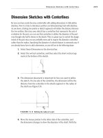
You can see a dimension, dimension line, and extension line here.
Extension Line Dimension Dimension Line
505434c04.indd 163 1/26/10 2:39:30 PM
Chapter 4 • Creating Your First Drawing
164
Dimension Lines
A dimension line is a straight or curved line with arrows used to specify
the extents and the direction of the dimension being applied. The dimen-
sion line is often broken to include the dimension value, depending on the
drafting standard used.
Extension Lines
Extension lines are lines drawn perpendicular to the dimension line and are
used to connect the dimension line to the part surface or points. A small gap
is made between the end of the extension lines and the area being dimen-
sioned to prevent the extension line from obscuring the area. If space is a
concern, the extension lines can be made oblique, or slanted, to the part.
Import Annotations
As long as the dimensions that you used to define the sketches in the part are
marked for use in the drawing, you can import those dimensions directly into
the drawing. Luckily, all the dimensions are automatically marked for drawing,
but if that weren’t the case, you could right-click dimensions and select Mark
For Drawing from the menu.
The dimensions that will be inserted into the drawing are the ones used in
the sketch and features to create the model. This is one of the reasons that
when creating sketches, the sketch should be dimensioned to define the design
intent. If you just arbitrarily placed dimensions in the sketches, the dimensions
imported into your drawing would not make any sense, and you might be forced
to manually dimension the drawing views.
Here are the steps to perform the import:
1. Press S to view the shortcut bar, and click the Annotations button to
view the tools available in the flyout.
2. Select Model Items from near the top of the menu.
3. In the Source/Destination section of the Model Items PropertyManager,
ensure that the source is set to Selected Feature. Also, make sure that
the Import Items Into All Views option is enabled in the same section.
505434c04.indd 164 1/26/10 2:39:30 PM
Annotate the Drawing
165
4. Depending on the feature being annotated, different types of dimen-
sions may be necessary. In the Dimensions section, you can specify
the type of dimensions that will be used for the selected feature. In
the Dimensions section of the PropertyManager, select the buttons
Marked For Drawing, Instance/Revolution Count, and Hole Callout.
5. In the Options section of the PropertyManager, select Include Items
From Hidden Features and Use Dimension Placement In Sketch. This
will make use of the layout that was used in the sketch of the part.
This is another example of why the extra steps taken in the creation
of the part can help with time management later in the process.
6. Rather than spending the time to fully dimension the drawing at this
time, only a couple of features will be annotated to save time. You can
always go back later to finish the rest of the features. For the time
being, start by zooming in on the Section A-A view. While the Model
Items PropertyManager is still active, click the inside face of the
counterbore for the boss, as shown in Figure 4.15.
FIGURE 4.15 Selecting a feature to import annotations
505434c04.indd 165 1/26/10 2:39:30 PM
Chapter 4 • Creating Your First Drawing
166
7. After selecting the inside face of the counterbore, the dimensions used
when creating the feature, including the chamfer, are imported into
the drawing. If those were the only dimensions that were meant to be
imported, you could click the green check mark in the PropertyManager
to fully import the dimensions and exit the command. But since you need
to select more features, you will keep the PropertyManager open so you
can continue importing dimensions. However, you can take this opportu-
nity to rearrange the dimensions before the view becomes too busy with
the other features. Rearrange the dimensions by clicking and holding the
left mouse button while dragging the dimensions into a better position.
8. As you arrange the dimensions already imported into the view, you
may find it impossible to arrange the dimensions to avoid crossing over
the view label, Section A-A. Rather than spend too much time with the
dimensions, you can move the label a little lower in the view. Just like
with dimensions, to arrange a label, click and hold the left mouse but-
ton while you drag the label to a better position. After you are done, the
view should look something like what is shown in Figure 4.16.
FIGURE 4.16 Arranging imported dimensions in the drawing view
9. Before exiting the Model Item PropertyManager, you need to import
one more feature at this time. Click the bottom line of the section view
to import the annotations for the width and the height of the base, as
shown in Figure 4.17. Notice that not only are dimensions imported
into the section view for the base, but there is also a dimension added
to the top view. This is because the Import Items Into All Views option
505434c04.indd 166 1/26/10 2:39:30 PM
Annotate the Drawing
167
was previously selected. The dimension added to the top view cannot be
shown in the section view, so the most logical place for the dimension
was automatically selected.
FIGURE 4.17 Importing dimensions for the base feature of the part
10. Click the green check mark in the Model Items PropertyManager to
exit the command.
Move Dimensions Between Views
After importing the annotations from the part model into the drawing views, it
is often necessary to clean up the dimensions. Since the annotations and dimen-
sions that are inserted are based on the location in the sketches and features of
the parts, they do not always translate well to the drawing space. Because of this,
you will need to rearrange the dimensions and annotations on the drawing by
distributing them throughout all the views and arranging them neatly. To dem-
onstrate this, you will be moving one of the dimensions for the base of the part
into another view that is a little more fitting.
Sometimes dimensions are imported into views that do not show the feature
being defined by the dimension. As you look through the dimensions that were
imported, you will see a dimension that is not attached to any feature. This dimen-
sion will need to be moved to the view that actually contains the feature. The fol-
lowing steps allow you to do this and still maintain the link to the part models:
1. Zoom and pan until you can see Section A-A and the Right view as
clearly as possible by spinning the scroll wheel to zoom and pressing
and holding the wheel while moving the mouse to pan.
2. Move the mouse pointer on top of the vertical 1.500 dimension in
Section A-A. When the dimension turns orange, click and hold the
left mouse button and hold down the Shift button on the keyboard.
505434c04.indd 167 1/26/10 2:39:30 PM
Chapter 4 • Creating Your First Drawing
168
3. While still holding the left mouse button and Shift on the keyboard,
drag the 1.500 dimension to the Right view, as shown in Figure 4.18.
FIGURE 4.18 Moving an imported dimension to another view
tIp
You can also copy dimensions to other drawing views by holding
the Ctrl button on the keyboard while dragging instead of holding the Shift
button.
4. It is safe to release the left mouse button once the mouse pointer icon
changes from a red circle with a line going through it to a blue dimen-
sion icon. Once you release the left mouse button, the dimension will
be moved to the view.
Arrange Dimensions
After moving dimensions to their appropriate drawing views, you can arrange them
in the views to eliminate dimensions that are crossing or are inside the visible lines
of the part. Also, in the case of the 1.500 dimension that was moved from the sec-
tion view into the Front view, sometimes the extension lines may be shown on the
wrong side of the part and should be fixed. Not only is this for aesthetic purposes,
but it also ensures that the reader of the print will be able to interpret the drawing
correctly.
505434c04.indd 168 1/26/10 2:39:30 PM
Annotate the Drawing
169
How dimensions are shown on a drawing can have a huge impact on how well it is
interpreted. If dimensions are crossing over each other or lie within the part itself,
the reader of the drawing can make potentially expensive mistakes. Sometimes
dimensions having to be placed in less than desirable spots on the drawing are
unavoidable, but they can often be resolved by adding extra views or just moving
them to another view. To arrange dimensions, do the following:
1. Zoom in on the Top view of the lamp base with whatever method you
have become most comfortable with so far.
2. Select the vertical 4.000 dimension by clicking and holding the left
mouse button while the mouse pointer is directly over the dimension
and it turns orange, as shown in Figure 4.19.
FIGURE 4.19 Select dimension to be moved to another drawing view
3. Drag the dimension while holding the left mouse button horizontally
to the other side of the part away from the edge. As you move the
dimension, it will snap to different distances from the model edge. The
distance is used to ensure that all dimensions on the drawing have a
uniform distance between the model edge and first dimension, as well
as stacked dimensions. Move the dimension to the first snap point
beyond the visible edge of the part, as shown in Figure 4.20. When
505434c04.indd 169 1/26/10 2:39:30 PM
Chapter 4 • Creating Your First Drawing
170
arranging the dimensions, try to avoid placing dimensions inside the
visible outline of the part. If at all possible, make every attempt to
arrange the dimensions in such a way that they do not cross over each
other. Sometimes it may be easier to move the dimension to another
view to eliminate the chance of dimensions crossing each other.
FIGURE 4.20 Moving a dimension to make the drawing more legible
Extend the Extension Lines
After moving the 1.500 dimension, you may have noticed that the extension line
does not extend all the way to the part. To have a clean-looking drawing, you
will need to extend the extension lines up to the features being defined. This is
probably the only drawback to importing dimensions from the model and then
distributing them to the various views. But luckily it is a simple task that can be
taken care of quickly:
1. Zoom in closer to the Front view.
2. Click the vertical 1.500 dimension by clicking and release the left
mouse button with the mouse pointer directly over the dimension.
3. Click and hold the blue handle point on the dangling extension line of
the dimension, and drag it horizontally until the point on the model
being dimensioned is highlighted with an orange dot. Release the left
mouse button. After extending the line to the part, the dimension
should appear as shown in Figure 4.21.
You can adjust the
offset distance
of dimensions
in the Document
Properties tab of
the Option window.
In the Document
Properties tab,
select Dimensions
in the left pane and
then adjust the value
in the Offset dis-
tances section.
505434c04.indd 170 1/26/10 2:39:31 PM
Annotate the Drawing
171
You may be asking yourself why one would even care about the gap between
the feature and extension line. It is considered good drafting practices, per ASME
Y14.5, to ensure that there is a uniform gap between the outline of the part and
the extension line. Sometimes this is not possible because of the feature being
defined, but when you can control it, there should be a gap.
FIGURE 4.21 Lengthening the extension line of a dimension
NOte
You can adjust the default gap distance that is automatically
inserted by SolidWorks in Document Properties. Select Dimensions in the
left pane of the window and adjust the value in the Gap field in the Extension
Line section.
Change Diameter Dimensions
You can specify a diameter dimension for a circle on a drawing in many ways.
Although not very common, it is perfectly fine to keep the linear diameter dimen-
sions that are currently being shown in the example drawing. But we prefer show-
ing diameters of a circle with a leader dimension.
Instead of deleting the current diameter dimensions, you can just adjust the
display to be shown with leaders instead of a linear dimension. Perform the fol-
lowing steps on all diameter dimensions that are currently shown with a linear
dimension:
1. Select Model Items in the Annotations flyout of the shortcut bar.
2. Zoom into the Back view of the part, and select the inner circle of the
AC cord hole to import the dimensions, as shown in Figure 4.22. The
dimensions that locate the hole in the back of the lamp base will be
shown. Since the option for importing items in all views is selected,
505434c04.indd 171 1/26/10 2:39:31 PM
Chapter 4 • Creating Your First Drawing
172
the dimension for the size of the hole will automatically be inserted
into Detail B. Click the green check mark in the PropertyManager to
exit the command since you will not need to import any other dimen-
sions at this time.
FIGURE 4.22 Importing the dimensions for AC cord hole
NOte
If the Import Items Into All Views option was not selected, the
diameter dimension would have been imported into the Back view. Normally, for
this feature, this would have been the ideal situation, but for the sake of demon-
stration, we will allow the diameter dimension to be imported into the detail.
3. While holding the Shift key, move the .400 diameter dimension from
Detail B to the Back view. After moving the dimension, do not close
the Dimension PropertyManager for the selected dimension.
4. In the Dimension PropertyManager, select the Leaders tab.
5. In the Witness/Leader Display section, click the Diameter button.
6. Select and hold the diameter dimension, and arrange it in the view so
it sits outside the part and does not cross over any other dimension in
the view.
505434c04.indd 172 1/26/10 2:39:31 PM
Annotate the Drawing
173
When you are finished arranging the dimensions, they should look something
like the views shown in Figure 4.23.
FIGURE 4.23 Dimensions in cleaned-up drawing views
Reverse Directions of Dimension Arrows
Sometimes, depending on the size of the feature begin dimensioned, the arrows will
cross over each other, obscuring the area being defined. Since you can’t enlarge the
feature to make the arrows appear properly on the dimension, you can reverse the
arrow direction. An example of this is the diameter dimension for the AC cord hole.
Since the diameter is so small, the arrows are on the inside of the hole, so you need
to reposition the arrows to be on the outside. To reverse the direction of the arrows,
do the following:
1. Zoom in closer to the .400 diameter dimension. If it’s not selected already,
select the dimension by clicking and releasing the left mouse button. Not
only will the dimension be highlighted, but the point where the dimen-
sion attaches to the hole edge and the endpoints of the arrows will be
highlighted on the fattest end of the arrow, as shown in Figure 4.24.
2. To flip the arrowheads of the dimension, click one of the highlighted
arrow endpoints. The arrowhead attached to the leader will flip sides
to the outside of the circular edge, and the second arrow will disap-
pear, as shown in Figure 4.25.
Not only can the arrowheads for diameter dimensions be reversed, but all
dimensions, even on linear dimensions, can be reversed. As you scan the rest of
the drawing, you may see a few dimensions that may need to be updated in this
manner; if that is the case, this is the best time to update the dimensions.
505434c04.indd 173 1/26/10 2:39:31 PM