SolidWorks 2010- P5 doc
Bạn đang xem bản rút gọn của tài liệu. Xem và tải ngay bản đầy đủ của tài liệu tại đây (562.98 KB, 30 trang )
Create a Base Extrusion
89
2. Click the downward-pointing arrow next to the Corner Rectangle com-
mand to show the available rectangle types. Select Center Rectangle.
This creates a rectangle from a center point in the sketch.
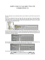
3. After selecting Center Rectangle in the shortcut bar, the mouse
pointer will update to show the Sketch tool selected with a small icon
next to a pencil, as in Figure 3.4. Select the sketch origin in the cen-
ter of the screen by clicking and releasing the left mouse button with
the tip of the pencil directly on top of the origin.
FIGURE 3.4 Creating a rectangle from a center point in the sketch
4. After releasing the mouse button when selecting the sketch origin,
move the mouse pointer away from the origin. A rectangle will be
shown but will not actually be created until clicking the mouse but-
ton again. Next to the mouse pointer, the X and Y coordinates of the
mouse pointer will be displayed in relation to the rectangle origin
instead of the sketch origin, as in Figure 3.5.
FIGURE 3.5 Coordinate display while sketching
505434c03.indd 89 1/27/10 1:47:49 PM
Chapter 3 • Creating Your First Part
90
5. To create the rectangle, after dragging to the shape of the rectangle,
click the left mouse button once again. SolidWorks will apply the
appropriate relations to the rectangle including making the edges
horizontal and vertical and making the center point coincident to the
sketch origin, as shown in Figure 3.6.
FIGURE 3.6 Undimensioned sketch with relations
More About Rectangles
When you were selecting Center Rectangle from the shortcut bar, you may have
noticed that there are actually five different types of rectangles that can be used
in sketches. Each of the five rectangles offers its own advantages, and you will
be using each of them at least a few times during your time in SolidWorks. Here
is a quick explanation of the five types of rectangles available in SolidWorks:
Corner Rectangle T h e Corner Rectangle option creates one of the most com-
monly used rectangles in SolidWorks. A corner rectangle is created by selecting
two points that make up the opposite corners of the rectangle.
Center Rectangle T h e Center Rectangle option creates a rectangle by selecting
the center point and then one of the corner locations. The opposite corners of
the rectangle are connected with a hidden line, and a point is placed where the
lines intersect.
3 Point Corner Rectangle T h e 3 Point Corner Rectangle option creates a rect-
angle at an angle by selecting the location of three of the corners. The first point
specifies the origin of one of the corners. The second point determines the angle
of the rectangle in relation to the first point selected. The third point defines the
width or height of the rectangle.
3 Point Center Rectangle T h e 3 Point Center Rectangle option is a combina-
tion of the Center Rectangle and 3 Point Corner Rectangle choices. It allows
you to specify a center point of the rectangle; then the angle is defined with the
You’ll further dene
sketch relations
throughout the book
as the need arises.
505434c03.indd 90 1/27/10 1:47:51 PM
Create a Base Extrusion
91
second point and specifies the midpoint of one the sides. The third point defines
the width of the rectangle.
Parallelogram T h e Parallelogram option is drawn much like a rectangle (which
is a parallelogram as well). The parallelogram is defined with three points that
coincide with three of the corners. The first point defines the origin of parallelo-
gram, the second point defines the angle of the base of the parallelogram, and
the third point defines the angle and length of the adjacent edge.
Define the Sketch
With the rectangle drawn, you could create the extrusion of the base feature
and continue modeling, but it is considered very bad practice to not fully define
your sketch. You will be tempted many times in the future to not fully define a
sketch in order to save a little bit of time, but keep in mind that the extra couple
of minutes you take to do something right the first time will save you even more
time in the long run.
Not only will you avoid time-consuming errors by fully defining your sketch,
but you will also be able to better capture your design intent. Design intent is
how your part reacts as parameters are changed. For example, if you have a hole
in a part that must always be .250
≤ from an edge, you would dimension to the
edge rather than to another point on the sketch. As the part size is updated, the
hole will always be .250
≤ from the edge.
Since this sketch only has a rectangle and no other sketch entities, the only
design intent to capture is the overall size and orientation of the rectangle. When
the rectangle was created, the orientation was defined with the center point becom-
ing coincident to the sketch origin and the sides being made horizontal and verti-
cal. That only leaves defining the size of the rectangle. This involves specifying the
height and width of the rectangle by using dimensions. To specify the dimensions
of your rectangle, do the following:
1. With the mouse pointer anywhere in the graphics area, press S on
your keyboard to open the shortcut bar.
2. To view all the available dimension types in sketches, select the
downward-pointing arrow next to the Smart Dimension icon.
3. Select the very first option, Smart Dimension. The mouse pointer will
change to include an icon that represents the Smart Dimension tool.
You can tell whether
an active sketch
is under-dened
or fully dened by
looking in the status
bar, as described in
Chapter 1.
505434c03.indd 91 1/27/10 1:47:53 PM
Chapter 3 • Creating Your First Part
92
4. There are a few ways to apply dimensions to sketch entities. One way
is to dimension to points in the sketch to define their relationship to
each other. Select the upper-left corner of the rectangle by clicking
the corner. The corner will be highlighted with a small filled-in circle
when the mouse pointer is in the correct position, as in Figure 3.7.
FIGURE 3.7 Selecting a point in a sketch for a dimension
5. Move the mouse pointer over to the upper-right corner of the rect-
angle, and click that point, as in Figure 3.8.
FIGURE 3.8 Selecting second point for dimension on sketch
6. A dimension will now be shown with the current width of the rectan-
gle. Drag the dimension anywhere you want it to sit. We usually like
to place it a short distance from the area being dimensioned since it
makes it easier to determine which feature is being dimensioned in
the sketch.
7. Click the left mouse button once again to place the dimension.
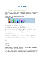
8. Once you place the dimension, the Modify window will pop up and
allow you to specify the value of the dimension placed, as shown in
Figure 3.9. You can choose to scroll the wheel that spans the entire
505434c03.indd 92 1/27/10 1:48:00 PM
Create a Base Extrusion
93
length of the number field, but this is extremely slow and inaccurate.
Instead, using the keyboard, enter the width of the rectangle as 6.
FIGURE 3.9 Defining the width of the rectangle
9. To accept the value entered and update the width of the rectangle,
click the green check mark (or press the Enter key on the keyboard).
The width of the rectangle will update, and the dimension will now
show the new distance.
10. Now you need to specify the height of the rectangle. As mentioned
earlier, there are a number of ways to place dimensions in a sketch.
This time, instead of selecting the corners of the rectangle, select
the line that makes up the left side of the rectangle, as shown in
Figure 3.10.
FIGURE 3.10 Applying dimension by selecting a sketch segment
11. The entire length of the line will automatically be dimensioned. Drag
the dimension to the side of the rectangle, and place it by clicking the
left mouse button once again.
505434c03.indd 93 1/27/10 1:48:09 PM
Chapter 3 • Creating Your First Part
94
12. Enter the new height of the rectangle to be 4, as shown in Figure 3.11.
You do not need to specify a unit since you specified the units in the
document settings.
FIGURE 3.11 Defining the height of the rectangle
13. Click the green check mark to accept the new value and update the
height of the rectangle.
14. To exit the sketch, click the Exit Sketch icon in the upper-right cor-
ner of the graphics area, as shown in Figure 3.12. This area of the
graphics window is referred to as the confirmation corner and allows
you to exit most editing modes while working in SolidWorks.
FIGURE 3.12 Confirmation corner of graphics area
Dimension Types in Sketches
When you selected the Smart Dimension tool in the shortcut bar while creating
the sketch, you may have noticed that there were a few more dimension types
505434c03.indd 94 1/27/10 1:48:18 PM
Create a Base Extrusion
95
available. The Smart Sketch dimension type will be the type you will use most of
the time, but it still wouldn’t hurt to become familiar with all the dimension types:
Smart Dimension T h e Smart Dimension tool will be your most used tool when
defining sketch elements. Smart Dimension automatically selects the dimen-
sion type that will be used based on the sketch entities that are selected. Not
only does Smart Dimension determine the dimension type based on the type of
entity selected, but it also can choose another dimension type, such as angles
and point-to-point dimensions, based on where you place the dimensions.
Horizontal Dimension T h e Horizontal Dimension tool creates a dimension
where the dimension line is horizontal and the extension lines are vertical
regardless of the entity selected in the sketch.
Vertical Dimension T h e Vertical Dimension tool creates a dimension where the
dimension line is vertical and the extension lines are horizontal regardless of
the entity selected in the sketch.
Ordinate Dimension In ASME Y14.5, ordinate dimensions are referred to as
rectangular coordinate dimensions without dimensions lines—that’s quite a
mouthful. Luckily, in SolidWorks they are only referred to as ordinate dimensions,
and you create them with the Ordinate Dimension tool. This type of dimension
is shown with the dimension’s value on the extension line without the addition
of dimension lines or arrows. In a sketch, a zero dimension is specified, and then
each subsequent dimension is shown with the value of the distance from the zero
dimension. Like in smart dimensions, the Ordinate Dimension tool automatically
determines the orientation of the dimension based on the entities selected.
Horizontal Ordinate Dimension T h e Horizontal Ordinate Dimension tool cre-
ates a dimension with the value above the extension line without a dimension
line or arrows. It will only place ordinate dimensions that are horizontally
related to the selected dimension origin.
Vertical Ordinate Dimension T h e Vertical Ordinate Dimension tool creates a
dimension with the value next to the extension line without a dimension line or
arrows. It will only place ordinate dimensions that are vertically related to the
selected dimension origin.
Use Instant3D
With your first sketch created, you are now ready to create the base feature. As
with most areas in SolidWorks, there is more than one way to create an extru-
sion. Most users will, for this feature, create an extrusion using the Extruded
505434c03.indd 95 1/27/10 1:48:18 PM
Chapter 3 • Creating Your First Part
96
Boss/Base command on the Features tab of the CommandManager. That is a
perfectly fine approach to creating extrusions, but you’ll learn how to quickly
create extrusions by using Instant3D.
Instant3D was introduced to SolidWorks in the 2008 release; it allows you
to create and modify features by using drag handles and on-screen rulers.
Ultimately, this means fewer mouse clicks and less keyboard entry, which will
make modeling and modifying parts and assemblies much quicker and easier.
The Extruded Boss and Extruded Cuts options still serve an important role in
SolidWorks, and you will definitely be spending some time on those commands
later, but I wanted you to become familiar with using Instant3D since it is a
method that is largely ignored by many users. Here’s how to use it:
1. Using the middle mouse button to rotate the view, or by pressing
Ctrl+7 on keyboard, rotate the sketch to an isometric view or some-
where close to isometric. Since using Instant3D requires dragging
the sketch out to extrude, you need to have a good angle on the
sketch in order to do this. It is not possible to drag a sketch that is
normal to the viewing plane.
2. Before being able to use Instant3D, you need to ensure that the abil-
ity is enabled. Turn on Instant3D by clicking the Features tab in the
CommandManager and clicking the Instant3D button, if disabled.
3. With Instant3D enabled, select any of the lines in the sketch. A green
arrow, or drag handle, will be shown originating from the selected
point on the sketch perpendicular to the sketch plane. If you do not
see a drag handle when selecting the sketch line, ensure that you have
exited the sketch and that Instant3D is enabled per the previous step.
4. Click and hold the left mouse button with the mouse pointer any-
where on the drag handle. You will know you are directly on the drag
handle when its color changes from green to amber.
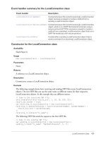
5. While still holding the left mouse button, drag the arrow away from
the sketch. This will create the actual extrusion. Using the on-screen
ruler, you can specify the extrusion height. With the mouse pointer
directly on top of the on-screen ruler, specify the value of 1.5, and
release the left mouse button, as shown in Figure 3.13.
505434c03.indd 96 1/27/10 1:48:22 PM
Create a Base Extrusion
97
FIGURE 3.13 Creating an extrusion using Instant3D
Understanding the on-screen ruler is an important aspect of using Instant3D.
The on-screen ruler allows you to precisely select the value of any operation that
uses a drag handle to create or modify geometry. As you drag the drag handles, the
ruler will appear on-screen running perpendicular to the feature being dragged.
As you drag, the ruler will show the distance from the origin, and a green line and
number with your current value in relation to the origin will be shown. Figure 3.14
shows the on-screen ruler as it appears while moving the mouse pointer.
FIGURE 3.14 On-screen ruler in Instant3D
As you drag the location of your mouse pointer in relation to the on-screen
ruler, you can snap the values to the ruler increments. If your mouse pointer
is not directly over the ruler, the value does not snap, and you can change the
value freely. This approach is not at all precise.
On the on-screen ruler, two levels of increments appear. The major increments
are shown with longer ticks and a number value. The intermediate increments are
shown with shorter lines and no numbers. The numbers and increments shown are
based on your current view. As you zoom in closer, the increments become finer,
giving you more accuracy, and as you zoom out, the increments are less accurate.
Throughout this
book you’ll learn
about tools such
as Instant3D,
FilletXpert, and
others that reduce
mouse clicks and
save time.
505434c03.indd 97 1/27/10 1:48:26 PM
Chapter 3 • Creating Your First Part
98
When dragging the drag handle, when the mouse pointer is over the outside
of the ruler with the larger increments, the values will only snap to the number
increment. At any point you can release the mouse button when your desired
value is highlighted green. Figure 3.15 shows the mouse snapping to the larger
increments of the on-screen ruler.
FIGURE 3.15 Snapping to major increments on the on-screen ruler
If the mouse pointer is over the inside of the ruler with the finer increments,
you will be able to select a value that is a little more precise. The smaller hatch
marks will be displayed with a value when the increment is active while drag-
ging. Figure 3.16 shows how the mouse will snap to the smaller increments.
FIGURE 3.16 Snapping to minor increments on the on-screen ruler
tIp
Even when Instant3D is not activated, the on-screen ruler can be used
when using the Extruded Boss, Extruded Cut, Extruded Surface, Revolved
Boss, Revolved Cut, Revolved Surface, and Base Flange commands.
505434c03.indd 98 1/27/10 1:48:34 PM
Add an Extruded Cut
99
Add an Extruded Cut
In the previous section, you created the base feature by drawing a sketch and
then creating an extrusion with Instant3D. You can easily continue modeling
the lamp base solely with this technique, but I want to make sure you are aware
of the various ways to create a model. As you become familiar with the different
approaches to modeling, you can use the technique that is best suited for the
task at hand.
Create a Sketch on a Planar Face
For the next feature of the lamp base, you’ll cut away an angled section of the
base to create a more appealing look. Instead of creating the sketch first and
then selecting the feature, you will need to select the feature first. This will
eliminate a few mouse clicks, and when you are working, every mouse click
saved saves you time. Here’s how to do it:
1. With the lamp base in an isometric view, press S on your keyboard to
display the shortcut bar. Select the downward-pointing arrow next to the
Extruded Cut icon.
2. The menu will display the five cut features available in part modeling.
For this particular feature, you will be creating just a simple linear
cut, so select Extruded Cut from the top of the list.
3. After selecting Extruded Cut, the PropertyManager will inform you
that must select a plane, planar face, or edge on which to create a
sketch or select an existing sketch. Since you have not created a
sketch yet, you will need to select a plane or face.
4. Select one of the side faces of the block, as shown in Figure 3.17. This
is the face on which you will create the sketch for the cut.
5. As soon as the face of the block is selected, a new sketch will be cre-
ated on the side. Although you could make the sketch from this view-
ing angle, it is often easier to change the view for the sketch plane to
be normal to the viewing plane. To change the view to be normal to
505434c03.indd 99 1/27/10 1:48:35 PM
Chapter 3 • Creating Your First Part
100
the viewing plane, press Ctrl+8 on your keyboard, or select Normal
To from the Heads-up View toolbar. You now have a canvas on which
to create your next sketch.
FIGURE 3.17 Selecting a face on which to create a sketch
6. Press S on your keyboard to view the shortcut bar. Select the downward-
pointing arrow next to the Line icon.
From the two commands shown in the flyout menu, click Line.
NOte
It is not necessary to view the menu flyout each time you want to
select a command. For demonstration purposes, you will see all the available
tools in each flyout. The last command selected in each flyout will become
the icon in the shortcut bar. Selecting this button will initiate the command.
7. After clicking the Line command in this toolbar, the mouse pointer
will change to a pencil with a blue line next to it to show that you
can draw a line. Select the top-left corner of the face of the block by
pressing and releasing the left mouse button. When the point can
be selected, a small orange circle will be shown on the corner, as in
Figure 3.18.
8. Move the mouse pointer horizontally along the top edge of the face
a little more than half of the length of the edge. The edge of the part
will be highlighted to show that the line being created is collinear
with the edge. For this case, this is exactly what you want to achieve.
505434c03.indd 100 1/27/10 1:48:39 PM
Add an Extruded Cut
101
Click the left mouse button and release to draw the line, as shown in
Figure 3.19.
FIGURE 3.18 Creating a sketch on a selected feature
FIGURE 3.19 Drawing a line along an edge
9. Click and release the left mouse button while the mouse pointer has
highlighted the left edge of the part, as in Figure 3.20.
FIGURE 3.20 Drawing a line to create an angled cut
10. To complete the sketch, click and release the left mouse button with the
mouse pointer directly over the original point at the upper-left corner
of the part, as shown in Figure 3.21. Since the profile created is properly
closed, moving the mouse will not create another line segment.
505434c03.indd 101 1/27/10 1:48:48 PM
Chapter 3 • Creating Your First Part
102
FIGURE 3.21 Closing the profile
Fully Define the Sketch
Two of the lines in the sketch are black to represent that these segment direc-
tions are fully defined. Although you did not specify any relations, SolidWorks
assumed that the points you selected on the corner and the two edges are coin-
cident. These automatically placed relations were enough to define these two
segments, leaving only the hypotenuse (the angled segment) of the triangle
drawn. You can tell that this segment is not fully defined since it is shown as a
blue color. To fully define the sketch, you must follow these steps:
1. Press the S button on your keyboard, and select Smart Dimension in
the shortcut bar.
2. The first step to fully define the sketch is to specify the length of one of
the segments of the sketch. This is a perfect example of dimensioning a
sketch for design intent. There are a number of ways to fully define the
sketch, but you need to ensure that the top of the base always includes
enough room for the shaft you will be modeling later. To do this, instead
of dimensioning the length of the top segment, you will dimension the
top-flat area of the lamp base. Click the top-right corner of the part and
the corner of the sketch, as shown in Figure 3.22.
FIGURE 3.22 Dimensioning for design intent
505434c03.indd 102 1/27/10 1:48:52 PM
Add an Extruded Cut
103
3. Place the dimension, and update the dimension value to be 1.625. This
will ensure that no matter how the part dimensions are changed, the
top of the part will always remain the same. The one end point of the
hypotenuse is not defined, so it will change from blue to black.
4. You can tell by the blue line in the sketch that it is not fully defined
yet. Once again, you can define the sketch any number of ways, but
this time you’ll specify the angle of the hypotenuse in relation to the
top edge of the part. While still in Smart Dimension mode, select the
hypotenuse of the triangle, as shown in Figure 3.23.
FIGURE 3.23 Applying dimension to the hypotenuse
5. Next select the top of the segment of the sketch, as in Figure 3.24. The
dimension will change from a linear dimension to an angular dimension.
FIGURE 3.24 Specifying the angle of sketch segments
6. Just for demonstration purposes, without clicking the left mouse but-
ton, move the dimension around, and you will notice that the angu-
lar dimension changes based on the angle being defined. Place the
dimension inside of the triangle, and click the left mouse button.
7. In the Modify window, enter the value 20, and click the green check
mark to accept the value. Figure 3.25 shows the resulting sketch.
505434c03.indd 103 1/27/10 1:48:55 PM
Chapter 3 • Creating Your First Part
104
FIGURE 3.25 Sketch prepared to launch the Extruded Cut command
The sketch is now fully defined, as can be seen by all of the segment’s black
color. If you need to make sure, you can always glance at the status bar and see
whether the status has changed to Fully Defined.
Explore Options for Creating an Extruded Cut
Now that the sketch is drawn, it will make sense why you started the process
by initiating the Extruded Cut command instead of drawing a sketch separately
and then doing an extruded cut. Once you exit the sketch, the Extruded Cut
command will automatically launch, and the sketch that was drawn will be used
for the cut. You can use a number of options to create an extruded cut, so here
you’ll take a couple of minutes to explore a few of them. Here is one option:
1. In the confirmation corner, click the Close Sketch icon (Figure 3.26).
FIGURE 3.26 Closing the sketch in the confirmation corner
2. The Extruded Cut command will automatically start. The inside of
the sketch profile will be highlighted to show that it will be used for
the extrusion (see Figure 3.27), and the PropertyManager will show
the parameters.
505434c03.indd 104 1/27/10 1:49:04 PM
Add an Extruded Cut
105
FIGURE 3.27 Highlighted portion of sketch profile to be used for extrusion
3. Switch to an isometric view in either the Heads-up View toolbar or by
pressing Ctrl+7 on your keyboard.
4. Even though you are not creating the extruded cut using Instant3D,
you can click and hold the left mouse button while the mouse pointer
is over the drag arrow to drag out the extrusion.
While dragging, the on-screen ruler will be displayed, allowing
you to select the depth of extrusion without entering a value, as in
Figure 3.28. The depth of the extrusion will be updated in the Depth
field of the PropertyManager.
FIGURE 3.28 Specifying the depth of an extrusion using the on-screen ruler
5. Below the Depth field in the PropertyManager, there is a Flip Side To
Cut check box, as shown in Figure 3.29. Select this box to cut every-
thing on the model instead of the shape created with the profile of
the sketch. Deselect Flip Side To Cut, and the extruded cut will be the
profile of the sketch, as shown in Figure 3.30.
505434c03.indd 105 1/27/10 1:49:11 PM
Chapter 3 • Creating Your First Part
106
FIGURE 3.29 Flip Side To Cut option in the PropertyManager
FIGURE 3.30 Flip Side To Cut preview in the graphics area
6. At the top of the Direction 1 section of the PropertyManager, next to
the End Condition field, click the Reverse Direction button, as shown
in Figure 3.31. The preview of the cut will change directions. Using this
option will allow you to specify the direction of the cut if the default
direction of the extrusion was not what you actually intended to cut.
505434c03.indd 106 1/27/10 1:49:15 PM
Add an Extruded Cut
107
Since there is no model geometry in this direction, click the Reverse
Direction button once again to return it to its previous direction.
FIGURE 3.31 Reverse direction of the extrusion in the PropertyManager
The last extrude parameter you'll see at this time is End Condition. The End
Condition parameter specifies how the extrusion will be terminated on the model.
For this particular model, there are a few different ways you can terminate the
extrusion, and each will work, but there are a couple that are more fitting than
others. Up to this point, you have been specifying the depth of the extrusion with
a value whether it is entered in the PropertyManager or via the on-screen ruler.
Specifying the depth of extrusion is required when the End Condition parameter
is set to Blind. This is the default End Condition parameter of all extrusions, and it
will probably be your most used, but you should look at a couple more examples.
To terminate the extrusion by changing the end condition, do the following:
1. Click the downward-pointing arrow next to the End Condition field.
If you are not sure which one is the End Condition field, right now it
should be set to Blind.
505434c03.indd 107 1/27/10 1:49:19 PM
Chapter 3 • Creating Your First Part
108
2. In the End Condition field, eight types of conditions are available, but
not all of them will work for what you need to do with this condition.
The first end condition that will work is Through All. Select Through
All from the End Condition field.
In the graphics area, you will see the extrusion preview go through
the entire part, as in Figure 3.32. This will work in this case, but it is
not exactly the correct one. Through All should be reserved for when
it is necessary to create an extrusion that goes through multiple fea-
tures on a part.
FIGURE 3.32 Using the Through All End condition for an extrusion
3. The next End Condition parameter that will work in this case is the
Up To Surface condition. Select it from the End Condition field.
4. You will need to select a surface on which to terminate the extrusion.
Select the back face of the model, and you will see the extrusion pre-
view cut through the part, as in Figure 3.33.
505434c03.indd 108 1/27/10 1:49:26 PM
Add an Extruded Cut
109
FIGURE 3.33 Using the Up To Surface end condition for an extrusion
The problem with selecting this condition is that if later during
part revisions the face gets removed by a feature above this cut, this
feature will fail and generate an error. For that reason alone, try to
avoid this end condition unless it is absolutely necessary.
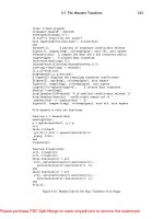
5. Lastly, the end condition that is perfect for the particular feature
is Up To Next. Selecting this end condition terminates the current
extrusion at the next face that is large enough to include the entire
sketch profile. Select Up To Next, and you will see the extrusion pre-
view go through the entire part, as shown in Figure 3.34.
FIGURE 3.34 Using Up To Next end condition for an extrusion
6. At this point, you are finished with the extrusion, and there are no
other parameters that need to be selected. Click the green check
mark in the Extrude PropertyManager to create the cut.
7. It is now probably a good time to save your work so far just in case
something happens. Click the Save button in the menu bar, or press
Ctrl+S on your keyboard. You will notice that you were not prompted to
enter a filename or location since you defined that information earlier.
505434c03.indd 109 1/27/10 1:49:35 PM
Chapter 3 • Creating Your First Part
110
Add Boss Extrusions
The next step in creating the lamp base is adding a boss on the part that will later
be used to support the lamp shaft. In efforts to expose you to additional methods
of modeling, you will create a sketch first and then initiate the command. You
could easily create the boss using one of the two previously described methods,
but it is a good idea to be familiar with as many techniques as possible.
To add a boss, do the following steps:
1. Select the top surface of the lamp base with the mouse pointer, and
a context toolbar will be displayed providing you with the most com-
monly used tools available for the selected face. Click the Sketch
Icon in the toolbar, as shown in Figure 3.35. A new sketch named
Sketch3 will be created on the selected face and will show in the
FeatureManager design tree.
FIGURE 3.35 Creating a sketch for a boss
NOte
As with the context toolbar when selecting items in the
FeatureManager, the context toolbar in the graphics area will disappear if
you move the mouse away. If the toolbar disappears, right-click the surface
to click the Insert Sketch button.
2. Press Ctrl+8 on your keyboard or select Normal To from the
Heads-Up View Toolbar toolbar to make the sketch plane parallel to
the viewing plane.
505434c03.indd 110 1/27/10 1:49:41 PM
Add Boss Extrusions
111
3. Press S on your keyboard to display the shortcut bar, and click the
downward-pointing arrow for the Circle button. You will see there are
two available circle types for creating circles on a sketch. Select the Circle
tool. The mouse pointer will change to include a pencil and a circle.
4. With the mouse pointer on the top surface of the lamp base, press
and release the left mouse button to specify the center point of the
circle, as shown in Figure 3.36. It does not matter where the circle is
placed since you will be adding relations and dimensions to define its
final location on the part in the next few steps.
FIGURE 3.36 Selecting the center point of a circle
5. Drag the mouse pointer away from the center point specified in the
previous step. As you move the mouse pointer, a circle will be shown
as a preview, and the radius will dynamically update next to the mouse
pointer. Since you will be specifying the actual diameter of the circle
with a dimension, this value being shown is used as a reference only
while creating the circle. Click and release the left mouse button once
again to create the circle, as shown in Figure 3.37.
FIGURE 3.37 Drawing a circle for a boss extrusion
505434c03.indd 111 1/27/10 1:49:47 PM
Chapter 3 • Creating Your First Part
112
6. Now all that is left to do is specify the size and location of the circle to
fully define the sketch prior to creating the boss extrusion. Press S on
your keyboard to view the shortcut bar, and click Smart Dimension in
the toolbar.
7. With the mouse pointer, select the circle circumference by clicking
and releasing the left mouse button, as shown in Figure 3.38.
FIGURE 3.38 Selecting the circle to specify the diameter
8. A dimension for the diameter will be displayed by default since the cir-
cle is complete. If you were selecting an arc such as a fillet, the dimen-
sion will automatically display the radius value. Place the dimension
anywhere in relation to the circle by pressing and releasing the left
mouse button.
9. In the Modify window, enter the diameter value of 1.25, and click the
green check mark to accept this value, as shown in Figure 3.39.
FIGURE 3.39 Using Smart Dimension to specify the diameter of a circle
505434c03.indd 112 1/27/10 1:49:53 PM
Add Boss Extrusions
113
10. Now you need to specify the location of the circle in relation to the
rest of the part in order to define its design intent. Since this circle
is going to be the boss that supports the lamp shaft, you want it to
always be .900 inches from the back edge of the part. With the Smart
Dimension tool still active, click the circumference of the circle again.
Once again, the Smart Dimension tool, based on your selection,
attempts to predict your action by providing you with the diameter
dimension. If this was the only selection made in the sketch, it would
be the only option available, but you will need to define your selec-
tion even more to properly dimension the circle.
11. Move the mouse pointer directly above the back edge of the part.
When the edge is highlighted, press and release the left mouse but-
ton, as shown in Figure 3.40. With this additional selection, the Smart
Dimension tool now has enough information to determine that the
feature requires a vertical dimension, and it is automatically updated.
FIGURE 3.40 Defining a vertical location for a feature
12. Move the mouse pointer to the side of the circle, and press and
release the left mouse button to place the dimension. In the Modify
window, enter the value of .9 to make the center of the circle always
be .900 inches from the back edge of the part no matter what dimen-
sional changes that part may go through during a revision. Exit the
Smart Dimension command by clicking the green check mark in the
PropertyManager or by pressing Esc on your keyboard. The dimen-
sion will be shown as in Figure 3.41.
505434c03.indd 113 1/27/10 1:49:56 PM