Thông tin thiết kế mạch P7 docx
Bạn đang xem bản rút gọn của tài liệu. Xem và tải ngay bản đầy đủ của tài liệu tại đây (386.91 KB, 25 trang )
7
THE TELEVISION RECEIVER
7.1 INTRODUCTION
In Chapter 6, the coding of video signals in a form suitable for transmission over a
telecommunication channel was discussed. In this chapter, the techniques for
decoding the signals and their presentation on a cathode ray tube will be examined.
The television receiver is almost identical to the AM radio receiver in its use of
the superheterodyne principle. There are a few differences in the details of the signal
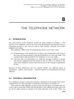
processing due to the greater complexity of the system. Figure 7.l shows a block
diagram of a typical television receiver.
The antenna picks up the electromagnetic radiation from the transmitter and feeds
it to the radio-frequency amplifier. After amplification and filtering to attenuate other
incoming signals from other transmitters, the signal goes to the mixer where it is
mixed with the output from the local oscillator. As before, the local oscillator and the
radio-frequency amplifier are tuned to track each other with a constant frequency
difference equal to the intermediate frequency. The intermediate frequency for the
television receiver is usually 45.75 MHz. The signal is subjected to further filtering
before it proceeds to the video demodulator for the recovery of the baseband
information in the signal. The next stage is to separate the composite video signal
into its three components, namely the video proper, the FM sound subcarrier and its
sidebands, and the vertical and horizontal control pulses. The video signal is
amplified to the level required to drive the picture tube by the video amplifier and
the vertical and horizontal control pulses are suitably conditioned and used in the
deflection systems of the receiver to synchronize it to the transmitter – a condition
that must be met for proper reproduction of the images sent. The FM signal is
amplified, amplitude limited and detected and after some amplification it is used to
drive the loudspeaker.
187
Telecommunication Circuit Design, Second Edition. Patrick D. van der Puije
Copyright # 2002 John Wiley & Sons, Inc.
ISBNs: 0-471-41542-1 (Hardback); 0-471-22153-8 (Electronic)
Figure 7.1. The block diagram of the television receiver.
188
7.2 COMPONENT DESIGN
7.2.1 Antenna
Antenna design is outside the scope of this book. However, a brief qualitative
discussion can be found in Section 2.9. Further discussion of antennas for
commercial FM reception is presented in Section 5.2.1. Frequencies for commercial
FM (88–108 MHz) occupy the spectrum between channels 6 and 7 of the VHF
television frequencies (54–88 MHz and 174–216 MHz, respectively). Except for
slight differences in the physical dimensions, the antennas tend to take the same
form. These are frequency ranges in which a half-wavelength dipole antenna has
reasonable physical dimensions (0.7–2.7 m).
7.2.2 Superheterodyne Section
The radio-frequency amplifier is tunable over the VHF frequency range. This is
accomplished with a variable capacitor which is mechanically ganged to the variable
capacitor which tunes the local oscillator. The objective is to generate a local
oscillator frequency which is equal to the radio-frequency amplifier center frequency
plus the intermediate frequency. In this case the range of the radio frequency is from
approximately 57 MHz (channel 2) to approximately 85 MHz (channel 6) and from
approximately 177 MHz (channel 7) to approximately 213 MHz (channel 13) for
VHF television. The bandwidth is nominally 6 MHz and the radio-frequency gain is
between 20 and 50 times. Since the video intermediate frequency is normally
45.75 MHz, the local oscillator has to be tunable from 102.75 to 258.75 MHz. From
Figure 6.21, it can be seen that there are two carrier frequencies in the composite
video signal: the video carrier and the voice carrier. The voice carrier is 4.5 MHz
above the video carrier, after mixing the video intermediate frequency is at
45.75 MHz and the voice intermediate frequency is at (45.75 À 4.50) or
41.25 MHz. In general parlance, the radio-frequency amplifier, the local oscillator
and the mixer are called the television front end or simply television tuner. These
components are generally housed in a separate shielded container in an attempt to
control the effects of stray electromagnetic fields and stray capacitive and inductive
elements. The principles to be followed in the design of the circuits in the television
front end are the same as discussed earlier in connection with radio. The only things
that have changed are the frequency of operation and the bandwidth requirements.
Greater attention must be paid to the physical layout of the practical circuits. Radio-
frequency amplifiers were discussed in Section 2.8. Oscillator design can be found in
Section 2.4 and mixer design in Section 3.4.3.
7.2.3 Intermediate-Frequency Amplifier
Like all superheterodyne receiver systems, the detailed selection of the desirable and
the rejection of the undesirable frequencies take place at the intermediate-frequency
stage. At the same time, some parts of the spectrum may be emphasized to equalize
7.2 COMPONENT DESIGN 189
the quality of the low-frequency video (large uniform areas) and the high-frequency
video (areas with fine details). The exact frequency response of the video inter-
mediate-frequency amplifier is of no importance at this point except to point out that
it is designed to compensate for the frequency response of the vestigial sideband
filter in the transmitter. To understand the techniques used to achieve this objective
requires a good understanding of the theory of filter design which is beyond the
scope of this book. A list of books on filter design is provided in the bibliography at
the end of Chapter 3.
The output of the intermediate-frequency amplifier must be of the order of several
volts to drive the video detector that follows. Intermediate-frequency amplifiers were
discussed in Section 3.4.4.
7.2.4 Video Detector
It will be recalled that the video signal is amplitude modulated and, in theory, it
requires a simple envelope detector to demodulate it. However, the situation is
complicated somewhat by the fact that the input signal to the detector is a vestigial
sideband signal.
7.2.4.1 Demodulation of Vestigial Sideband Signals. When a carrier of
frequency o
c
is amplitude modulated by a signal of frequency o
m
, the result is
f
1
ðtÞ¼A½1 þ m cos o
m
t cos o
c
t ð7:2:1Þ
f
1
ðtÞ¼A cos o
c
t þ
mA
2
½cosðo
c
þ o
m
Þt þ cosðo
c
À o
m
Þt: ð7:2:2Þ
In vestigial sideband modulation, one of the sidebands is removed; it could be either
of them but in this case it is assumed that it is the lower sideband. Also complete
removal is assumed. For simplicity, we have
f
2
ðtÞ¼A cos o
c
t þ
mA
2
cosðo
c
þ o
m
Þt ð7:2:3Þ
f
2
ðtÞ¼A cos o
c
t þ
mA
2
cos o
c
t cos o
m
t À
mA
2
sin o
c
t sin o
m
t ð7:2:4Þ
f
2
ðtÞ¼Að1 þ
m
2
cos o
m
tÞ cos o
c
t À
mA
2
sin o
c
t sin o
m
t: ð7:2:5Þ
The amplitude of the carrier signal is
jf
2
ðtÞj ¼
ffiffiffiffiffiffiffiffiffiffiffiffiffiffiffiffiffiffiffiffiffiffiffiffiffiffiffiffiffiffiffiffiffiffiffiffiffiffiffiffiffiffiffiffiffiffiffiffiffiffiffiffiffiffiffiffiffiffiffiffiffiffiffiffiffiffiffiffiffiffiffiffiffi
A
2
1 þ
m
2
cos o
m
t
2
þ
mA
2
sin o
m
t
2
s
ð7:2:6Þ
jf
2
ðtÞj ¼
ffiffiffiffiffiffiffiffiffiffiffiffiffiffiffiffiffiffiffiffiffiffiffiffiffiffiffiffiffiffiffiffiffiffiffiffiffiffiffiffiffiffiffiffiffiffiffiffiffiffiffiffiffiffiffi
A
2
1 þ
m
2
4
þ A
2
m cos o
m
t
s
: ð7:3:7Þ
190 THE TELEVISION RECEIVER
When the depth of the modulation is low, m < 1 and m
2
=4 ( 1,
jf
2
ðtÞj % Að1 À m cos o
m
tÞ
1=2
: ð7:2:8Þ
Using the binomial expansion, we get
jf
2
ðtÞj % A 1 þ
m
2
cos o
m
t
: ð7:2:9Þ
This contains the modulating frequency o
m
as well as its higher harmonics whose
amplitudes diminish very rapidly.
The conclusion is that a vestigial sideband signal can be demodulated using a
simple envelope detector so long as the modulation index is much less than unity. It
is worth noting that the amplitude of the output signal is one-half of what it would
have been if both sidebands had been present. Envelope detectors were discussed in
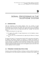
Section 3.2. An example is given in Section 3.4.6. Figure 7.2 shows the input and
output waveforms of a typical television envelope detector.
7.2.5 The Video Amplifier
The design of video amplifiers was discussed in Section 6.3.4. In the television
receiver, the load of the video amplifier is the grid of the cathode ray tube (usually
called the picture tube). This requires voltages between approximately 50 V and
100 V and, in theory, no current flows in the grid circuit. However, the grid represents
a capacitive load and a capacitance requires the movement of charge (current) to
change the voltage across it. The output stage of the video amplifier must be capable
of providing the necessary current and hence power. Another way of saying the same
thing is that the output stage of the video amplifier must have a low output resistance
so that the grid capacitance can be charged much faster than the fastest change in
voltage present in the video signal.
7.2.6 The Audio Channel
From the output of the video detector, a bandpass amplifier selects and boosts the
FM signal centered at 4.5 MHz. The limiter is described in Sections 4.3.3.1 and
4.3.3.2, and the FM detector is identical to that described in Section 4.3.3.4. The
audio-frequency amplifier was described in Section 2.7. The loudspeaker was
discussed in Section 3.4.8.
7.2.7 Electron Beam Control Subsystem
In the television transmitter, the pulse generator output was used to control the
vertical and horizontal sweeps of the electron beam which scanned the mosaic in the
camera tube. The same pulses were added to the video signal together with the
4.5 MHz FM voice carrier to make up the composite video. Figure 7.2 shows two
7.2 COMPONENT DESIGN 191
Figure 7.2. A typical intermediate-frequency television signal before and after detection.
192
such pulses (horizontal sync pulses only shown). The horizontal synchronization
pulses are used to control the initiation of the horizontal sweep of the electron beam
in the picture tube so that synchronism with the horizontal sweep of the electron
beam in the camera tube is maintained. Similarly, the vertical synchronization pulses
are used to keep the camera and picture tubes in step in the vertical direction. It is
very important to keep the camera and picture tubes in synchronism in both
directions, otherwise no meaningful image appears on the picture tube. The first
step is to channel the timing information in the sync pulses into a separate circuit for
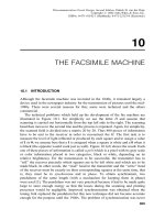
further processing. Figure 7.3 is a block diagram of the electron beam control
subsystem.
The composite video signal is fed into the sync-pulse separator which takes out
both vertical and horizontal sync pulses. The output is used to drive the two separate
branches of the system. The vertical branch has the vertical sync separator which is
designed to produce an output only when a vertical pulse is present at the input. The
two timing signals undergo essentially identical process steps, namely synchroniza-
tion to the oscillator, generation of the sweep signal, and amplification to obtain
enough power to drive the deflection coils. It is important to remember that the
vertical sync pulses have a frequency of 60 Hz whereas the horizontal runs at
15.75 kHz.
The sync pulses have the following timing characteristics:
Vertical Horizontal
Field period: 16.683 ms Line period: 63.556 ms
Blanking period: 1.335 ms Blanking period: 10.5–11.4 ms
Scan period: 15.348 ms Scan period: 52.156–53.056 ms
7.2.7.1 Sync Pulse Separator. The basic sync pulse separator is a simple
transistor invertor such as shown in Figure 7.4.
The ratio of R
1
to R
2
is chosen so that the transistor remains in cut off until the
applied voltage exceeds the blanking level (black level of the video signal). The
transistor then conducts and, with an appropriate value for R
3
, it goes into saturation.
The output of the circuit is then a series of rectangular pulses coincident with the
sync pulses, but inverted. These pulses are used directly to control the horizontal
deflection oscillator.
7.2.7.2 Vertical Sync Separator. It must be recalled that the horizontal sync
pulses are 5 ms long while the vertical are 190 ms. They are easily separated by using
a simple low-pass RC filter with a suitable time constant. Figure 7.5 shows a typical
vertical sync separator circuit.
The RC low-pass filter shown in Figure 7.5 has three sections which should give
it a higher rate of amplitude change with frequency. The difference between the two
frequencies to be filtered (60 Hz and 15.75 kHz) make the filter design simple.
7.2 COMPONENT DESIGN 193
Figure 7.3. The block diagram of the electron beam scan control system.
194
7.2.7.3 Vertical Deflection Oscillator. The vertical deflection oscillator is an
astable multivibrator which is synchronized to the vertical sync pulses. Figure 7.6(a)
shows the circuit diagram of the astable multivibrator.
When the dc power is first switched on, current is supplied to the bases of both
transistors and they will both tend to conduct. In general, it can be assumed that one
of the two transistors (say Q
1
) will conduct a little bit better than the other. The
voltage at the collector of Q
1
will therefore drop a little faster than that of Q
2
.
Because it is not possible to change the voltage across the capacitor C
2
instantaneously, the voltage at the base of Q
2
will be forced downwards. This will
have the effect of reducing the forward bias on the base-emitter junction of Q
2
. The
Figure 7.4. The circuit used for separating the horizontal sync pulse. The threshold is set by
the relative values of R
1
and R
2
.
Figure 7.5. The vertical sync pulse separator. The low-pass filter ensures that it does not react
to the horizontal sync pulse.
7.2 COMPONENT DESIGN 195
Figure 7.6. (a) The circuit diagram of the astable multivibrator. (b) The voltage waveforms for
the bases and collectors.
196 THE TELEVISION RECEIVER
collector current of Q
2
will be reduced and this will make the collector voltage of Q
2
go up. Again the voltage across C
1
cannot change instantly so the collector voltage
of Q
2
will tend to force the base of Q
1
upwards. This will cause the base-emitter
junction of Q
1
to become more forward biased than it was. More collector current
will flow and the collector voltage of Q
1
will drop even more. We are now back to
where we started and the downward change which started the chain of events is now
magnified. This is evidently a regenerative (positive feedback) process which ends
with Q
1
in full conduction and Q
2
cut-off. With the appropriate choice of R
c1
and
R
b1
, Q
1
goes into saturation, essentially its collector voltage is zero. This phase of
the operation is called the regenerative phase and, because regenerative phenomena
are basically unstable, they tend to happen very fast.
The next phase of the operation, called the relaxation phase, starts as C
2
begins to
charge up through R
b2
. The voltage at the node B
2
will start to rise exponentially, and
eventually it will reach a value sufficient to bias the base-emitter junction of Q
2
in
the forward direction. A new regenerative phase starts. Q
2
starts to conduct and its
collector voltage starts to drop. The voltage drop will be passed by C
1
to the base of
Q
1
which will now conduct less, its collector will come out of saturation (that is, go
positive) and will be passed by C
2
to the base of Q
2
. Q
2
will conduct more heavily
and its collector voltage will drop even faster than before. Again the change that set
the chain of events in motion has been magnified by the gain of the transistors. Q
2
will eventually go into full conduction (saturation) and Q
1
will be cut off. The
appropriate choice of the values of R
b2
and R
c2
will ensure that Q
2
goes into
saturation driving the base of Q
1
to a negative value equal to the dc supply voltage.
C
1
starts to charge up exponentially headed for the positive dc supply voltage, but
when it gets to the value required to forward bias the base-emitter junction of Q
1
, Q
1
will start to conduct again and the next regenerative phase is repeated followed by
the next relaxation phase ad infinitum.
The voltage waveforms at the collector and bases are shown in Figure 7.6(b).
A simple way to synchronize the astable multivibrator to the vertical sync pulse is
to couple the leading edge of the sync pulse to the base of one of the two transistors
using a differentiator circuit to get a sharp clock pulse. In order to get a stable
synchronization, the astable multivibrator should operate at a frequency slightly
lower than the vertical sync pulse frequency when free-running. The design
principles discussed above are best illustrated by an example.
Example 7.2.1 Vertical Deflection Oscillator Design. Design an astable multi-
vibrator with a mark-to-space ratio equal to 15.35=1.34 (see scan and blanking
periods in Section 7.2.7) and synchronize it to the leading edge of a 60 Hz square
wave derived from the vertical sync pulse of a television receiver. The following are
given:
(1) supply voltage, 12 V dc,
(2) two NPN silicon transistors, b ¼ 100 and V
be
¼ 0:7V,
(3) load current ¼ 10 mA.
7.2 COMPONENT DESIGN 197
Solution. Assuming that:
(a) the collector loads of the transistors are the loads of the oscillator,
(b) the collector voltage is zero when the transistor is in saturation,
the collector resistors are
R
c1
¼ R
c2
¼
12
10 mA
¼ 1:2kO: ð7:2:10Þ
The time-constant must be chosen so that one complete cycle takes slightly longer
then 1=60 s, for example 17.0 ms. This means that one transistor will be in
conduction for 15.6 ms and the other for 1.36 ms.
From Figure 7.6(b), it can be seen that the equation of the voltage on the base of
Q
1
is
v
b1
¼ 2V ð1 À e
Àt= t
ÞÀV : ð7:2:11Þ
The time taken by the base voltage of Q
1
to reach 0.7 V is t ¼ 15: 6 ms. The time-
constant is
t ¼ 20:71 ms: ð7:2:12Þ
Because the transistor has a b ¼ 100, the base current required to cause saturation in
each transistor is 10 mA=100 ¼ 100 mA. The base resistor is
R
b1
¼ R
b2
¼
ð12 À 0:7Þ
100 mA
¼ 113 kO: ð7:2:13Þ
The time-constant t
1
¼ C
1
R
b1
; therefore,
C
1
¼ 0:183 mF: ð7:2:14Þ
Similarly, t
2
¼ 1:79 ms ¼ C
2
R
b2
, where
C
2
¼ 0:016 mF: ð7:2:15Þ
To produce the clock pulse coincident with the leading edge of the square wave, the
differentiation circuit shown in Figure 7.7 is used. The condition for approximate
differentiation is that the time-constant CR ( T , the period of the input voltage. The
diode clips off the unwanted negative-going spike.
The base voltage of Q
1
is now an exponential curve with the positive clock pulse
superimposed on it as shown in Figure 7.8. It is clear from the diagram that, when
the clock pulse occurs at the time represented by the position a, the oscillator will
not synchronize to the clock pulse. However, when the clock pulse occurs in the
198 THE TELEVISION RECEIVER
position b the voltage at the base of Q
1
will exceed 0.7 V, Q
1
will go into the
regenerative mode and the oscillator will be synchronized.
7.2.7.4 Vertical Sweep Current Generator. A very simple sweep current
generator with a fairly linear output current with respect to time is shown in Figure
7.9. The circuit also act as a class-A amplifier and drives the yoke coil of the vertical
deflection system.
Figure 7.7. The differentiation circuit with its input and output waveforms.
Figure 7.8. The base voltage of the transistor used in the astable multivibrator showing the
synchronizing pulses.
7.2 COMPONENT DESIGN 199
The transistor is biased for class-A operation. The collector is connected to the dc
power supply by a large inductance with negligible resistance, that is, it is an open-
circuit at the frequency of operation but a short-circuit to direct current. When the
square wave from the multivibrator is applied to the base of the transistor, the
collector current of the transistor will be a square wave. During current transitions a
voltage will be developed across L
c
; otherwise; the yoke inductor L
y
has the dc
power supply connected directly across it. Because the dc voltage is a constant, di=dt
in L
y
is a constant. The capacitor C serves as a block to dc flowing to ground.
Because of the low frequency of operation, this circuit does not consume much
power, neither is there a large reactive power circulating in the circuit.
7.2.7.5 Horizontal Deflection System. From Figure 7.3, it can be seen that
the horizontal deflection system has the same modules as the vertical. The
description of the modules and their design will not be repeated. In practice, the
vertical and horizontal deflection systems are different and the differences arise
from:
(1) The vertical system operates at 60 Hz while the horizontal runs at 15.75 kHz,
(2) Deflection in the horizontal and vertical directions are in the ratio 4 : 3 (aspect
ratio),
(3) The horizontal deflection system is very sensitive to phase modulation and
hence the horizontal oscillator has to have an automatic phase control loop to
keep phase modulation as low as possible,
(4) High power ($ 50 W) is required to run the horizontal deflection coil if the
energy stored in it is dissipated at the end of each cycle. By using extra
circuitry, it is possible to return most of the energy to the dc source by
Figure 7.9. The circuit diagram of the driver for the vertical deflection yoke.
200 THE TELEVISION RECEIVER
resonating the inductance of the yoke with a suitable capacitor to cause
ringing at approximately 60 kHz,
(5) The high dc voltage ($10,000 V) required to run the picture tube can be
obtained by using a transformer coupling (auto-transformer) to step up the
voltage followed by a rectifier (tube type). A simplified circuit diagram of the
final stage of the horizontal deflection system is shown in Figure 7.10.
The horizontal oscillator is synchronized to the output of the sync separator. The
oscillator then drives the base of Q
2
with a string of rectangular pulses at
approximately 15.75 kHz. When Q
2
is on, it draws current through the primary of
the transformer T
1
. This causes a current to flow in the secondary, biassing Q
1
on
and putting it into saturation. The dc supply voltage V is therefore connected directly
across the primary terminal P of the auto-transformer and ground. Q
1
and the
winding of the autotransformer between node P and ground form an emitter
follower. The horizontal deflection yoke inductance, L
x
, which is connected to the
auto-transformer at node N , has a constant voltage, higher than V , connected across
it. The current that flows in L
x
is the linear ramp required to produce a linear
horizontal deflection. The capacitor C
c
blocks dc from flowing in L
x
, and it is a
short-circuit at the frequency of operation. At the end of the linear ramp, Q
2
is cut
off, a voltage is induced in the secondary of T
1
, and this is in the appropriate
direction to shut off Q
1
abruptly. Normally, the sudden termination of the current
flow in the auto-transformer and L
x
will generate a huge voltage spike in the attempt
to dissipate the energy stored in the inductances. However, the diode D
1
conducts
Figure 7.10. The driver of the horizontal deflection yoke with the extra-high voltage (EHV)
generator required for the anode of the picture tube.
7.2 COMPONENT DESIGN 201
providing a path for the current to flow into the tuned circuit made up of L
x
and C
r
.
L
x
and C
r
resonate (‘‘ ring’’) at approximately 60 kHz (four times the horizontal
deflection frequency). If the timing is set up correctly, the energy stored in the
resonant circuit will be flowing from the capacitor into the yoke just as the next
current ramp is starting. This arrangement substantially reduces the amount of power
taken from the dc supply to drive the yoke. As no diode is connected across the
M
N portion of the auto-transformer, a large voltage spike appears across it. This is
rectified and used to bias the anode of the picture tube.
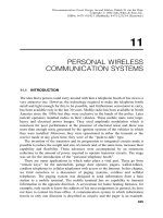
7.2.8 Picture Tube
The picture tube is an example of a cathode ray tube (CRT) used in a wide variety of
display systems. It consists of a glass cylinder which flares into a cone with a nearly
flat base. Figure 7.11 shows a cross-section of the typical CRT used for the display of
television images.
At the end of the glass cylinder, there is an electron gun. The electron gun is
made up of a cylinder, closed at one end and coated with oxides of barium and
strontium which give off electrons when heated. The CRT has control grid(s),
focussing and deflection electrodes or coils. An electric current is passed through the
heater coil to bring the temperature of the cathode to the appropriate value, electrons
are given off and, under the influence of a positive voltage placed on the anode, the
electrons travel down the tube and strike the screen at high velocity. The grid(s)
carry a negative voltage which can be varied to control the number of electrons that
can leave the cathode and eventually reach the screen. The grid(s) therefore control
the intensity of the light forming the image. The electron lens is either an
electrostatic or a magnetostatic means of focusing the electrons, usually to produce
a small spot on the screen.
Figure 7.11. A cross-sectional view of the cathode ray tube (CRT). Reprinted with permission
from T. Soller, M. A. Starr and G. E. Valley, Cathode Ray Tube Displays, Boston Tech. Pub.
Lexington, MA, 1964.
202 THE TELEVISION RECEIVER
The rest of the tube is made up of the deflection electrodes or coils which cause
the electron beam to move on the screen on the application of the appropriate voltage
or current. The anode is a conductive thin film on the inside wall of the flare as
shown and requires several thousand volts positive for proper operation. The screen
is coating with silicates, sulfides, fluorides and alkali halides which emit light when
bombarded by electrons. The color of the light emitted is determined by the
characteristic wavelength associated with each chemical element present in the
screen material. For example, copper-activated 85% zinc sulfide and 15% cadmium
sulfide gives off yellow light while 93% zinc sulfide and 7% cadmium sulfide
produces a blue-green phosphor. The persistence (or afterglow) of the phosphor can
be varied to suit different conditions.
Most modern CRTs used in television receivers have an electrostatic focussing
system because it is simpler and less expensive to manufacture. The deflection
system is, however, magnetostatic because of the tendency to have shorter tubes and
larger screen areas.
7.3 COLOR TELEVISION RECEIVER
7.3.1 Demodulation and Matrixing
In Section 6.3.8, it was established that black-and-white and color television signals
had many common features. Their basic differences are:
(1) in addition to the luminance information (L
w
), the chrominance information
(L
r
À L
w
) and (L
b
À L
w
) is transmitted using a quadrature modulation (DSB-
SC) scheme with a (color) subcarrier of frequency approximately 3.58 MHz,
(2) on the back porch of the horizontal blanking pulse, an eight-cycle bursts of
the color subcarrier is superimposed.
One scheme used for the recovery of the original red, blue, and green signals is
shown in Figure 7.12. It is described as pre-picture tube matrixing.
From the output of the video detector, the color burst separator picks up the eight
cycles of the 3.58 MHz subcarrier and passes them onto the color subcarrier
regenerator. The regeneration circuit is essentially a very high Q-factor circuit
tuned to 3.58 MHz. The eight-cycle burst of signal causes the high Q circuit to go
into a free-running oscillation mode. The subcarrier must have limited variation in
both amplitude and phase, for proper synchronous detection, and therefore the decay
of the amplitude during the free-running period must be controlled. To maintain the
amplitude variation to 90% of the initial value for the time required to sweep one
horizontal line (63 ms) a Q-factor of 7000 is required. Crystals are used in the
regenerator because only crystals have the necessary high Q-factor.
The regenerated 3.58 MHz signal is split into two branches. The first branch goes
through a 90
phase shifter to produce the quadrature signal required for the
synchronous demodulation of the ðL
r
À L
w
Þ and ðL
b
À L
w
Þ signals contained in
the output of the color bandwidth filter. After demodulation, the matrix reproduces
7.3 COLOR TELEVISION RECEIVER 203
Figure 7.12. The schematic diagram for color separating in the receiver. This is described as pre-
picture tube matrix because the colors are separated outside the tube.
204
the third difference signal, namely (L
g
À L
w
). The composite video signal containing
the luminance information L
w
is now combined in the adders to give the original red,
green, and blue information. After suitable amplification, they drive the picture tube
cathodes. A variation on this scheme, called picture tube matrixing, produces the
(L
g
À L
w
) signal and the addition of the L
w
is carried out in the picture tube by
driving the grids and the cathodes differentially. This is shown in Figure 7.13.
When the I and Q signal scheme is used in the transmission, it must be decoded
into (L
r
À L
w
) and (L
b
À L
w
) after the synchronous detectors and before the signal is
applied to the matrix.
7.3.2 Component Circuit Design
The 90
phase shift circuit was discussed in Sections 4.4.3.1 and 4.4.3.2. The
synchronous detector (four-quadrant multiplier) was discussed in Sections 2.6.4 and
4.4.3.3. The design of the adder was described in Section 4.4.3.5. Video amplifier
design was discussed in Section 6.3.4.2.
7.3.2.1 Color Burst Separator. The eight cycles of the color burst subcarrier
riding on the back of the horizontal blanking pulse are shown in Figure 6.24. Since
this signal is required for the synchronous detection of the chrominance signal, no
part of the video signal must be allowed to get through the separator. The most
popular technique is to use the falling edge of the horizontal sync pulse to trigger a
gate open and to close the gate immediately after the time it takes the eight cycles of
3.58 MHz to come through (2.23 ms). The circuit used is shown in Figure 7.14.
Q
2
is an amplifier biased in the off state by the resistors R
3
; R
4
; R
5
, and R
6
. Its
emitter is coupled through the tuned circuit LC to the collector of Q
1
. The base of Q
1
is driven by the output from the horizontal oscillator (see Figure 7.3). The resonant
frequency of the LC circuit is adjusted so that the rise-time of the rectangular
waveform from Q
1
is delayed long enough to let only the eight cycles of the
3.58 MHz signal through to the collector of Q
2
.
7.3.2.2 Color Subcarrier Regenerator. A typical circuit of the color sub-
carrier regenerator is shown in Figure 7.15.
The output from the transistor Q
1
is taken from both the collector and the emitter.
C
2
is adjusted to cancel the shunt capacitance of the crystal (see Figure 2.18). The
crystal is chosen so that its series resonant frequency is 3.58 MHz and it resonates
when it is excited by the subcarrier. In the series mode resonance, the crystal
impedance is essentially a short-circuit (ideal voltage source). The losses in R
e
and
R
3
in parallel with R
4
are therefore insignificant. The circuit has a high enough Q-
factor to perform about 217 cycles of free-running oscillations between bursts of
color subcarrier signals. Q
2
is used as a buffer amplifier. In some earlier models, the
signal from the regenerator was used to synchronize an LC oscillator whose output
was then used for the demodulation. This is an expensive way to solve the problem
in view of the satisfactory performance of the free-running system.
7.3 COLOR TELEVISION RECEIVER 205
Figure 7.13. The block diagram for color separation in the tube. Note that the color differences are
applied to the tube directly.
206
7.3.2.3 The Matrix. The function of the matrix is to reproduce the third
difference signal (L
g
À L
w
). Equation (6.4.4) was derived for this operation and it
is repeated here.
ðL
g
À L
w
޼0:30
0:59
ðL
r
À L
w
ÞÀ
0:11
0:59
ðL
b
À L
w
Þ: ð7:3:1Þ
It is clear that this can be achieved with a simple resistive network and a phase
reversing buffer amplifier.
7.3.3 Color Picture Tube
In Section 7.2.8, it was stated that different phosphor materials coatings on the
screen of the picture tube give different colors of light when bombarded by electrons.
A number of different techniques for producing images in color on the CRT exist; all
of them rely on this phenomenon. The most successful of these uses the shadow
mask technique. Figure 7.16 illustrates the basic concept.
Three electron guns representing the three primary colors are mounted symmet-
rically on a plane perpendicular to the axis of the tube. Electrons from each gun will
therefore bombard different areas of the screen after going through the holes in the
shadow mask. If the area of the screen corresponding to the blue gun is coated with a
phosphor that produces blue light and so on, then it is clear that, by depositing the
different phosphors materials in dots grouped in threes at the appropriate points on
the screen, the different colors can be reproduced by modulating the relative
saturation of each component.
The shadow mask technique has the following disadvantages:
Figure 7.14. The color subcarrier burst separator. The output is used to synchronize the color
subcarrier regenerator.
7.3 COLOR TELEVISION RECEIVER 207
Figure 7.15. The color subcarrier regenerator. Note that, because of the high Q factor of the crystal in
the circuit, it is virtually free-running between bursts of the subcarrier.
208
(1) The shadow mask has to be very carefully aligned for good color
resolution.
(2) The presence of the mask reduces the average brightness (luminance) of the
image but this can be compensated for by increasing the electron emission of
the guns.
7.4 HIGH-DEFINITION TELEVISION (HDTV)
High-definition television is an attempt to produce images of quality comparable to
that of a 35 mm motion picture film. The proposed system has 1125 lines of scan
with 60 fields per second. Japanese HDTV uses analog techniques and requires a
bandwidth of 20–25 MHz. In North America, HDTV uses digital technology which
permits the compression of the data to fit into a 6 MHz bandwidth. The standard for
digital television has the acronym MPEG-2 and it can achieve a bit compression
ratio of 55 : 1. It does this by retaining most of the data and presenting only changes
in a picture frame. Despite the improvement in picture definition achieved by HDTV
the viewing public has been slow to switch over to the new format. The high price
tag for the HDTV receiver means that only a very select number of viewers are
willing to adopt the new system. Equally, the broadcasting organizations are
unwilling to invest large amounts of money in HDTV to re-equip their studios
Figure 7.16. The color picture tube showing details of the shadow mask. Reprinted with
permission from H. B. Law, ‘‘Shadow Mask’’, Proc. IRE (now IEEE), 39(10), 1951.
7.4 HIGH-DEFINITION TELEVISION (HDTV) 209
when they are not sure of reasonable returns on their investment. Table 7.1 compares
the current standard (NTSC) to HDTV.
BIBLIOGRAPHY
1. Kennedy, G., Electronic Communication Systems, McGraw-Hill, New York, 1970.
2. Smith, J., Modern Communication Circuits, McGraw-Hill, New York, 1986.
3. Parker, N. W., ‘‘ Television Image-Reproducing Equipment’’,inElectronics Engineers’
Handbook, Fink, D. G. and Christiansen, D. (Eds), 2nd Ed., McGraw-Hill, New York,
1982.
4. Sherr, S., Fundamentals of Display System Design, Wiley-Interscience, New York, 1970.
5. Soller, T., Starr, M. A. and Valley, G. E., Cathode Ray Tube Displays, Boston Tech.
Publishers, Inc., Lexington, MA, 1964.
6. Law, H.B., ‘‘ Shadow Mask’’ , Proc. IRE, 39(10), 1187, 1951.
PROBLEMS
7.1 Give two advantages of vestigial sideband modulation systems. What are their
disadvantages? A transmission consists of a carrier and its upper sideband.
Show that, when the modulation index is small compared to unity, an ordinary
envelope detector can be used to demodulate it. Calculate the signal power in a
vestigial sideband signal if the peak value of the carrier voltage is 5 V when the
load resistor is 2:5kO and the modulation index is 0.15. You may assume that
the diode is ideal.
7.2 A television receiver is tuned to receive a transmission with a carrier frequency
67.25 MHz (Channel 4). If the intermediate frequency is 45.75 MHz, what is
the possible frequency(ies) at the local oscillator terminals of the mixer? If
there are two possible frequencies, does one of them offer an advantage over
the other? The local oscillator signal for the television receiver is generated at a
lower frequency and multiplied by a factor of 512. Calculate the frequency of
the oscillator and design a Hartley-type oscillator given that the tuning
TABLE 7.1
NTSC HDTV
Technology Analog Digital
Bandwidth 6 MHz 6 MHz
Total no. of lines 525 1125
Actual no. of lines 486 1080
Aspect ratio 4 Â 316Â 9
Max. resolution 720 Â 486 1920 Â 1080
Sound 2 channels (stereo) 5:1
2
channels
2
The 0.1 channel refers to a subwoofer for bass ‘‘sounds you can feel’’.
210 THE TELEVISION RECEIVER
capacitor has the value 144 pF. Discuss the precautions you would take to
minimize changes in the frequency of oscillation.
7.3 Using suitable block diagrams and derived equations, explain how quadrature
multiplex is used to transmit and receive the chrominance information in a
color TV system. State the conditions which must be satisfied for demultiplex-
ing to be possible. How are these conditions met in the domestic TV receiver?
7.4 Describe the construction and operation of a color TV picture tube. Explain
why a color tube requires a higher (EHV) dc voltage than the monochrome for
equal luminance.
7.5 Describe with the help of a suitable diagram the operation of a color subcarrier
regenerator.
Show that for a series-tuned RLC circuit at resonance:
(1) The total energy stored in the circuit is a constant,
(2)
Q
0
¼ 2p
Energy stored
Energy dissipated per cycle
: ðP7:5Þ
In a crystal-controlled color subcarrier regenerator operating at 3.58 MHz, the
total energy remaining in the circuit after 218 cycles of free-running oscillation
is 90% of its original value. Calculate the peak value of the voltage across the
capacitor at the end of the free-running cycle and estimate the Q
o
of the circuit.
7.6 What is a video signal? Explain why a video amplifier has to be used in
conjunction with a television camera tube.
A television system has the following features:
(1) 625 lines per frame with interlacing,
(2) 25 frames per second,
(3) 5% of the trace period is used for the retrace,
(4) the aspect ratio is 4 : 3.
Assuming equal resolution on the vertical and horizontal axes, calculate the
bandwidth required to handle the signal.
PROBLEMS 211